

- Operating InstructionsRobacta Drive CMT-PAP G
- Safety
- Installation and commissioning
- Device concept
- Original equipement and tools
- Recommended torch necks
- Change Wire Guide Insert
- Changing the torch neck
- Install Wear Parts on Drive Unit
- Fitting and connecting the hosepack
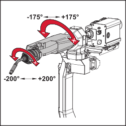
- Maximum axis rotation
- Connecting the wire buffer
- Connecting the welding torch
- Connecting the wirefeed hose
- Controls and functions
- Set Contact Pressure
- MTG 2500 - Replacing the components
- MTG 4000 - Replacing the components
- Care, maintenance and disposal
- Troubleshooting
- Technical data
012-13042026
Safety
WARNING!
Danger from incorrect operation and work that is not carried out properly.
This can result in serious personal injury and damage to property.
All the work and functions described in this document must only be carried out by technically trained and qualified personnel.
Read and understand this document in full.
Read and understand all safety rules and user documentation for this device and all system components.
WARNING!
Danger from machines that start up automatically.
This can result in serious personal injury and damage to property.
In addition to these operating instructions, the safety rules issued by the manufacturer of the robot and welding systems must also be observed.
For your personal safety, ensure that all protective measures have been taken and will remain in place for the duration of your stay within the working area of the robot.
WARNING!
Danger from electric current.
This can result in serious personal injury and damage to property.
Before starting work, switch off all the devices and components involved and disconnect them from the grid.
Secure all the devices and components involved to prevent unintentional restarting.
WARNING!
Danger from electric current due to defective system components and incorrect operation.
This can result in serious personal injury and damage to property.
All cables, leads and hosepacks must always be securely connected, undamaged and correctly insulated.
Only use adequately dimensioned cables, leads and hosepacks.
WARNING!
Danger due to emerging wire electrode.
This can result in serious personal injuries.
Hold the welding torch so that the tip of the welding torch points away from the face and body.
Wear suitable protective goggles.
Do not point the welding torch at people.
Ensure that the wire electrode does not touch any electrically conductive objects.
WARNING!
Danger due to hot system components and/or equipment.
Can result in serious burns or scalding.
Before starting work, allow all hot system components and/or equipment to cool to +25°C/+77°F (e.g., coolant, water-cooled system components, wirefeeder drive motor, etc.)
Wear suitable protective equipment (e.g., heat-resistant gloves, safety goggles, etc.) if cooling down is not possible.
WARNING!
Danger from contact with toxic welding fumes.
This can result in serious personal injuries.
Always extract welding fumes.
Ensure an adequate supply of fresh air. Ensure that there is a ventilation rate of at least 20 m³ (169070.1 US gi) per hour at all times.
If in doubt, a safety engineer should be commissioned to check the pollution level in the workplace.
CAUTION!
Danger of burns from hot surface.
Serious personal injuries may result.
When the ambient temperature in operation is at its maximum of 40°C, the surface temperature of the Robacta Drive CMTPAP G can rise as high as 90°C. This is a normal operating temperature and does not endanger the Robacta Drive CMT-PAP G.
WARNING!
Danger from incorrect operation and work that is not carried out properly.
This can result in serious personal injury and damage to property.
All the work and functions described in this document must only be carried out by technically trained and qualified personnel.
Read and understand this document in full.
Read and understand all safety rules and user documentation for this device and all system components.
WARNING!
Danger from machines that start up automatically.
This can result in serious personal injury and damage to property.
In addition to these operating instructions, the safety rules issued by the manufacturer of the robot and welding systems must also be observed.
For your personal safety, ensure that all protective measures have been taken and will remain in place for the duration of your stay within the working area of the robot.
WARNING!
Danger from electric current.
This can result in serious personal injury and damage to property.
Before starting work, switch off all the devices and components involved and disconnect them from the grid.
Secure all the devices and components involved to prevent unintentional restarting.
WARNING!
Danger from electric current due to defective system components and incorrect operation.
This can result in serious personal injury and damage to property.
All cables, leads and hosepacks must always be securely connected, undamaged and correctly insulated.
Only use adequately dimensioned cables, leads and hosepacks.
WARNING!
Danger due to emerging wire electrode.
This can result in serious personal injuries.
Hold the welding torch so that the tip of the welding torch points away from the face and body.
Wear suitable protective goggles.
Do not point the welding torch at people.
Ensure that the wire electrode does not touch any electrically conductive objects.
WARNING!
Danger due to hot system components and/or equipment.
Can result in serious burns or scalding.
Before starting work, allow all hot system components and/or equipment to cool to +25°C/+77°F (e.g., coolant, water-cooled system components, wirefeeder drive motor, etc.)
Wear suitable protective equipment (e.g., heat-resistant gloves, safety goggles, etc.) if cooling down is not possible.
WARNING!
Danger from contact with toxic welding fumes.
This can result in serious personal injuries.
Always extract welding fumes.
Ensure an adequate supply of fresh air. Ensure that there is a ventilation rate of at least 20 m³ (169070.1 US gi) per hour at all times.
If in doubt, a safety engineer should be commissioned to check the pollution level in the workplace.
CAUTION!
Danger of burns from hot surface.
Serious personal injuries may result.
When the ambient temperature in operation is at its maximum of 40°C, the surface temperature of the Robacta Drive CMTPAP G can rise as high as 90°C. This is a normal operating temperature and does not endanger the Robacta Drive CMT-PAP G.
Installation and commissioning
Device concept
The Robacta Drive CMT-PAP G robot welding torch consists of a torch neck, drive unit, CrashBox and hosepack.
In combination with the wire buffer on the hosepack, the integral wire drive motor can quickly reverse the welding wire. The external wirefeed means that all wirefeed components can be replaced quickly. Many different torch neck designs facilitate easy access to the weld.
- General light-gauge sheet applications
- Spatter-free MIG brazing of galvanized light-gauge sheets
- Joining steel to aluminium.
Device concept
The Robacta Drive CMT-PAP G robot welding torch consists of a torch neck, drive unit, CrashBox and hosepack.
In combination with the wire buffer on the hosepack, the integral wire drive motor can quickly reverse the welding wire. The external wirefeed means that all wirefeed components can be replaced quickly. Many different torch neck designs facilitate easy access to the weld.
- General light-gauge sheet applications
- Spatter-free MIG brazing of galvanized light-gauge sheets
- Joining steel to aluminium.
Original equipement and tools
- Original equipment aluminium
- Original equipment steel/CuSi
- Original equipment CrNi
a) Graphite combination liners with end piece | |
b) Graphite | |
c) Bronze | |
d) Steel |
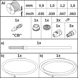
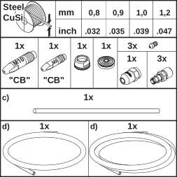
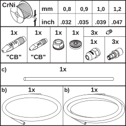
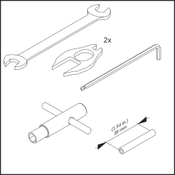
- Flat spanner, size 10/12
- Locking spanner, size 13
- Cutting pipe (for cutting the wire guide insert to length)
- Allen key, size 3
- Fitting wrench
Recommended torch necks
| (1) | Robacta MTG 2500 : 22°, 36° |
| (2) | Robacta MTG 4000 : 22°, 36° |
Contact tubes required:
M8 CB contact tube (with centre hole)
The following assembly steps are explained using a Robacta MTG 2500 as the example. Assembly with other torch necks is carried out in a similar manner.
1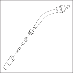
2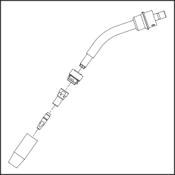
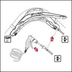
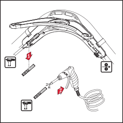
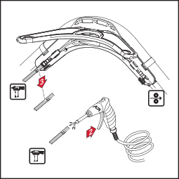
Change Wire Guide Insert
IMPORTANT! Ensure when cutting the wire guide insert to length that
- the contact tube is firmly installed in the torch neck
- the wire guide insert is pushed firmly onto the contact tube
- deburr the inside of the wire guide insert.
Use the power tong (item no. 42,0435,0009) to shorten the steel wire guide.
1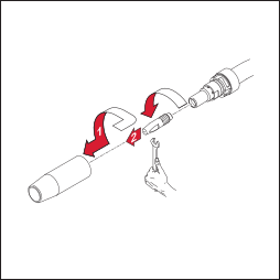
2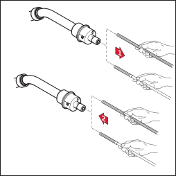
3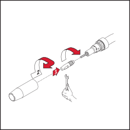
4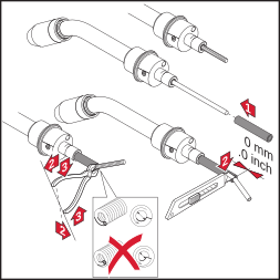
5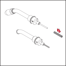
6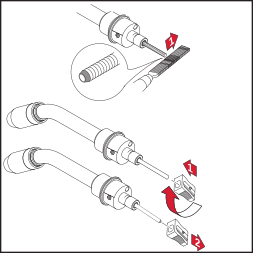
Changing the torch neck
WARNING!
Danger from extremely hot welding torch.
Can result in serious burns.
Changing, cleaning and inspection of components may only be carried out when torch body has cooled down.
CAUTION!
Danger from tightening the torch neck with excessive torque.
Destruction of coupling point can be the result.
Fasten the torch neck at the specified torque to prevent charring of the coupling point.
NOTE!
Before fitting the torch neck, ensure that the coupling point is not dirty.
* Do not turn it any further than it will go.
1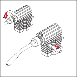
2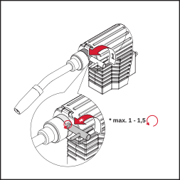
3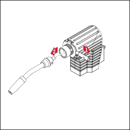
4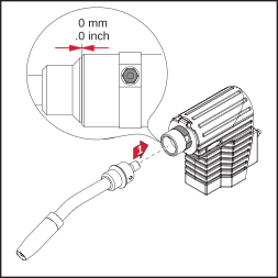
5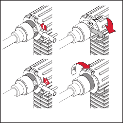
6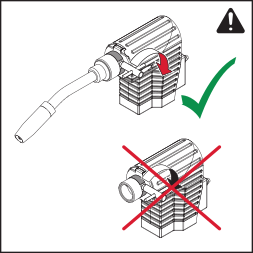
Install Wear Parts on Drive Unit
IMPORTANT! Take care to ensure the following when attaching the torch neck to the Robacta Drive CMT-PAP G coupling point:
- the wire guide insert must slide into the outlet section on the Robacta Drive CMT-PAP G coupling point without kinking.
- use only the locking tool supplied with the system to undo and tighten the drive rollers.
1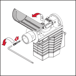
2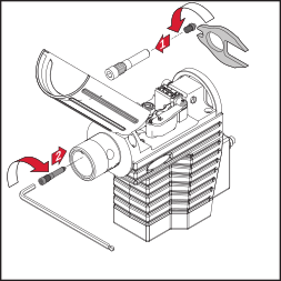
3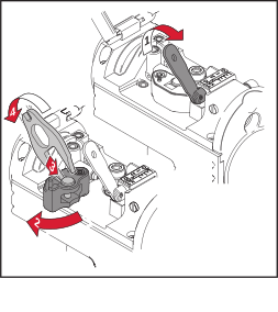
4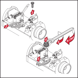
5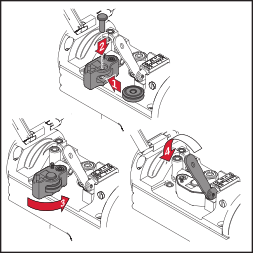
6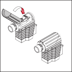
Fitting and connecting the hosepack
When fitting the hosepack, lay the connection cable in the recess (Fig. 3).
IMPORTANT! Be sure to connect the plug connectors correctly.
Torques:
* = 3.0 Nm
** = 3.0 Nm
1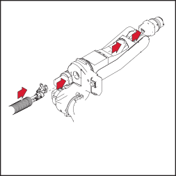
2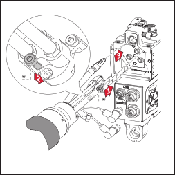
3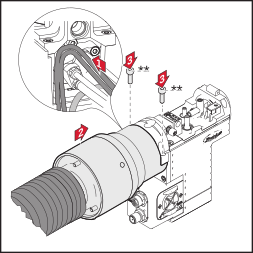
4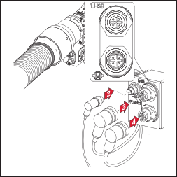
Maximum axis rotation
Connecting the wire buffer
IMPORTANT! Do not subject the wirefeeding hose between the wire buffer and the Robacta Drive CMT-PAP G to tensile stress.
1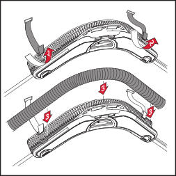
2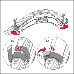
3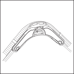
4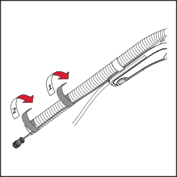
5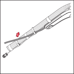
Connecting the welding torch
IMPORTANT! When connecting the torch check that
- all connections are firmly made
- all cables, pipes and hose packs are undamaged and correctly insulated.
* Control cable for wire buffer | |
** Torch blow-through option |
IMPORTANT! Ensure the blowthrough line is tightly sealed if the torch blow-through option is not being used.
1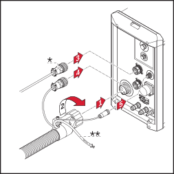
2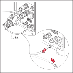
Connecting the wirefeed hose
CAUTION!
Risk of damage to dangling wirefeed hose.
This can result in severe damage to property.
Fasten the wirefeed hose to the hosepack in such a way that it cannot dangle close to surrounding machines or components (Fig. 3).
1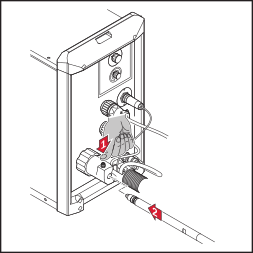
2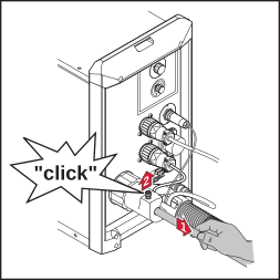
3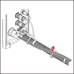
Controls and functions
WARNING!
Danger from welding wire emerging at speed.
This can result in serious personal injuries.
Hold the torch so that it points away from your face and body.
IMPORTANT! Deburr welding wire before feeding in. Open clamping lever when feeding in soft welding wire (AlSi 5, Al, and AlMg).
* LED illuminated | |
- green: ready for use - red: no control signal connection |
IMPORTANT! If LED is not illuminated: Check power supply to drive unit.
1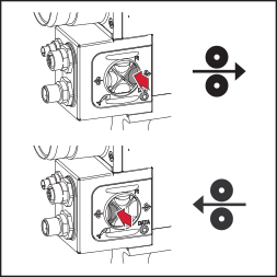
2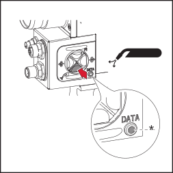
3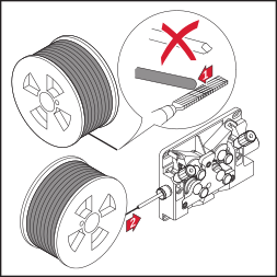
4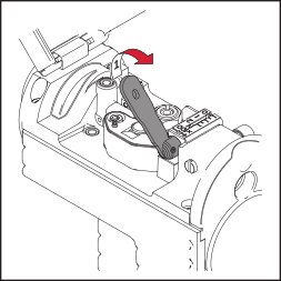
5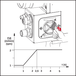
6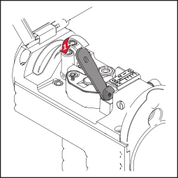
Set Contact Pressure
CAUTION!
Danger of injury due to rotating feed rolls.
This can result in serious personal injuries.
Do not touch the feed rolls.
IMPORTANT! The adjuster screw can only be adjusted when the welding wire has been fed in. The values stated are applicable when the adjuster screw is closed.
1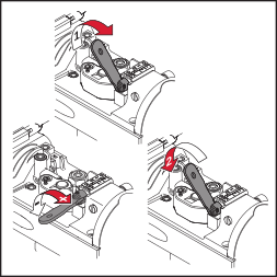
2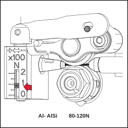
3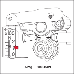
4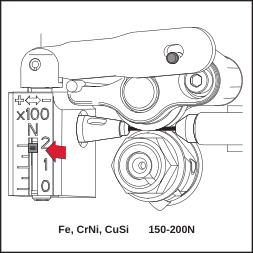
MTG 2500 - Replacing the components
CAUTION!
Danger of burning because of extremely hot torch.
This can result in serious personal injury.
For replacing of components as well as cleaning and checking of components make sure that the torch has cooled down.
* Key for bayonet (optional). This tool facilitates loosening and tightening of the gas jet locking mechanism.
1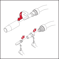
2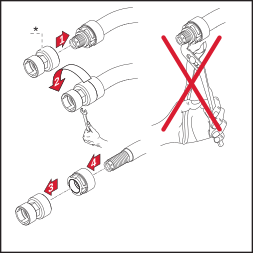
3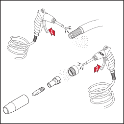
4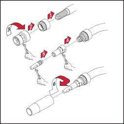
MTG 4000 - Replacing the components
CAUTION!
Danger of burning because of extremely hot torch.
This can result in serious personal injury.
For replacing of components as well as cleaning and checking of components make sure that the torch has cooled down.
1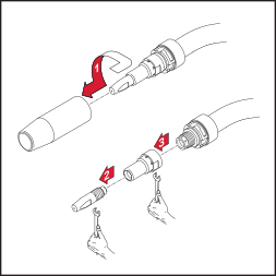
2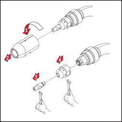
3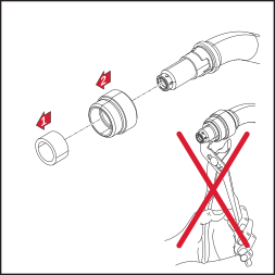
4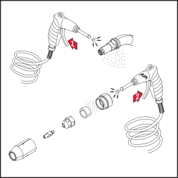
5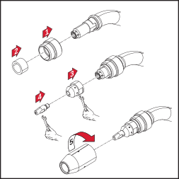
Care, maintenance and disposal
General
Regular and preventive maintenance of the CMT robot welding torch is essential for problem-free operation. The welding torch is subjected to high temperatures and heavy soiling. The welding torch therefore requires more frequent maintenance than other components in the welding system.
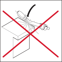
IMPORTANT! When removing welding spatter, avoid scoring or scratching the torch. Future welding spatter may become firmly lodged in score or scratch marks.
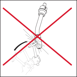
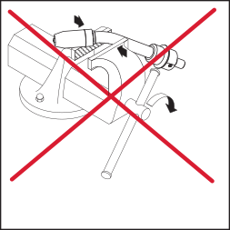
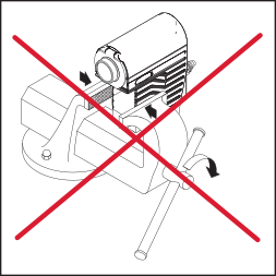
- Do NOT bend the torch neck
General
Regular and preventive maintenance of the CMT robot welding torch is essential for problem-free operation. The welding torch is subjected to high temperatures and heavy soiling. The welding torch therefore requires more frequent maintenance than other components in the welding system.
IMPORTANT! When removing welding spatter, avoid scoring or scratching the torch. Future welding spatter may become firmly lodged in score or scratch marks.
- Do NOT bend the torch neck
Every start-up
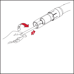
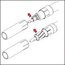
- Check the contact tube
- Replace worn out contact tube
- Remove welding spatter from gas nozzle (e.g. manually, by blowing off, or by using a Robacta Reamer or Robacta TC 1000)
- If there is dirt that cannot be removed from around the nozzle join, replace the gas nozzle
* Check spatter guard and insulation for damage |
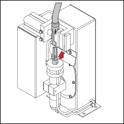
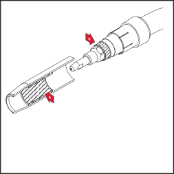
Every time the wirespool is changed
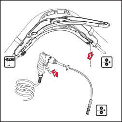
- Blow out inner liners with air at reduced pressure
- Recommended: Replace inner liner (at least once every 4 months)
- Check feed rollers and replace if required
- Clean the wirefeed hose and drive unit with reduced compressed air
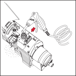
Disposal
Waste electrical and electronic equipment must be collected separately and recycled in an environmentally-friendly way, in accordance with the European Directive and national legislation. Used equipment must be returned to the distributor or disposed of via an approved local collection and disposal facility. Correct disposal of used equipment promotes the sustainable recycling of material resources. Failing to dispose of used equipment correctly can lead to adverse health and/or environmental impacts.
Packaging materials
Separate collection according to material. Check your local authority regulations. Crush containers to reduce size.
Liability
The Robacta Drive CMT-PAP G robot welding torch is designed for automated applications in conjunction with a collision box and at normal welding speeds.
Fronius International GmbH accepts no liability for any other use.
NOTE!
Undoing sealed screws can damage the drive unit. Fronius International GmbH accepts no liability if sealed screws are undone.
Troubleshooting
Troubleshooting
Troubleshooting
No welding current
Mains switch is on, indicators on the power source are lit, shielding gas available
| Cause: | Incorrect earth (ground) connection |
| Remedy: | Check the earth (ground) connection and clamp for correct polarity |
| Cause: | There is a break in the current cable in the Robacta Drive CMT-PAP G hosepack |
| Remedy: | Contact After-Sales Service |
| Cause: | Loose connection on hosepack |
| Remedy: | Check that hosepack is firmly in place |
Robacta Drive CMT-PAP G not working
Mains switch is on, indicators on the power source are lit
| Cause: | Control plug or motor plug not plugged in |
| Remedy: | Plug in the control plug or motor plug |
| Cause: | The control line or motor lead is defective |
| Remedy: | Contact After-Sales Service |
| Cause: | Drive unit is faulty |
| Remedy: | Contact After-Sales Service |
| Cause: | The interconnecting hosepack is faulty or not connected properly |
| Remedy: | Check the interconnecting hosepack and connection |
No shielding gas
All other functions are OK
| Cause: | The gas cylinder is empty |
| Remedy: | Change the gas cylinder |
| Cause: | Gas pressure regulator is faulty |
| Remedy: | Change the gas pressure regulator |
| Cause: | The gas hose is not connected, or is damaged or kinked |
| Remedy: | Fit gas hose, lay out straight or change |
| Cause: | Welding torch is faulty |
| Remedy: | Exchange the welding torch |
| Cause: | Gas solenoid valve in the CMT feeder is faulty |
| Remedy: | Exchange the gas solenoid valve in the CMT feeder |
Poor welding properties
| Cause: | Incorrect welding parameters |
| Remedy: | Check the settings |
| Cause: | Poor connection to earth (ground) |
| Remedy: | Ensure good contact to workpiece |
| Cause: | Not enough shielding gas, or none at all |
| Remedy: | Check the pressure regulator, gas hose, gas solenoid valve and torch gas connection. On gas-cooled welding torches, inspect the gas seals, use a suitable inner liner. |
| Cause: | Connections leaking |
| Remedy: | Tighten connections |
| Cause: | Contact tube does not fit or is damaged |
| Remedy: | Change the contact tube |
| Cause: | Wrong wire alloy or wrong wire diameter |
| Remedy: | Check the wirespool that has been inserted, check the weldability of the base metal |
| Cause: | The shielding gas is not suitable for this wire alloy |
| Remedy: | Use the correct shielding gas |
| Cause: | Unfavourable welding conditions: shielding gas is contaminated (by moisture, air), inadequate gas shielding (weld pool „boiling“, draughts), contaminants in the workpiece (rust, paint, grease) |
| Remedy: | Optimise the welding conditions |
| Cause: | Gas nozzle soiled |
| Remedy: | Remove welding spatter |
| Cause: | Turbulence caused by too high a rate of shielding gas flow |
| Remedy: | Reduce amount of shielding gas, recommended: shielding gas quantity (l/min) = wire diameter (mm) x 10 (e.g. 16 l/min for 1.6 mm welding wire) |
| Cause: | Too large a distance between the contact tube and the workpiece. |
| Remedy: | Reduce the distance between the contact tube and the workpiece (approx. 10-15 mm) |
| Cause: | Tilt angle of the welding torch is too great |
| Remedy: | Reduce the tilt angle of the welding torch |
| Cause: | The wirefeed components do not match the welding wire diameter |
| Remedy: | Use the correct wirefeed components |
| Cause: | Loss of gas or extraneous air |
| Remedy: | Check leak-tightness of blow-through line and blow-through valve. Check closure seal of blowthrough line (push-on nipple) |
Poor wirefeed
| Cause: | Wire does not fit |
| Remedy: | Check the position of the wire inlet nozzle relative to the feed rollers, and correct as necessary |
| Cause: | Brake force on the CMT wirefeeder set too high |
| Remedy: | Set the brake on the CMT wirefeeder to a looser setting |
| Cause: | Hole in contact tube constricted due to deposits |
| Remedy: | Change the contact tube |
| Cause: | The wire feed inner liner or wire feed insert is defective |
| Remedy: | Check the wire feed inner liner and wire feed insert for kinks, dirt, etc. ; change the faulty liner or wire feed insert |
| Cause: | The wirefeed rollers are not suitable for the wire electrode being used |
| Remedy: | Use suitable wire feed rollers |
| Cause: | The wirefeed rollers are exerting the wrong contact pressure |
| Remedy: | Check the contact pressure, adjust if necessary |
| Cause: | The wirefeed rollers are soiled or damaged |
| Remedy: | Clean the wirefeed rollers or exchange them for new ones |
| Cause: | Inner line was kinked while being inserted |
| Remedy: | When inserting the inner liner, only handle it around the infeed tube |
| Cause: | The inner liner has been cut too short |
| Remedy: | Replace the inner liner and cut it to the correct length |
| Cause: | Welding wire worn due to heavy contact pressure at the feed rollers |
| Remedy: | Reduce contact pressure at the feed rollers |
| Cause: | Welding wire contains impurities or is corroded |
| Remedy: | Use high-quality welding wire with no impurities |
| Cause: | Contact tube without centre hole is used |
| Remedy: | Change the contact tube, use contact tube with centre hole. |
The welding torch becomes very hot
| Cause: | The welding torch has been operated beyond its maximum duty cycle. |
| Remedy: | Lower the welding power or use a higher-capacity torch; observe the duty cycle and loading limits |
Contact tube only has a short service life
| Cause: | Welding wire worn due to heavy contact pressure at the feed rollers |
| Remedy: | Reduce contact pressure at the feed rollers |
| Cause: | Wrong dimension of contact tube |
| Remedy: | Use a contact tube of the correct dimension |
| Cause: | Duty cycle of welding torch has been exceeded |
| Remedy: | Shorten the ON times or use a higher-capacity torch |
| Cause: | Contact tube has overheated. No thermal dissipation, as the contact tube is fitted too loosely |
| Cause: | Tighten the contact tube |
NOTE!When using CrNi, the contact tube may be subject to a higher degree of wear due to the nature of the surface of CrNi welding wire. | |
Wirefeed buttons do not work
| Cause: | Plug-in connections of „control line/power source“ faulty |
| Remedy: | Check plug connection / Contact After-Sales Service |
| Cause: | Control line is faulty |
| Remedy: | Replace control line / Contact After-Sales Service |
Weld seam porosity
| Cause: | Soiled gas nozzle, causing inadequate gas-shielding of the weld seam |
| Remedy: | Remove welding spatter |
| Cause: | Either the shielding gas hose has holes in it, or the hose is not connected properly |
| Remedy: | Change the shielding gas hose, ensure the hose is connected properly |
| Cause: | The O-ring seals on the connection points are faulty |
| Remedy: | Change the O-ring seals |
| Cause: | Moisture/condensation in the shielding gas hose |
| Remedy: | Dry the shielding gas hose |
| Cause: | Shielding gas flow is either too high or too low |
| Remedy: | Correct the shielding gas flow |
| Cause: | Insufficient shielding-gas flow at the beginning or end of welding |
| Remedy: | Increase gas pre-flow or gas post-flow |
| Cause: | Rusty or poor quality welding wire |
| Remedy: | Use high-quality welding wire with no impurities |
| Cause: | Too much parting agent applied |
| Remedy: | Wipe off excess parting agent / apply less parting agent |
Technical data
CMT-PAP G
Explanation of symbols
 | Gas cooling |
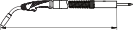 | Length of the hosepack |
X | Duty cycle in % |
ED* | Duty cycle |
Imax | max. welding current in A |
 | Electrode diameter |
Voltage measurement (V-Peak): 141 V
This product conforms to the requirements of IEC 60974-7.
| |
| MTG 2500 | MTG 3200 | MTG 4000 |
X / I max (10 min / 40°C) | [%] / [A] | - | - | - | |
X / I max (10 min / 40°C) | [%] / [A] | - | - | - | |
| [mm] | 0,8 - 1,2 | 0,8 - 1,2 | 0,8 - 1,6 |
| |
| Robacta Drive G | Robacta Drive CMT G / PAP | |
X / I max (10 min / 40°C) | [%] / [A] | - | - | ||
X / I max (10 min / 40°C) | [%] / [A] | - | - | ||
| [mm] | 0,8 - 1,6 | 0,8 - 1,2 (Alu 1,6) | ||
|
| [m] | 1,5 / 1,75 / 2,0 / 2,5 / 3,5 / | 4,25 / 6,25 / 8,25 | |
 | [V] DC | 42 | 55 | ||
 | [A] | 2,15 | 2,5 | ||
 | [min] | 0,5 - 22 | 0,5 - 22 | ||
| |
| Robacta G | Robacta G / CB PAP | |
X / I max (10 min / 40°C) | [%] / [A] | - | - | ||
X / I max (10 min / 40°C) | [%] / [A] | - | - | ||
| [mm] | 0,8 - 1,6 | 0,8 - 1,6 | ||
|
| [m] | 1,2 / 1,5 / 1,7 | 1,19 / 1,30 / 1,33 / 1,38 / 1,39 | |
| [V] DC | - | - | ||
| [A] | - | - | ||
| [min] | - | - | ||
| |
| MTB 330i G/R | MTB 400i G/R |
X / I max (10 min / 40°C) | [%] / [A] | 40 / ED* 330 | 40 / ED* 400 | |
X / I max (10 min / 40°C) | [%] / [A] | - | - | |
| [mm] | 0,8 - 1,6 | 0,8 - 1,6 |
| |
| MTB 330d G/R | MTB 400d G/R |
X / I max (10 min / 40°C) | [%] / [A] | 40 / ED* 330 | 40 / ED* 400 | |
X / I max (10 min / 40°C) | [%] / [A] | - | - | |
| [mm] | 0,8 - 1,6 | 0,8 - 1,6 |
CMT-PAP G
Explanation of symbols
| Gas cooling |
| Length of the hosepack |
X | Duty cycle in % |
ED* | Duty cycle |
Imax | max. welding current in A |
| Electrode diameter |
Voltage measurement (V-Peak): 141 V
This product conforms to the requirements of IEC 60974-7.
| |
| MTG 2500 | MTG 3200 | MTG 4000 |
X / I max (10 min / 40°C) | [%] / [A] | - | - | - | |
X / I max (10 min / 40°C) | [%] / [A] | - | - | - | |
| [mm] | 0,8 - 1,2 | 0,8 - 1,2 | 0,8 - 1,6 |
| |
| Robacta Drive G | Robacta Drive CMT G / PAP | |
X / I max (10 min / 40°C) | [%] / [A] | - | - | ||
X / I max (10 min / 40°C) | [%] / [A] | - | - | ||
| [mm] | 0,8 - 1,6 | 0,8 - 1,2 (Alu 1,6) | ||
|
| [m] | 1,5 / 1,75 / 2,0 / 2,5 / 3,5 / | 4,25 / 6,25 / 8,25 | |
| [V] DC | 42 | 55 | ||
| [A] | 2,15 | 2,5 | ||
| [min] | 0,5 - 22 | 0,5 - 22 | ||
| |
| Robacta G | Robacta G / CB PAP | |
X / I max (10 min / 40°C) | [%] / [A] | - | - | ||
X / I max (10 min / 40°C) | [%] / [A] | - | - | ||
| [mm] | 0,8 - 1,6 | 0,8 - 1,6 | ||
|
| [m] | 1,2 / 1,5 / 1,7 | 1,19 / 1,30 / 1,33 / 1,38 / 1,39 | |
| [V] DC | - | - | ||
| [A] | - | - | ||
| [min] | - | - | ||
| |
| MTB 330i G/R | MTB 400i G/R |
X / I max (10 min / 40°C) | [%] / [A] | 40 / ED* 330 | 40 / ED* 400 | |
X / I max (10 min / 40°C) | [%] / [A] | - | - | |
| [mm] | 0,8 - 1,6 | 0,8 - 1,6 |
| |
| MTB 330d G/R | MTB 400d G/R |
X / I max (10 min / 40°C) | [%] / [A] | 40 / ED* 330 | 40 / ED* 400 | |
X / I max (10 min / 40°C) | [%] / [A] | - | - | |
| [mm] | 0,8 - 1,6 | 0,8 - 1,6 |