General
Device concept
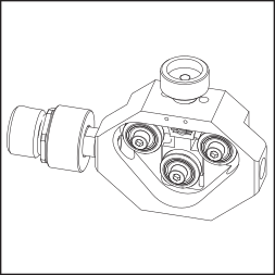
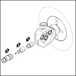
The wire straightener is used for bending or straightening wire electrodes. The wire straightener can accommodate wire electrode diameters of 0.8 mm (0.03 in.) to 1.6 mm (0.06 in.).
Two versions of the wire straightener are available: one for conventional welding systems and one for robot welding systems.
Device concept
The wire straightener is used for bending or straightening wire electrodes. The wire straightener can accommodate wire electrode diameters of 0.8 mm (0.03 in.) to 1.6 mm (0.06 in.).
Two versions of the wire straightener are available: one for conventional welding systems and one for robot welding systems.
Scope of supply
Conventional: |
| Robot: |
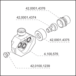 |
| 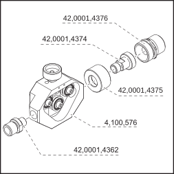 |
Not shown:
| Not shown:
|
Configuration options
- Depending on the routing of the wire electrode before the wire straightener, the wire straightener is used to increase or reduce the wire electrode's degree of bend.
- Depending on how the wire straightener is installed (contact roller above or below), the wire electrode's degree of bend is either increased or decreased.
- Depending on the requirement - contact roller above or below - the positions of the wire run-off plate and the inlet nozzle can be interchanged.
Conventional: |
|
| Robot: | |
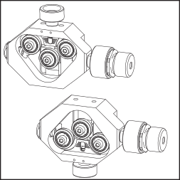 Contact roller above/below |
|
| 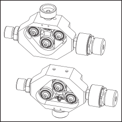 Contact roller above/below | |
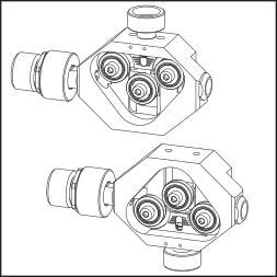 Interchanging wire run-off plate and inlet nozzle positions |
|
| 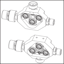 Interchanging wire run-off plate and inlet nozzle positions |
Safety
Safety
Observe the following safety rules for all work described in this document.
WARNING!
Danger due to incorrect operation and incorrectly performed work.
This can result in serious injury and damage to property.
All the work and functions described in this document must only be carried out by trained and qualified personnel.
Read and understand this document.
Read and understand all documents for the system components, especially the safety rules.
WARNING!
Danger from electric current.
This can result in serious injury and damage to property.
Before starting work:
turn the power source mains switch to the "O" position
disconnect the power source from the mains
ensure that the power source remains disconnected from the mains until all work has been completed
After opening the device, use a suitable measuring instrument to check that electrically charged components (e.g. capacitors) have been discharged.
CAUTION!
Risk from wire electrode emerging at speed.
This can result in serious injury and damage to property.
If the welding system contains an unreeling wire-feed unit, also carry out the following actions before starting work:
turn the mains switch of the unreeling wire-feed unit to the "O" position
disconnect the unreeling wire-feed unit from the mains
ensure that the unreeling wire-feed unit remains disconnected from the mains until all work has been completed
CAUTION!
Risk of scalding by hot system components.
This can result in severe scalds.
Before starting work, allow all hot system components to cool down to room temperature (+25 °C, +77 °F). For example:
coolant
water-cooled system components
wire-feed unit drive motor
Safety
Observe the following safety rules for all work described in this document.
WARNING!
Danger due to incorrect operation and incorrectly performed work.
This can result in serious injury and damage to property.
All the work and functions described in this document must only be carried out by trained and qualified personnel.
Read and understand this document.
Read and understand all documents for the system components, especially the safety rules.
WARNING!
Danger from electric current.
This can result in serious injury and damage to property.
Before starting work:
turn the power source mains switch to the "O" position
disconnect the power source from the mains
ensure that the power source remains disconnected from the mains until all work has been completed
After opening the device, use a suitable measuring instrument to check that electrically charged components (e.g. capacitors) have been discharged.
CAUTION!
Risk from wire electrode emerging at speed.
This can result in serious injury and damage to property.
If the welding system contains an unreeling wire-feed unit, also carry out the following actions before starting work:
turn the mains switch of the unreeling wire-feed unit to the "O" position
disconnect the unreeling wire-feed unit from the mains
ensure that the unreeling wire-feed unit remains disconnected from the mains until all work has been completed
CAUTION!
Risk of scalding by hot system components.
This can result in severe scalds.
Before starting work, allow all hot system components to cool down to room temperature (+25 °C, +77 °F). For example:
coolant
water-cooled system components
wire-feed unit drive motor
Fitting the OPT/i WF wire straightener
Preparing the OPT/i WF wire straightener for installation
If necessary, change the position of the inlet nozzle as follows.
Conventional: |
| Robot: |
1 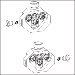 |
| 1 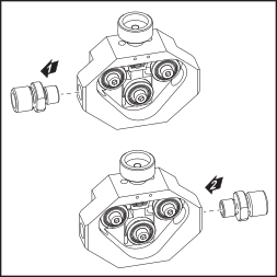 |
Preparing the OPT/i WF wire straightener for installation
If necessary, change the position of the inlet nozzle as follows.
Conventional: |
| Robot: |
1 |
| 1 |
Fitting the OPT/i WF wire straightener
Conventional
1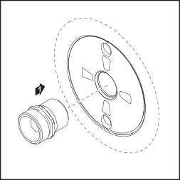
2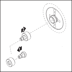
3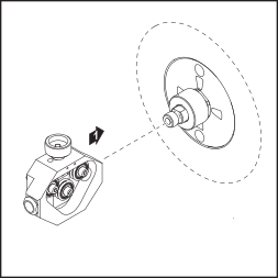
Robot
1
2
3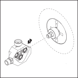
Fitting optional extras
Fitting QuickConnect (conventional)
NOTE!
When fitting the QuickConnect option, follow the instructions in document 42,0410,2010.
1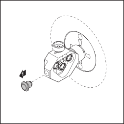
2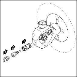
Fitting QuickConnect (conventional)
NOTE!
When fitting the QuickConnect option, follow the instructions in document 42,0410,2010.
1
2
Fitting optional equipment (robot)
NOTE!
When fitting the QuickConnect option, follow the instructions in document 42,0410,2010.
1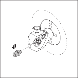
2