Safety
Proper use
The MIG/MAG manual welding torch is intended solely for MIG/MAG welding in manual applications.
Any use above and beyond this purpose is deemed improper. The manufacturer shall not be held liable for any damage arising from such usage.
- Carefully reading and following all the instructions given in the operating instructions
- Performing all stipulated inspection and maintenance work.
Safety
WARNING!
Danger from incorrect operation and work that is not carried out properly.
This can result in serious personal injury and damage to property.
All the work and functions described in this document must only be carried out by technically trained and qualified personnel.
Read and understand this document in full.
Read and understand all safety rules and user documentation for this device and all system components.
WARNING!
Danger from electrical current.
This can result in serious personal injury and damage to property.
Before starting work, switch off all devices and components involved and disconnect them from the grid.
Secure all devices and components involved so they cannot be switched back on.
WARNING!
Danger from electric current due to defective system components and incorrect operation.
This can result in serious personal injury and damage to property.
All cables, leads and hosepacks must always be securely connected, undamaged and correctly insulated.
Only use adequately dimensioned cables, leads and hosepacks.
WARNING!
Risk of coolant escaping.
This can result in serious personal injury and damage to property.
When disconnecting a welding torch from the cooling unit or other system components, always seal the coolant hoses using the plastic seal attached to the torch.
WARNING!
Danger due to hot system components and/or equipment.
Can result in serious burns or scalding.
Before starting work, allow all hot system components and/or equipment to cool to +25°C/+77°F (e.g., coolant, water-cooled system components, wirefeeder drive motor, etc.)
Wear suitable protective equipment (e.g., heat-resistant gloves, safety goggles, etc.) if cooling down is not possible.
WARNING!
Danger from contact with toxic welding fumes.
This can result in serious personal injuries.
Always extract welding fumes.
Ensure an adequate supply of fresh air. Ensure that there is a ventilation rate of at least 20 m³ (169070.1 US gi) per hour at all times.
If in doubt, a safety engineer should be commissioned to check the pollution level in the workplace.
CAUTION!
Danger from operation without coolant.
This can result in damage to property.
Never operate water-cooled welding torches without coolant.
During welding, ensure that the coolant is circulating correctly – this will be the case for Fronius cooling units if a regular return flow of coolant can be seen in the coolant container of the cooling unit.
The manufacturer will not be liable for any damages due to non-observance of the above mentioned points. All claims against the warranty are void.
Danger from welding fumes
WARNING!
Danger from the fumes produced during welding, which contain harmful gases and vapours.
These can cause severe damage to health.
A welding operation is not permitted without an extraction unit that is switched on.
Under certain circumstances, the sole use of a fume extraction torch is not sufficient.
In this case, install an additional extractor to reduce the pollution level in the workplace.
If in doubt, a safety engineer should be commissioned to check the pollution level in the workplace.
MTG d, MTW d, MHP d - General
Up/Down function

- Select one of the following parameters on the power source:
- Wire feed speed
- Job number
- Set the parameters using the Up/Down function
IMPORTANT! In the "MIG/MAG Standard Synergic and Pulse Synergic Welding" operating modes, extra parameters can be set.
Up/Down function
- Select one of the following parameters on the power source:
- Wire feed speed
- Job number
- Set the parameters using the Up/Down function
IMPORTANT! In the "MIG/MAG Standard Synergic and Pulse Synergic Welding" operating modes, extra parameters can be set.
JobMaster function
IMPORTANT! Coded messages can appear on the JobMaster.
These correspond to the service code displayed on the control panel at the same time (see the "Troubleshooting" section of the power source operating instructions).
SynchroPulse (option) - no symbol lights up on the JobMaster (see the "MIG/MAG welding" section of the power source operating instructions).
1
2
3
4
5
MTG 400d K4, MTW 500d K4 - General
General

The MTG 400d K4 and MTW 500d K4 fume extraction torches capture the harmful welding fumes directly at source.
The welding fumes are extracted, before they get into the welder's breathing zone.
Legal specified values for the maximum workplace concentration (MAK) are adhered to or undercut.
General
The MTG 400d K4 and MTW 500d K4 fume extraction torches capture the harmful welding fumes directly at source.
The welding fumes are extracted, before they get into the welder's breathing zone.
Legal specified values for the maximum workplace concentration (MAK) are adhered to or undercut.
Standard values for extraction units
The extraction unit for the fume extraction torch must comply with the following specifications:
Suction power | Approx. 100 m3/h |
Negative pressure values | Between 0.05 and 0.2 bar |
Air chamber
The quantity of extracted welding fumes can be continuously controlled between 10 and 100% using the air chamber during the welding process.
1
2
IMPORTANT! Regulation of the extracted welding fume quantity is required if the shielding gas is extracted with the welding fumes (e.g. when welding in a corner position).
Up/Down function

Fitting wearing parts to the torch neck
MTG d, MTW d - Fitting wearing parts to the torch body
1
2
3
| ** | Screw on and tighten the gas nozzle as far as it will go |
MTG d, MTW d - Fitting wearing parts to the torch body
1
2
3
| ** | Screw on and tighten the gas nozzle as far as it will go |
MTG 400d K4, MTW 500d K4 - Fitting wearing parts
1
2
3
** Screw on and tighten the gas nozzle as far as it will go
4
Fit the extraction nozzle
Fitting the ML torch body to the MHP hosepack
Assembling the Multilock welding torch
NOTE!
Risk of damage to the welding torch. Always tighten the union nut on the torch body as far as it will go.
NOTE!
In the case of water-cooled welding torches, increased resistance may arise when tightening the union nut due to the construction of the welding torch. This is normal. Always tighten the union nut on the torch body as far as it will go.
NOTE!
Before fitting a torch body, ensure that the interface between the torch body and the hosepack is clean and undamaged.
1
NOTE!
The torch body is in the 0° position when the dowel pin (A) on the hosepack engages in the locating hole (B) in the torch body.
2
3
| * | Ensure that the union nut is tightened as far as it will go. |
Fitting the inner liners
Checking the clamping nipple

* Check the clamping nipple before commissioning and whenever the inner liner is changed. To do so, carry out a visual inspection:
- Left: brass clamping nipple with seal ring. You cannot see through the seal ring.
- Right: silver clamping nipple with see-through bushing
NOTE!
Incorrect or defective clamping nipple in push applications
Causes gas loss and poor weld properties
use brass clamping nipples to minimise gas loss
check that the seal ring is intact
NOTE!
Incorrect clamping nipple in push-pull applications
Tangled wire and increased abrasion in the inner liner when using a clamping nipple with seal ring
use silver clamping nipple to facilitate wirefeeding
Checking the clamping nipple
* Check the clamping nipple before commissioning and whenever the inner liner is changed. To do so, carry out a visual inspection:
- Left: brass clamping nipple with seal ring. You cannot see through the seal ring.
- Right: silver clamping nipple with see-through bushing
NOTE!
Incorrect or defective clamping nipple in push applications
Causes gas loss and poor weld properties
use brass clamping nipples to minimise gas loss
check that the seal ring is intact
NOTE!
Incorrect clamping nipple in push-pull applications
Tangled wire and increased abrasion in the inner liner when using a clamping nipple with seal ring
use silver clamping nipple to facilitate wirefeeding
Fitting the steel inner liner
1
2
3
F++, F:
4
5
Euro:
6
7
Fitting the plastic inner liner (F, F++)
1
2
3
4
Fitting the plastic inner liner (Fronius connection with wirefeeding nozzle)
NOTE!
Round off the end of the wire electrode before feeding it in.
Applicable for Teflon liners, combination liners and Graphite liners
1
2
3
4
5
Fitting the plastic inner liner (Euro)
1
2
3
4
* Infeed tube option (42,0001,5421)
5
6
Start-up
Connecting the welding torch
1
| * | LocalNet plug (Standard or Up/Down welding torches) |
| ** | JobMaster plug (JobMaster welding torches) |
1
| * | LocalNet plug (Standard or Up/Down welding torches) |
| ** | JobMaster plug (JobMaster welding torches) |
Connecting the welding torch
1
| * | LocalNet plug (Standard or Up/Down welding torches) |
| ** | JobMaster plug (JobMaster welding torches) |
1
| * | LocalNet plug (Standard or Up/Down welding torches) |
| ** | JobMaster plug (JobMaster welding torches) |
Connecting the extractor

1Connect the hose for the extractor corresponding to the standard values for extraction units to the extraction unit
Twisting the Multilock welding torch body
CAUTION!
Risk of burns from hot coolant and hot torch body.
Before carrying out any work, allow the coolant and torch body to cool to room temperature (+25°C, +77°F).
1
2
3
4
| * | Ensure that the union nut is tightened as far as it will go. |
Changing the torch body on a Multilock welding torch
CAUTION!
Risk of burns from hot coolant and hot torch body.
This can result in severe scalds.
Before carrying out any work, allow the coolant and torch body to cool to room temperature (+25°C, +77°F).
NOTE!
Some coolant will always remain in the torch body.
Only remove the torch body with the gas nozzle pointing downwards.
NOTE!
Before fitting a torch body, ensure that the interface between the torch body and the hosepack is clean and undamaged.
1
2
NOTE!
The torch body is in the 0° position when the dowel pin (A) on the hosepack engages in the locating hole (B) in the torch body.
3
4
| * | Ensure that the union nut is tightened as far as it will go. |
Prisma holder for machine welding torch

Ensure that the machine welding torch to be worked on is only ever clamped in a suitable Prisma holder.
Care and maintenance
General
Regular preventive maintenance of the welding torch is essential if trouble-free operation is to be ensured. The welding torch is subjected to high temperatures and heavy soiling. The welding torch therefore requires more frequent maintenance than other components in the welding system.

CAUTION!
Risk of damage from improper handling of the welding torch.
This can result in severe damage to property.
Do not strike the welding torch on hard objects.
Avoid scoring and scratches on the contact tip.
Do not bend the torch body under any circumstances.
General
Regular preventive maintenance of the welding torch is essential if trouble-free operation is to be ensured. The welding torch is subjected to high temperatures and heavy soiling. The welding torch therefore requires more frequent maintenance than other components in the welding system.
CAUTION!
Risk of damage from improper handling of the welding torch.
This can result in severe damage to property.
Do not strike the welding torch on hard objects.
Avoid scoring and scratches on the contact tip.
Do not bend the torch body under any circumstances.
Recognising faulty wearing parts

- Insulating parts
- Burned-off outside edges, notches
- Nozzle fittings
- Burned-off outside edges, notches
- Heavily covered in welding spatter
- Spatter guard
- Burned-off outside edges, notches
- Contact tips
- Worn-out (oval) wire entry and wire exit holes
- Heavily covered in welding spatter
- Penetration on the tip of the contact tip
- Gas nozzles
- Heavily covered in welding spatter
- Burned-off outside edges
- Notches
Maintenance at every start-up
- Check wearing parts
- replace faulty wearing parts
- Remove welding spatter from gas nozzle
1
2
| * | Check the gas nozzle, spatter guard and insulation for damage and replace any damaged components. |
- Also at every start-up when using water-cooled welding torches:
- check all coolant connections for tightness (no leaks)
- check that the coolant can flow unhindered
Maintenance every time the wirespool/basket-type spool is changed:
- Clean wirefeeding hose with reduced compressed air
- Recommended: replace the inner liner. Clean the wearing parts before fitting the new inner liner
1
2
Troubleshooting
Troubleshooting
Troubleshooting
No welding current
Power source mains switch is on, indicators on the power source are lit up, shielding gas available
| Cause: | Grounding (earthing) connection is incorrect |
| Remedy: | Establish a proper grounding (earthing) connection |
| Cause: | There is a break in the current cable in the welding torch |
| Remedy: | Replace welding torch |
Nothing happens when the torch trigger is pressed
Power source mains switch is on, indicators on the power source are lit up
| Cause: | The FSC ('Fronius System Connector' central connector) is not plugged in properly |
| Remedy: | Push on the FSC as far as it will go |
| Cause: | Welding torch or welding torch control line is faulty |
| Remedy: | Replace welding torch |
| Cause: | Interconnecting hosepack faulty or not connected properly |
| Remedy: | Connect interconnecting hosepack properly Replace faulty interconnecting hosepack |
| Cause: | Faulty power source |
| Remedy: | Contact After-Sales Service |
No shielding gas
All other functions are OK
| Cause: | Gas cylinder is empty |
| Remedy: | Change the gas cylinder |
| Cause: | Gas pressure regulator is faulty |
| Remedy: | Replace gas pressure regulator |
| Cause: | The gas hose is not connected, or is damaged or kinked |
| Remedy: | Fit gas hose, lay out straight Replace faulty gas hose |
| Cause: | Welding torch is faulty |
| Remedy: | Replace welding torch |
| Cause: | Gas solenoid valve is faulty |
| Remedy: | Contact After-Sales Service (arrange for gas solenoid valve to be replaced) |
Poor weld properties
| Cause: | Incorrect welding parameters |
| Remedy: | Correct settings |
| Cause: | Poor grounding (earthing) connection |
| Remedy: | Ensure good contact to workpiece |
| Cause: | Too little or no shielding gas |
| Remedy: | Check the pressure regulator, gas hose, gas solenoid valve and welding torch shielding gas connection. On gas-cooled welding torches, inspect the gas seals, use a suitable inner liner |
| Cause: | Welding torch is leaking |
| Remedy: | Replace welding torch |
| Cause: | Contact tip is too large or worn out |
| Remedy: | Replace contact tip |
| Cause: | Wrong wire alloy or wrong wire diameter |
| Remedy: | Check wirespool/basket-type spool in use |
| Cause: | Wrong wire alloy or wrong wire diameter |
| Remedy: | Check weldability of the base material |
| Cause: | The shielding gas is not suitable for this wire alloy |
| Remedy: | Use the correct shielding gas |
| Cause: | Unfavourable welding conditions: shielding gas is contaminated (by moisture, air), inadequate gas shield (weld pool "boiling", draughts), contaminants in the workpiece (rust, paint, grease) |
| Remedy: | Optimise the welding conditions |
| Cause: | Shielding gas escaping at clamping nipple |
| Remedy: | Use the correct clamping nipple |
| Cause: | Clamping nipple seal ring defective, shielding gas escaping at clamping nipple |
| Remedy: | Replace clamping nipple to ensure a gas-tight seal |
| Cause: | Welding spatter in the gas nozzle |
| Remedy: | Remove welding spatter |
| Cause: | Turbulence caused by too high a rate of shielding gas flow |
| Remedy: | Reduce shielding gas flow rate, recommended: shielding gas flow rate (l/min) = wire diameter (mm) x 10 (e.g. 16 l/min for 1.6 mm wire electrode) |
| Cause: | Distance between the welding torch and the workpiece too great |
| Remedy: | Reduce the distance between the welding torch and the workpiece (approx. 10 - 15 mm / 0.39 - 0.59 in.) |
| Cause: | Tilt angle of the welding torch is too great |
| Remedy: | Reduce the tilt angle of the welding torch |
| Cause: | Wirefeed components do not match the diameter of the wire electrode/wire electrode material |
| Remedy: | Use the correct wirefeed components |
Poor wirefeeding
| Cause: | Depending on the system, brake force in wirefeeder or power source set too high |
| Remedy: | Reduce the brake force |
| Cause: | Hole in the contact tip is displaced |
| Remedy: | Change the contact tip |
| Cause: | The inner liner or wire-guide insert is defective |
| Remedy: | Check the inner liner and wire-guide insert for kinks, dirt, etc. Change the defective inner liner or wire-guide insert |
| Cause: | The feed rollers are not suitable for the wire electrode being used |
| Remedy: | Use suitable wirefeeder rollers |
| Cause: | Wirefeeder rollers have the wrong contact pressure |
| Remedy: | Optimise contact pressure |
| Cause: | The wirefeeder rollers are soiled or damaged |
| Remedy: | Clean or replace wirefeeder rollers |
| Cause: | Inner liner wrongly fitted or kinked |
| Remedy: | Replace inner liner |
| Cause: | The inner liner has been cut too short |
| Remedy: | Replace the inner liner and cut the new inner liner to the correct length |
| Cause: | Wire electrode worn due to excessive contact pressure on the wirefeeder rollers |
| Remedy: | Reduce contact pressure on the wirefeeder rollers |
| Cause: | Wire electrode contains impurities or is corroded |
| Remedy: | Use high-quality wire electrode with no impurities |
| Cause: | For steel inner liners: use of uncoated inner liner |
| Remedy: | Use a coated inner liner |
| Cause: | Clamping nipple in wire entry and wire exit area deformed (oval, knocked out), shielding gas escaping at clamping nipple |
| Remedy: | Replace clamping nipple to ensure a gas-tight seal |
The gas nozzle becomes very hot
| Cause: | No thermal dissipation as the gas nozzle is too loose |
| Remedy: | Screw on the gas nozzle as far as it will go |
The welding torch becomes very hot
| Cause: | Only on Multilock welding torches: torch neck union nut is loose |
| Remedy: | Tighten the union nut |
| Cause: | Welding torch operated above the maximum welding current |
| Remedy: | Reduce welding power or use a more powerful welding torch |
| Cause: | The specification of the welding torch is inadequate |
| Remedy: | Observe the duty cycle and loading limits |
| Cause: | Only on water-cooled systems: Inadequate coolant flow |
| Remedy: | Check coolant level, coolant flow, coolant contamination, the routing of the hosepack, etc. |
| Cause: | The tip of the welding torch is too close to the arc |
| Remedy: | Increase stick-out |
Contact tip has a short service life
| Cause: | Incorrect wirefeeder rollers |
| Remedy: | Use correct wirefeeder rollers |
| Cause: | Wire electrode worn due to excessive contact pressure on the wirefeeder rollers |
| Remedy: | Reduce contact pressure on the wirefeeder rollers |
| Cause: | Wire electrode contains impurities/is corroded |
| Remedy: | Use high-quality wire electrode with no impurities |
| Cause: | Uncoated wire electrode |
| Remedy: | Use wire electrode with suitable coating |
| Cause: | Wrong dimension of contact tip |
| Remedy: | Use a contact tip of the correct dimension |
| Cause: | Duty cycle of welding torch has been exceeded |
| Remedy: | Shorten the duty cycle or use a more powerful welding torch |
| Cause: | Contact tip has overheated. No thermal dissipation as the contact tip is too loose |
| Remedy: | Tighten the contact tip |
NOTE!When using CrNi, the contact tip may be subject to a higher degree of wear due to the nature of the surface of the CrNi wire electrode. | |
Torch trigger malfunction
| Cause: | Defective plug connection between welding torch and power source |
| Remedy: | Establish proper plug connections / have power source or welding torch serviced |
| Cause: | Build up of dirt between torch trigger and torch trigger housing |
| Remedy: | Clean away the dirt |
| Cause: | Control line is faulty |
| Remedy: | Contact After-Sales Service |
Weld seam porosity
| Cause: | Spattering in the gas nozzle causing inadequate gas shield for weld seam |
| Remedy: | Remove welding spatter |
| Cause: | Holes in gas hose or hose is not connected properly |
| Remedy: | Replace gas hose |
| Cause: | O-ring on central connector has been cut or is faulty |
| Remedy: | Replace O-ring |
| Cause: | Moisture/condensation in the gas line |
| Remedy: | Dry gas line |
| Cause: | Gas flow is either too high or too low |
| Remedy: | Correct gas flow |
| Cause: | Insufficient gas flow at start or end of welding |
| Remedy: | Increase gas pre-flow and gas post-flow |
| Cause: | Rusty or poor quality wire electrode |
| Remedy: | Use high-quality wire electrode with no impurities |
| Cause: | Applies to gas-cooled welding torches: gas is escaping through a non-insulated inner liner |
| Remedy: | Use only insulated inner liners with gas-cooled welding torches |
| Cause: | Too much parting agent applied |
| Remedy: | Remove excess parting agent/apply less parting agent |
| Cause: | Too much suction |
| Remedy: | Reduce suction |
Too little suction
| Cause: | Hole(s) in the extraction hose |
| Remedy: | Replace extraction hose |
| Cause: | Extraction unit filter blocked |
| Remedy: | Replace extraction unit filter |
| Cause: | Air passages blocked |
| Remedy: | Remove blockages |
| Cause: | Extraction capacity of the extraction unit too low; OPT/i FumeEx configured incorrectly |
| Remedy: | Use an extraction unit with a higher extraction capacity; increase the extraction capacity |
Technical data
General
- for manually-operated welding torches: 113 V
- for mechanically-driven welding torches: 141 V
- Umax = 5 V
- Imax = 10 mA
The torch trigger may only be operated in accordance with the technical data.
The product conforms to the requirements of IEC 60974-7 / - 10 Class A.
General
- for manually-operated welding torches: 113 V
- for mechanically-driven welding torches: 141 V
- Umax = 5 V
- Imax = 10 mA
The torch trigger may only be operated in accordance with the technical data.
The product conforms to the requirements of IEC 60974-7 / - 10 Class A.
Gas-cooled welding torch - MTG 250d - 500d
MTG 250d | MTG 320d | MTG 400d | MTG 500d | |||
|---|---|---|---|---|---|---|
I (amp.) 10 min/40°C | 40% D.C.* 250 | 40% D.C.* 320 | 40% D.C.* 400 | 40% D.C.* 500 | ||
I (amp.) 10 min/40°C | 40% D.C.* 200 | 40% D.C.* 260 | 40% D.C.* 320 | 40% D.C.* 400 | ||
 | [mm (in.)] | 0.8-1.2 (0.032-0.047) | 0.8-1.6 (0.032-0.063) | 1.0-1.6 (0.039-0.063) | 1.0-1.6 (0.039-0.063) | |
 | [m (ft.)] | 3,5 / 4,5 | 3,5 / 4,5 | 3,5 / 4,5 | 3,5 / 4,5 | |
* D.C. = Duty cycle | ||||||
Gas-cooled torch body - MTB 250i, 320i, 330i, 400i, 550i G ML
| MTB 250i G ML | MTB 320i G ML | MTB 330i G ML | |
|---|---|---|---|---|
I (ampere) 10 min/40°C | 40 % ED* 250 | 40 % ED* 320 | 40 % ED* 330 | |
| [mm (in.)] | 0.8-1.2 (0.032-0.047) | 0.8-1.6 (0.032-0.063) | 0.8-1.6 (0.032-0.063) |
* ED = Duty cycle | ||||
| MTB 400i G ML | MTB 550i G ML | |
|---|---|---|---|
I (ampere) 10 min/40°C | - | 30 % ED* 550 | |
I (ampere) 10 min/40°C | - | 30 % ED* 520 | |
I (ampere) 10 min/40°C | 40 % ED* 400 | - | |
| [mm (in.)] | 0.8-1.6 (0.032-0.063) | 0.8-1.6 (0.032-0.063) |
* ED = Duty cycle | |||
Gas-cooled hosepack - MHP 400d G ML
| MHP 400d G ML | ||
|---|---|---|---|
I (ampere) 10 min/40 °C | 40% D.C.* 400 | ||
I (ampere) 10 min/40 °C | 40% D.C.* 320 | ||
| [mm (in.)] | 0.8-1.6 (0.032-0.063) | |
| [m (ft.)] | 3.35 / 4.35 (11 / 14) | |
* D.C. = Duty cycle | |||
Gas-cooled hosepack - MHP 500d G ML M
| MHP 500d G ML M | ||
|---|---|---|---|
I (amp.) 10 min/40 °C | 40% D.C.* 500 | ||
I (amp.) 10 min/40 °C | 40% D.C.* 400 | ||
| [mm (in.)] | 0.8-1.6 (0.032-0.063) | |
| [m (ft.)] | 1.35 / 2.35 / 3.35 (4.4 / 7.7 / 14) | |
* D.C. = Duty cycle | |||
Water-cooled welding torch - MTW 250d - 700d
MTW 250d | MTW 400d | MTW 500d | MTW 700d | |||
|---|---|---|---|---|---|---|
I (ampere) 10 min/40°C | 100% D.C.* 250 | 100% D.C.* 400 | 100% D.C.* 500 | 100% D.C.* 700 | ||
I (ampere) 10 min/40°C | 100% D.C.* 200 | 100% D.C.* 320 | 100% D.C.* 400 | 100% D.C.* 560 | ||
| [mm (in.)] | 0.8-1.2 (0.032-0.047) | 0.8-1.6 (0.032-0.063) | 0.8-1.6 (0.032-0.063) | 0.8-1.6 (0.032-0.063) | |
Qmin |  | [l/min (gal./min)] | 1 (.26) | 1 (.26) | 1 (.26) | 1 (.26) |
Pmin | | [W]** | 500 (3,5 m) | 800 (3,5 m) | 1400 (3,5 m) | 1800 (3,5 m) |
Pmin | | [bar (psi.)] | 3 (43) | 3 (43) | 3 (43) | 3 (43) |
Pmax | | [bar (psi.)] | 5 (72) | 5 (72) | 5 (72) | 5 (72) |
| [m (ft.)] | 3,5 / 4,5 | 3,5 / 4,5 | 3,5 / 4,5 | 3,5 / 4,5 | |
* D.C. = Duty cycle | ||||||
** Lowest cooling power according to IEC 60974-2 | ||||||
Water-cooled torch body - MTB 250i, 330i, 400i, 500i, 700i W ML
MTB 250i W ML | MTB 330i W ML | MTB 400i W ML | MTB 500i W ML | |||
|---|---|---|---|---|---|---|
I (ampere) 10 min/40°C | 100 % ED* 250 | 100 % ED* 330 | 100 % ED* 400 | 100 % ED* 500 | ||
| [mm (in.)] | 0.8-1.2 | 0.8-1.6 | 0.8-1.6 | 1.0-1.6 | |
Qmin | | [l/min (gal./min)] | 1 (0.26) | 1 (0.26) | 1 (0.26) | 1 (0.26) |
* ED = Duty cycle | ||||||
MTB 700i W ML | |||
|---|---|---|---|
I (ampere) 10 min/40°C | 100 % ED* 700 | ||
| [mm (in.)] | 1.0-1.6 | |
Qmin | | [l/min (gal./min)] | 1 (0.26) |
* ED = Duty cycle | |||
Water-cooled hosepack - MHP 500d, 700d W ML
|
| MHP 500d W ML | MHP 700d W ML | |
|---|---|---|---|---|
I (ampere) 10 min/40 °C | 100% D.C.* 500 | 100% D.C.* 700 | ||
I (ampere) 10 min/40 °C | 100% D.C.* 400 | 100% D.C.* 560 | ||
| [mm (in.)] | 0.8-1.6 (0.032-0.063) | 0.8-1.6 (0.032-0.063) | |
| [m (ft.)] | 3.35 / 4.35 (11 / 14) | 3.35 / 4.35 (11 / 14) | |
Pmin | | [W]** | 1400 / 1700 | 1800 / 2200 |
Qmin | | [l/min (gal./min.)] | 1 (.26) | 1 (.26) |
Pmin | | [bar (psi.)] | 3 (43) | 3 (43) |
Pmax | | [bar (psi.)] | 5 (72) | 5 (72) |
* D.C. = Duty cycle | ||||
** Lowest cooling power according to IEC 60974-2 | ||||
Water-cooled hosepack - MHP 700d W ML M
|
| MHP 700d W ML M | ||
|---|---|---|---|---|
I (ampere) 10 min/40 °C | 100% D.C.* 700 | |||
I (ampere) 10 min/40 °C | 100% D.C.* 560 | |||
| [mm (in.)] | 0.8-1.6 (0.032-0.063) | ||
| [m (ft.)] | 1.35 / 2.35 / 3.35 (4.4 / 7.7 / 14) | ||
Pmin | | [W]** | 1100 / 1450 / 1800 | |
Qmin | | [l/min (gal./min)] | 1 (.26) | |
Pmin | | [bar (psi.)] | 3 (43) | |
Pmax | | [bar (psi.)] | 5 (72) | |
* D.C. = Duty cycle | ||||
** Lowest cooling power according to IEC 60974-2 | ||||
MTG 400d K4
| MTG 400d K4 | ||
|---|---|---|---|
I (ampere) 10 min/40 °C | 40% D.C.* 400 | ||
| [mm (in.)] | 0.8-1.6 (0.032-0.063) | |
| [m (ft.)] | 4.5 (15) | |
* D.C. = Duty cycle | |||
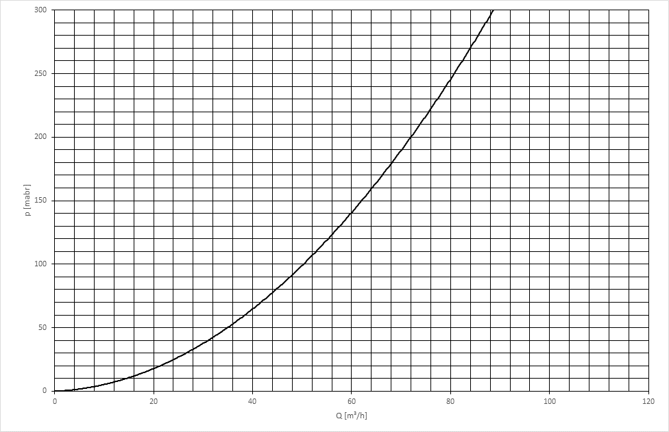
MTG 400d K4 extraction characteristic

MTW 500d K4
|
| MTW 500d K4 | ||
|---|---|---|---|---|
I (ampere) 10 min/40 °C | 100 % D.C.* 500 | |||
| [mm (in.)] | 0,8-1,6 (.032-.063) | ||
| [m (ft.)] | 4,5 (15) | ||
Pmax | | [W]** | 1700 | |
Qmin | | [l/min | 1 (26) | |
pmin | | [bar (psi.)] | 3 (43) | |
pmax | | [bar (psi.)] | 5 (72) | |
* D.C. = Duty cycle | ||||
** Lowest cooling power according to standard IEC 60974-2 | ||||
MTW 500d K4 extraction characteristic