Safety rules
Explanation of safety notices
DANGER!
Indicates immediate danger.
If not avoided, death or serious injury will result.
WARNING!
Indicates a potentially hazardous situation.
If not avoided, death or serious injury may result.
CAUTION!
Indicates a situation where damage or injury could occur.
If not avoided, minor injury and/or damage to property may result.
NOTE!
Indicates a risk of flawed results and possible damage to the equipment.
Explanation of safety notices
DANGER!
Indicates immediate danger.
If not avoided, death or serious injury will result.
WARNING!
Indicates a potentially hazardous situation.
If not avoided, death or serious injury may result.
CAUTION!
Indicates a situation where damage or injury could occur.
If not avoided, minor injury and/or damage to property may result.
NOTE!
Indicates a risk of flawed results and possible damage to the equipment.
General
- injury or death to the operator or a third party,
- damage to the device and other material assets belonging to the operating company,
- inefficient operation of the device.
- be suitably qualified,
- have sufficient knowledge of welding and
- read and follow these operating instructions carefully.
The operating instructions must always be at hand wherever the device is being used. In addition to the operating instructions, attention must also be paid to any generally applicable and local regulations regarding accident prevention and environmental protection.
All safety and danger notices on the device- must be in a legible state,
- must not be damaged,
- must not be removed,
- must not be covered, pasted or painted over.
For the location of the safety and danger notices on the device, refer to the section headed "General" in the operating instructions for the device.
Before switching on the device, rectify any faults that could compromise safety.
This is for your personal safety!
Proper use
The device is to be used exclusively for its intended purpose.
Any use above and beyond this purpose is deemed improper. The manufacturer shall not be held liable for any damage arising from such usage.
- carefully reading and following all the instructions given in the operating instructions
- studying and obeying all safety and danger notices carefully
- performing all stipulated inspection and servicing work.
The device is designed for use in industry and the workshop. The manufacturer accepts no responsibility for any damage caused through use in a domestic setting.
The manufacturer likewise accepts no liability for unexpected or incorrect results.
Environmental conditions
Operation or storage of the device outside the stipulated area will be deemed as not in accordance with the intended purpose. The manufacturer shall not be held liable for any damage arising from such usage.
Ambient air temperature range:- during operation: 0 °C to + 40 °C (32 °F to 104 °F)
- during transport and storage: 0 °C to + 40 °C (32 °F to 104 °F)
- up to 50% at 40 °C (104 °F)
- up to 90% at 20 °C (68 °F)
The surrounding air must be free from dust, acids, corrosive gases or substances, etc.
Can be used at altitudes up to 2000 m (6561 ft. 8.16 in.)
Obligations of the operator
- are familiar with the fundamental instructions regarding safety at work and accident prevention and have been instructed in how to use the device
- have read and understood these operating instructions, especially the section "safety rules", and have confirmed as much with their signatures
- are trained to produce the required results.
Checks must be carried out at regular intervals to ensure that operators are working in a safety-conscious manner.
Obligations of personnel
- to observe the basic instructions regarding safety at work and accident prevention
- to read these operating instructions, especially the "Safety rules" section and sign to confirm that they have understood them and will follow them.
Before leaving the workplace, ensure that people or property cannot come to any harm in your absence.
Mains connection
Devices with a higher rating may affect the energy quality of the mains due to their current consumption.
This may affect a number device types in terms of:- Connection restrictions
- Criteria with regard to the maximum permissible mains impedance *)
- Criteria with regard to the minimum short-circuit power requirement *)
*) at the interface with the public grid
see "Technical data"
In this case, the plant operator or the person using the device should check whether the device may be connected, where appropriate by discussing the matter with the power supply company.
IMPORTANT! Ensure that the mains connection is earthed properly
Protecting yourself and others
For your personal safety, take the following precautions:
Use suitable protective clothing
Protective clothing refers to a variety of different items. Operators should:- protect their eyes with the specified protective goggles;
- wear stout footwear that provides insulation even in wet conditions;
- protect their hands by wearing suitable gloves (electrically insulated, heat-proof, protection from cut injuries);
- wear ear protection to reduce the harmful effects of noise and to prevent injury.
- warn them of all the dangers
- provide suitable protective equipment or
- erect suitable safety screens/curtains
Risks from mains current and welding current
An electric shock is potentially life threatening and can be fatal.
Do not touch live parts either inside or outside the device.
Make sure that you and others are protected with an adequately insulated, dry base or cover for the earth or ground potential. This base or cover must extend over the entire area between the body and the earth or ground potential.
All cables and leads must be secured, undamaged, insulated and adequately dimensioned. Replace loose connections and scorched, damaged or inadequately dimensioned cables and leads immediately.
Use the handle to ensure the power connections are tight before every use.
In the case of power cables with a bayonet connector, rotate the power cable around the longitudinal axis by at least 180° and pre-load.
Do not wrap cables or leads around the body or parts of the body.
Arrange for the mains cable to be checked regularly by a qualified electrician to ensure the ground conductor is functioning properly.
The device must only be operated on a mains supply with a ground conductor and a socket with a ground conductor contact.
If the device is operated on a grid without a ground conductor and in a socket without a ground conductor contact, this will be deemed gross negligence. The manufacturer shall not be held liable for any damage arising from such usage.
If necessary, provide an adequate earth connection for the workpiece.
Switch off unused devices.
Before working on the device, switch it off and pull out the mains plug.
Attach a clearly legible and easy-to-understand warning sign to the device to prevent anyone from plugging the mains plug back in and switching it on again.
After opening the device:- Discharge all live components
- Ensure that all components in the device are de-energised
If work on live parts is required, appoint a second person to switch off the main switch at the right moment.
EMC Device Classifications
- Are only designed for use in industrial settings
- Can cause line-bound and radiated interference in other areas
- Satisfy the emissions criteria for residential and industrial areas. This is also true for residential areas in which the energy is supplied from the public low-voltage mains.
EMC device classification as per the rating plate or technical data.
EMC measures
In certain cases, even though a device complies with the standard limit values for emissions, it may affect the application area for which it was designed (e.g. when there is sensitive equipment at the same location, or if the site where the device is installed is close to either radio or television receivers).
If this is the case, then the operator is obliged to take appropriate action to rectify the situation.
- Safety devices
- Network, signal and data transfer lines
- IT and telecommunications devices
- Measuring and calibrating devices
- Mains supply
- If electromagnetic interference arises despite the correct mains connection, additional measures are necessary (e.g. use of a suitable line filter)
- Welding power-leads
- must be kept as short as possible
- must be laid close together (to avoid EMF problems)
- must be kept well apart from other leads
- Equipotential bonding
- Earthing of the workpiece
- If necessary, establish an earth connection using suitable capacitors.
- Shield, if necessary
- Shield other devices nearby
- Shield the entire welding installation
EMF measures
- Effects on the health of persons in the vicinity, e.g. those with pacemakers and hearing aids
- Individuals with pacemakers must seek advice from their doctor before approaching the device or any welding that is in progress
- For safety reasons, maintain as large a distance as possible between the welding power-leads and the head/torso of the welder
- Do not carry welding power-leads and hosepacks over the shoulders or wind them around any part of the body
Specific hazards
- Fans
- Cogs
- Rollers
- Shafts
- Wirespools and welding wires
Do not reach into the rotating cogs of the wire drive or into rotating drive components.
Covers and side panels may only be opened / removed while maintenance or repair work is being carried out.
During operation- Ensure that all covers are closed and all side panels are fitted properly.
- Keep all covers and side panels closed.
The welding wire emerging from the wire speed measuring system poses a high risk of injury (piercing of the hand, injuries to the face and eyes, etc.).
For this reason, always keep the wire speed measuring system away from the head and body and wear suitable protective goggles.
Special provisions apply in areas at risk of fire or explosion
- observe relevant national and international regulations.
Power sources for work in areas with increased electric risk (e.g. near boilers) must carry the "Safety" sign. However, the power source must not be located in such areas.
Use only suitable load-carrying equipment supplied by the manufacturer when transporting devices by crane.
- Hook chains or ropes onto all suspension points provided on the load-carrying equipment.
- Chains and ropes must be at the smallest angle possible to the vertical.
- Remove gas cylinder and wirefeeder (MIG/MAG and TIG devices).
If the device has a carrying strap or handle, this is intended solely for carrying by hand. The carrying strap is not to be used if transporting with a crane, counterbalanced lift truck or other mechanical hoist.
All lifting accessories (straps, handles, chains, etc.) used in connection with the device or its components must be tested regularly (e.g. for mechanical damage, corrosion or changes caused by other environmental factors).
The testing interval and scope of testing must comply with applicable national standards and directives as a minimum.
Danger from shielding gas cylinders
Shielding gas cylinders contain gas under pressure and can explode if damaged. As the shielding gas cylinders are part of the welding equipment, they must be handled with the greatest of care.
Protect shielding gas cylinders containing compressed gas from excessive heat, mechanical impact, slag, naked flames, sparks and arcs.
Mount the shielding gas cylinders vertically and secure according to instructions to prevent them falling over.
Keep the shielding gas cylinders well away from any welding or other electrical circuits.
Never hang a welding torch on a shielding gas cylinder.
Never touch a shielding gas cylinder with an electrode.
Risk of explosion - never attempt to weld a pressurised shielding gas cylinder.
Only use shielding gas cylinders suitable for the application in hand, along with the correct and appropriate accessories (regulator, hoses and fittings). Only use shielding gas cylinders and accessories that are in good condition.
Turn your face to one side when opening the valve of a shielding gas cylinder.
Close the shielding gas cylinder valve if no welding is taking place.
If the shielding gas cylinder is not connected, leave the valve cap in place on the cylinder.
The manufacturer's instructions must be observed as well as applicable national and international regulations for shielding gas cylinders and accessories.
Safety measures at the installation location and during transport
- The maximum permissible tilt angle is 10°.
- Observe relevant national and international regulations.
Use internal directives and checks to ensure that the workplace environment is always clean and clearly laid out.
Only set up and operate the device in accordance with the degree of protection shown on the rating plate.
When setting up the device, ensure there is an all-round clearance of 0.5 m (1 ft. 7.69 in.) to ensure that cooling air can flow in and out freely.
When transporting the device, observe the relevant national and local guidelines and accident prevention regulations. This applies especially to guidelines regarding the risks arising during transport.
After transporting the device, the device must be visually inspected for damage before commissioning. Any damage must be repaired by trained service technicians before commissioning the device.
Safety measures in normal operation
- injury or death to the operator or a third party
- damage to the device and other material assets belonging to the operator
- inefficient operation of the device
Any safety devices that are not functioning properly must be repaired before switching on the device.
Never bypass or disable safety devices.
Before switching on the device, ensure that no one is likely to be endangered.
Check the device at least once a week for obvious damage and proper functioning of safety devices.
Commissioning, maintenance and repair
It is impossible to guarantee that bought-in parts are designed and manufactured to meet the demands made of them, or that they satisfy safety requirements.
- Use only original spare and wearing parts (also applies to standard parts).
- Do not carry out any modifications, alterations, etc. to the device without the manufacturer's consent.
- Components that are not in perfect condition must be replaced immediately.
- When ordering, please give the exact designation and part number as shown in the Spare Parts List, as well as the serial number of your device.
The housing screws provide the ground conductor connection for earthing the housing parts.
Only use original housing screws in the correct number and torque to 3 Nm.
Safety inspection
The manufacturer recommends that a safety inspection of the device is performed at least once every 12 months.
The manufacturer recommends that the power source be calibrated during the same 12-month period.
A safety inspection should be carried out by a qualified electrician- after any changes are made
- after any additional parts are installed, or after any conversions
- after repair, care and maintenance has been carried out
- at least every twelve months.
For safety inspections, follow the appropriate national and international standards and directives.
Further details on safety inspection and calibration can be obtained from your service centre. They will provide you on request with any documents you may require.
Calibration of the calibration system
Regular calibration is required to guarantee the traceability to national or international standards of calibrations performed with this calibration system.
Fronius recommends a 12-month calibration interval. For more information, please contact your Fronius partner.
Disposal
Do not dispose of this device with normal domestic waste! To comply with the European Directive on Waste Electrical and Electronic Equipment and its implementation as national law, electrical equipment that has reached the end of its life must be collected separately and returned to an approved recycling facility. Any device that you no longer require must either be returned to your dealer or given to one of the approved collection and recycling facilities in your area. Ignoring this European Directive may have potentially adverse affects on the environment and your health!
Safety symbol
Devices with the CE mark satisfy the essential requirements of the low-voltage and electromagnetic compatibility directives. Further details can be found in the appendix or the section headed "Technical data" in your documentation.
Data protection
The user is responsible for the safekeeping of any changes made to the factory settings. The manufacturer accepts no liability for any deleted personal settings.
Copyright
Copyright of these operating instructions remains with the manufacturer.
The text and illustrations are all technically correct at the time of printing. We reserve the right to make changes. The contents of the operating instructions shall not provide the basis for any claims whatsoever on the part of the purchaser. If you have any suggestions for improvement, or can point out any mistakes that you have found in the instructions, we will be most grateful for your comments.
General information
General
Device concept
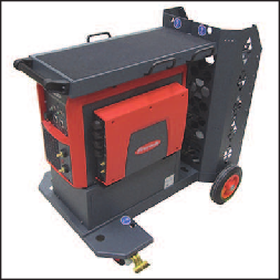
The 2.0 calibration system is designed for calibrating power sources.
All types of Fronius power sources can be calibrated under static load using this system.
Both DC and AC devices can be calibrated.
The calibration system is suitable for quick and easy calibration of the power source in situ.
The calibration system can also be used for servicing to test or check the power sources (e.g. after repairs, troubleshooting, etc.).
General
Device concept
The 2.0 calibration system is designed for calibrating power sources.
All types of Fronius power sources can be calibrated under static load using this system.
Both DC and AC devices can be calibrated.
The calibration system is suitable for quick and easy calibration of the power source in situ.
The calibration system can also be used for servicing to test or check the power sources (e.g. after repairs, troubleshooting, etc.).
Device concept
The 2.0 calibration system is designed for calibrating power sources.
All types of Fronius power sources can be calibrated under static load using this system.
Both DC and AC devices can be calibrated.
The calibration system is suitable for quick and easy calibration of the power source in situ.
The calibration system can also be used for servicing to test or check the power sources (e.g. after repairs, troubleshooting, etc.).
Proper use / intended purpose
The device is only intended to be used for calibrating and testing welding systems and power sources.
Any use above and beyond this purpose is deemed improper. The manufacturer shall not be liable for any damage resulting from such use.
Proper use also includes- carefully reading these Operating Instructions
- following all the instructions and safety rules in these Operating Instructions
- performing all stipulated inspection and maintenance work
The device is designed for use in industry and the workshop. The manufacturer accepts no responsibility for any damage caused through use in a domestic setting.
Crane transport
WARNING!
Danger due to falling device or device parts.
This can result in serious personal injury and damage to property.
Do not walk under the device when it is being suspended in an elevated position or dwell in hazardous locations
Exclusively use load-carrying equipment approved by Fronius
Attach 4 chains or 4 ropes to the four suspension points
Route chains/ropes so they are at the smallest angle possible to the vertical
Check and maintain load-carrying equipment to ensure it adheres to national regulations
WARNING!
Danger due to falling device or device parts.
This can result in serious personal injury and damage to property.
Before moving the crane, make sure that there are no objects on the shelf and in the storage compartments,
Before transporting the crane, close all accessory shutters and lock or secure them.
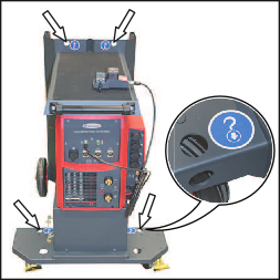
4 suspension points for transporting by crane
Accessories and options
Interface and trolley
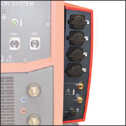
Interface calibration system 4,050,211
+ installation set gas calibration system 4,101,025
+ installation set gas calibration system 4,101,025
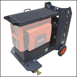
Trolley calibration system 4,077,022
Interface and trolley
Interface calibration system 4,050,211
+ installation set gas calibration system 4,101,025
+ installation set gas calibration system 4,101,025
Trolley calibration system 4,077,022
Accessories
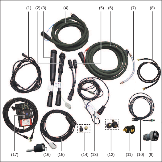
| Item | Description | Item no. |
|---|---|---|
| (1) | 1 x mains cable, 5 m 43,0004,2862 | |
| (2) | 1 x Euro/central connector adapter with Tuchel socket 44,0350,5407 | |
| (3) | 1 x Fronius/central connector adapter 44,0350,4504 | |
| (4) | 1 x (+) power cable with sense lead (red) 43,0004,5883 | |
| (5) | 1 x LocalNet passive splitter 4,100,261 | |
| (6) | 1 x (-) power cable with sense lead (blue) 43,0004,5882 | |
| (7) | 1 x cooling unit bridging hose for use with the Euro/central connector adapter 44,0001,1204 | |
| (8) | 1 x gas hose 1.5 m, 2 x 1/4“ 44,0001,0538 | |
| (9) | Adapter ZA Euro/FSC 44,0350,3329 | |
| (10) | 1 x USB connection cable to PC/laptop 43,0004,5963 | |
| (11) | Socket splitter 70/95 DIX KAB 43,0003,0704 | |
| (12) | 2 x high-current socket to bayonet adapter 42,0001,4482 | |
| (13) | 1 x LocalNet/USB converter 4,101,026 | |
| (14) | 2 x bayonet adapter 25 mm2 to 50 mm2 4,001,549 | |
| (15) | 1 x Tuchel adapter cable 43,0004,5884 | |
| (16) | Adapter ZA FSC-S-G/Euro STD 44,0350,3565 | |
| (17) | 1 x welding wire calibration system 4,050,210 + Connecting cable 5 m 43,0004,5997 |
Further accessories (not pictured)
Description | Item no. |
|---|---|
1 x power adapter | 4,051,091 |
1 x connection cable for gas sensor, 5 m | 43,0004,5914 |
1 x 1.6 m SpeedNet cable | 4,051,021 |
2 x 5 m SpeedNet cable | 4,051,022 |
2 x insulating sleeve adapter | 42,0100,1411 |
1 x 2.5 m 8-pin data cable, PUR | 43,0004,4361 |
1 x LocalNet 6-pin cable with Molex Microfit socket | 43,0004,4850 |
2 x USB Ethernet adapter EU 4306 | 43,0004,5688 |
Options
Designation | Item no. |
|---|---|
Signotec signature pad | 41,0006,0126 |
1.5 m gas hose, 2 x 1/4" | 44,0001,0538 |
5 m gas hose, 2 x 1/4" | 44,0001,0695 |
10 m gas hose, 2 x 1/4" | 44,0001,3423 |
Double nipple 1/4" | 42,0401,0874 |
Gas fitting connection, 1/4" | 44,0450,0281 |
Gas hosepack adapter, external 1/4" - internal 5/8-18 UNF | 42,0001,3540 |
Gas fitting 5 /8" - 8400 + 8411 | 42,0001,6601 |
Removable cable tie, 180 mm | 42,0407,0558 |
Calibration system trolley | 4,077,022 |
TU Car 4 Basic trolley | 4,077,009 |
Required for calibration
Computer & software
- Computer, laptop
- Calibration software
The calibration software can be downloaded from: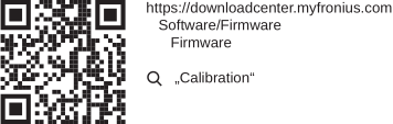
Fronius internal: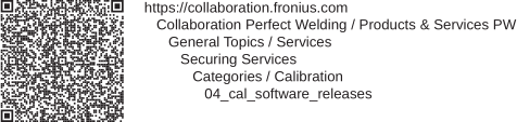
Computer & software
- Computer, laptop
- Calibration software
The calibration software can be downloaded from:
Fronius internal:
Hardware & accessories
- Calibration system 2.0
- Interface calibration system
- Welding wire calibration system
- Accessories calibration system
- Trolley calibration system
Required for calibration of the WeldCube Connector
For the calibration of WeldCube Connector U/I and WeldCube Connector Advanced:
- PoE injector, RJ45 30 W / 802.3at / PoE+ (42,0411,0213)
- M12-X / RJ45 network cable, 5 m (42.0411.0232)
- Voltage measurement adapter
- Smart Device + WeldConnect app
- Power source (e.g. TransSteel 5000, TPS 500i + PowerConnector adapter - Dinse, iWave, etc.)
For the calibration of WeldCube Connector U/I/WFS WSM and WeldCube Connector Advanced + WSM:
- PoE injector, RJ45 30 W / 802.3at / PoE+ (42,0411,0213)
- M12-X / RJ45 network cable, 5 m (42.0411.0232)
- Smart Device + WeldConnect app
- Available TransSteel system components
- 70/95 DIX KAB socket splitter (43,0003,0704)
For the calibration of WeldCube Connector U/I/WFS Euro and WeldCube Connector Advanced + Euro:
- PoE injector, RJ45 30 W / 802.3at / PoE+ (42,0411,0213)
- M12-X / RJ45 network cable, 5 m (42.0411.0232)
- Smart Device + WeldConnect app
- Power source TPS 500i or TransSteel 5000
- Wirefeeder WF 25i / WF 30i or VR 5000, each with adapter-ZA FSC-S-G/Euro STD (44,0350,3565)
- Power sharing cable (only for TPSi)
Controls, connections and mechanical components
Controls and connections on calibration system
Front of device
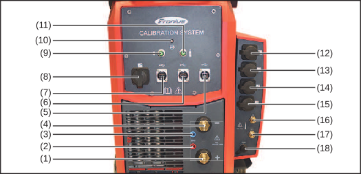
Calibration system 2.0 with interface calibration system
| Item | Description |
|---|---|
| (1) | (+) power connection (red) |
| (2) | (+) sense lead connection socket (red) |
| (3) | (-) sense lead connection socket (blue) |
| (4) | (-) power connection (blue) |
| (5) | USB port computer/laptop |
| (6) | USB port for adapter |
| (7) | USB port for adapter |
| (8) | SpeedNet connection socket |
| (9) | Welding wire calibration system connection socket |
| (10) | Status indicator Lights up green Device is ready Lights up red An error has occurred A description of the error is displayed by the software during the calibration process. |
| (11) | Gas calibration system connection socket |
| (12) | SpeedNet connection socket |
| (13) | SpeedNet connection socket |
| (14) | SpeedNet connection socket |
| (15) | SpeedNet connection socket |
| (16) | Gas IN connection socket (option) |
| (17) | Gas OUT connection socket (option) |
| (18) | Data connection socket (option of connecting to the calibration system) |
Controls and connections on calibration system
Front of device
Calibration system 2.0 with interface calibration system
| Item | Description |
|---|---|
| (1) | (+) power connection (red) |
| (2) | (+) sense lead connection socket (red) |
| (3) | (-) sense lead connection socket (blue) |
| (4) | (-) power connection (blue) |
| (5) | USB port computer/laptop |
| (6) | USB port for adapter |
| (7) | USB port for adapter |
| (8) | SpeedNet connection socket |
| (9) | Welding wire calibration system connection socket |
| (10) | Status indicator Lights up green Device is ready Lights up red An error has occurred A description of the error is displayed by the software during the calibration process. |
| (11) | Gas calibration system connection socket |
| (12) | SpeedNet connection socket |
| (13) | SpeedNet connection socket |
| (14) | SpeedNet connection socket |
| (15) | SpeedNet connection socket |
| (16) | Gas IN connection socket (option) |
| (17) | Gas OUT connection socket (option) |
| (18) | Data connection socket (option of connecting to the calibration system) |
Front of device
Calibration system 2.0 with interface calibration system
| Item | Description |
|---|---|
| (1) | (+) power connection (red) |
| (2) | (+) sense lead connection socket (red) |
| (3) | (-) sense lead connection socket (blue) |
| (4) | (-) power connection (blue) |
| (5) | USB port computer/laptop |
| (6) | USB port for adapter |
| (7) | USB port for adapter |
| (8) | SpeedNet connection socket |
| (9) | Welding wire calibration system connection socket |
| (10) | Status indicator Lights up green Device is ready Lights up red An error has occurred A description of the error is displayed by the software during the calibration process. |
| (11) | Gas calibration system connection socket |
| (12) | SpeedNet connection socket |
| (13) | SpeedNet connection socket |
| (14) | SpeedNet connection socket |
| (15) | SpeedNet connection socket |
| (16) | Gas IN connection socket (option) |
| (17) | Gas OUT connection socket (option) |
| (18) | Data connection socket (option of connecting to the calibration system) |
Rear of device (without trolley)
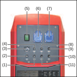
| Item | Designation |
|---|---|
| (1) | F5 fuse (2 A slow-blow) 24 V PLC fuse protection |
| (2) | F4 fuse (2 A slow-blow) 24 V PLC fuse protection |
| (3) | Mains cable connection |
| (4) | Main fuse for the device F1 (4 A slow-blow) |
| (5) | Mains switch |
| (6) | 230 V socket (for 230 V power supply) |
| (7) | 230 V socket (for 230 V power supply) |
| (8) | F2 fuse (1 A slow-blow) AC voltage measurement fuse protection |
| (9) | F3 fuse (1 A slow-blow) AC voltage measurement fuse protection |
| (10) | F7 fuse (1 A slow-blow) Automatic start/stop fuse protection |
| (11) | F6 fuse (8 A slow-blow) 24 V fan fuse protection |
Mechanical components on trolley
Calibration system trolley
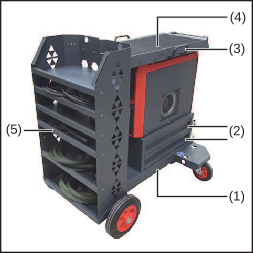
| Item | Designation |
|---|---|
| (1) | Calibration system trolley (option) |
| (2) | Accessory drawers |
| (3) | Cable hanger |
| (4) | Tray |
| (5) | Storage trays |
Calibration system trolley
| Item | Designation |
|---|---|
| (1) | Calibration system trolley (option) |
| (2) | Accessory drawers |
| (3) | Cable hanger |
| (4) | Tray |
| (5) | Storage trays |
Installation
Installing the calibration software
General
NOTE!
Installation of the calibration software was created based on Windows7 and may differ on other operating systems.
1Unzip the software package provided onto your PC:
WT_SW_Fronius_CalibrationSystem2.0_vX.X.XX.X_MULTI.zip
WT_SW_Fronius_CalibrationSystem2.0_vX.X.XX.X_MULTI.zip
Installing the calibration software
General
NOTE!
Installation of the calibration software was created based on Windows7 and may differ on other operating systems.
1Unzip the software package provided onto your PC:
WT_SW_Fronius_CalibrationSystem2.0_vX.X.XX.X_MULTI.zip
WT_SW_Fronius_CalibrationSystem2.0_vX.X.XX.X_MULTI.zip
General
NOTE!
Installation of the calibration software was created based on Windows7 and may differ on other operating systems.
1Unzip the software package provided onto your PC:
WT_SW_Fronius_CalibrationSystem2.0_vX.X.XX.X_MULTI.zip
WT_SW_Fronius_CalibrationSystem2.0_vX.X.XX.X_MULTI.zip
TwinCat
Prerequisite:
The USB cable is not connected.
NOTE!
If a version of TwinCat is already present on your PC (TwinCat 2 or TwinCat 3), installation is not mandatory.
However, Fronius recommends that the version of TwinCat provided is used.
1Open the path:
\WT_SW_Fronius_CalibrationSystem2.0_vX.X.XX.X_MULTI\twincat
\WT_SW_Fronius_CalibrationSystem2.0_vX.X.XX.X_MULTI\twincat
2Install the file located there and follow the setup instructions
3Restart the PC
(only if prompted to do so at the end of installation)
(only if prompted to do so at the end of installation)
USB to LAN driver
(Windows® 7)
NOTE!
The USB to LAN driver is already installed in Windows® 10.
1Connect the PC to the calibration system via USB and switch on the calibration system (green LED lights up)
2Open the Device Manager
If no driver is yet installed, the device will appear as unknown
If no driver is yet installed, the device will appear as unknown
3Install the required driver software from the unzipped software package:
Right click on LAN9500
Right click on LAN9500
4Update driver software
5Find the driver software on the computer
6Open the path:
\WT_SW_Fronius_CalibrationSystem2.0_vX.X.XX.X_MULTI\driver\USBTOLAN\
\WT_SW_Fronius_CalibrationSystem2.0_vX.X.XX.X_MULTI\driver\USBTOLAN\
7Depending on the operating system, select the subfolder (win / win_64) and follow the instructions
After successful installation, the driver can be found under the network adapters: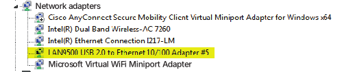
After successful installation, the driver can be found under the network adapters:
8If a driver is already installed,
ensure that it is the latest version and if necessary update it
ensure that it is the latest version and if necessary update it
Also use the connected USB port for future work with the calibration system.
TPS/i SmartCard driver
NOTE!
The TPS/i SmartCard driver is already installed in Windows® 10.
1Open the path:
\WT_SW_Fronius_CalibrationSystem2.0_vX.X.XX.X_MULTI\driver\OMNIKEY\
\WT_SW_Fronius_CalibrationSystem2.0_vX.X.XX.X_MULTI\driver\OMNIKEY\
2 Depending on the operating system, select the subfolder, install the file located there and follow the instructions
Win7 / Win8:
Successful installation will be displayed in the Device Manager as follows:
Win7 / Win8:
Successful installation will be displayed in the Device Manager as follows:
NOTE!
If several SmartCard readers appear in the Device Manager, select the correct one:
1Right-click on the existing SmartCard reader and select "Properties"
Under General / Storage location, a port is specified
e.g..:
Port_#0002.Hub_#0002
This device must be activated!
Under General / Storage location, a port is specified
e.g..:
Port_#0002.Hub_#0002
This device must be activated!
If under Properties / General / Storage location NO port is specified for a SmartCard reader, it must be deactivated:
1Right-click on the affected SmartCard reader and select "Disable Device"
LocalNet FTDI driver
1Connect the power source with LocalNet to the calibration system via USB and switch on both components
2Open the Device Manager
If no driver is yet installed, the device will appear as unknown (USB Serial Port, USB-RS232 cable, etc.)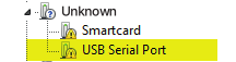
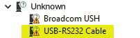
If no driver is yet installed, the device will appear as unknown (USB Serial Port, USB-RS232 cable, etc.)
3Install the required driver software from the unzipped software package:
Right click on USB Serial Port
Right click on USB Serial Port
4Update driver software
5Find the driver software on the computer
6Open the path:
\WT_SW_Fronius_CalibrationSystem2.0_vX.X.XX.X_MULTI\driver\FTDI\
\WT_SW_Fronius_CalibrationSystem2.0_vX.X.XX.X_MULTI\driver\FTDI\
7Confirm and follow the instructions
After successful installation of the driver, the COM Port can be found under Ports:
After successful installation of the driver, the COM Port can be found under Ports:
8Restart the PC
(only if prompted to do so at the end of installation)
(only if prompted to do so at the end of installation)
9If a driver is already installed,
ensure that it is the latest version and if necessary update it
ensure that it is the latest version and if necessary update it
If the device still appears as unknown after installation, repeat the process.
Desktop software installation
Requirements:
- Windows 7 or higher
- Local admin rights
- Screen resolution higher than 1024 * 768
- .net Framework 4.7.2
If this .net Framework version is not yet installed on the computer, a message is displayed to this effect.
The appropriate .net Framework version can be downloaded and installed from the following link:
https://dotnet.microsoft.com/download/dotnet-framework-runtime/net472
1Open the path:
\WT_SW_Fronius_CalibrationSystem2.0_vX.X.XX.X_MULTI\application
\WT_SW_Fronius_CalibrationSystem2.0_vX.X.XX.X_MULTI\application
2Install the file located there and follow the setup instructions
Changing network settings
1Setting network settings
- via the calibration software:

or - under the network settings (TCP/IPv4) of the adapter:
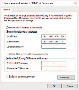
Changing the network settings for USB calibration
IMPORTANT! Prerequisites for USB calibration:
- DHCP server, which starts automatically when the program starts.
- .net Framework, at least version 4.7.2
1Specify network settings for USB calibration
- Via the calibration software:
Settings / Configure network adapter / SpeedNet / Ethernet ...
or - From the network settings (TCP/IPv4) of the adapter:
Use the following IP address: 192.168.125.200
2Check if the IP address 192.168.125.1 is displayed on the power source
Action if the IP address 192.168.125.1 is not displayed on the power source:
- Check if the DHCP server is running (icon!)
If the DHCP server is not running, restart the software. - Disconnect the USB briefly from the power source and reconnect it again
- Only connect the USB Ethernet adapter to the calibration system, not to the computer/laptop
Setting a TwinCat route
1Click on the TwinCat symbol in the lower bar of your PC and select "Edit routes"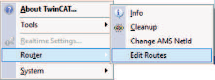
2Add a new route by going to "Add" and then "Broadcast Search"
The calibration system is then normally displayed.
The calibration system is then normally displayed.
3Implement the following settings: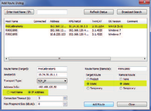
4Deactivate "Encrypt password (Twincat 3 only)" 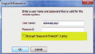 If connection is successful, an X is displayed in the overview.
5Close the window by clicking "Close"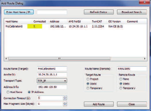
Possible errors/points to check if the route cannot be set as described above include:
- Check network settings:
The calibration station must be accessible in the Windows command prompt (CMD) at the IP address 192.168.120.50 with the ping command. - Various security programmes (e.g. F-Secure, etc.) may block the network connection.
If necessary, allow network traffic - Reset the calibration station and ensure that the green LED is on
- Remove the USB cable for a short time, then reconnect it and try again
- Restart the PC
Setting the language, system information
Setting the language

After the calibration software has been installed, the language can be set for the user interface:
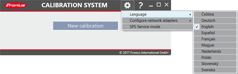
The system switches to the chosen language when the program is restarted.
NOTE!
Only the user interface of the calibration software is displayed in the chosen language. The language for the calibration report must be set separately!
Setting the language
After the calibration software has been installed, the language can be set for the user interface:
The system switches to the chosen language when the program is restarted.
NOTE!
Only the user interface of the calibration software is displayed in the chosen language. The language for the calibration report must be set separately!
Retrieving system information
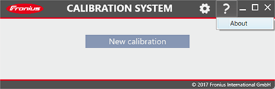
Clicking on the ? displays the following system information:
- Software version of the calibration software installed
- Software version of the Beckhoff elements installed in the calibration system
Fitting the system components
Connecting the power source and calibration system
NOTE!
The system structure varies depending on the welding system to be calibrated.
The following work steps apply to all welding systems.
Details of the respective system structure are provided with the individual welding systems.
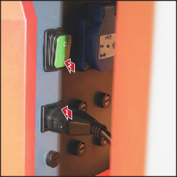
1Plug the mains cable into the calibration system
2Switch on the mains switch
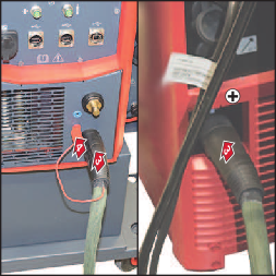
3Connect the (+) power cable to the calibration system and the power source
4Connect the sense lead (red) to the calibration system
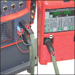
5Connect the (-) power cable to the calibration system and the power source
6Connect the sense lead (blue) to the calibration system
7Connect the control cable (SpeedNet, LocalNet, USB, Tuchel, etc.) to the calibration system and to the welding system
8Switch on the power source
9Start calibration
Connecting the power source and calibration system
NOTE!
The system structure varies depending on the welding system to be calibrated.
The following work steps apply to all welding systems.
Details of the respective system structure are provided with the individual welding systems.
1Plug the mains cable into the calibration system
2Switch on the mains switch
3Connect the (+) power cable to the calibration system and the power source
4Connect the sense lead (red) to the calibration system
5Connect the (-) power cable to the calibration system and the power source
6Connect the sense lead (blue) to the calibration system
7Connect the control cable (SpeedNet, LocalNet, USB, Tuchel, etc.) to the calibration system and to the welding system
8Switch on the power source
9Start calibration
Connecting the welding wire calibration system
NOTE!
The power cables are not relevant for calibration of the welding wire!
Establish data communication between the following:
power source and calibration system (LocalNet, SpeedNet, USB, etc.)
power source and wirefeeder (LocalNet, SpeedNet, USB, etc.)
welding wire calibration system and calibration system
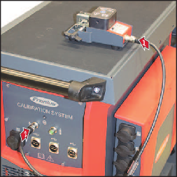
1Connect the connection cable to the welding wire calibration system
IMPORTANT! A maximum of 3 connection cables (max. 15 m) can be used to connect the welding wire calibration system and the calibration system!
IMPORTANT! A maximum of 3 connection cables (max. 15 m) can be used to connect the welding wire calibration system and the calibration system!
2Connect the connection cable to the calibration system
3Disconnect the (+) power cable of the calibration system from the welding system
4Connect the MIG/MAG welding torch to the welding system
5Remove the gas nozzle from the welding torch
6Thread the wire
The welding wire should protrude approx. 200 mm from the contact tip.
The welding wire should protrude approx. 200 mm from the contact tip.
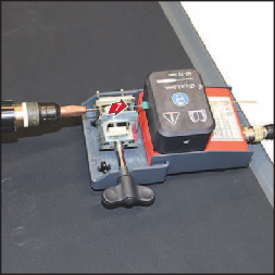
7Thread the welding wire into the intake part of the sensor
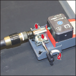
8Secure the welding torch in the welding wire calibration system at the contact tip
9Make sure that the torch hosepack is arranged as straight as possible
The system is now ready for welding wire calibration.
NOTE!
When calibrating robot welding systems, the welding wire calibration system is usually attached to the contact tip of the robot welding torch.
If, in this case, it is not possible to attach it properly, the following longer contact tips may be used on the robot welding torch:
- 42,0001,0056
contact tip 1.6/M6/ø8x33 mm - 42,0001,3485
contact tip 1.6/M8/ø8x35 mm/CB4.8 - 42,0001,5413
contact tip 3.2/M10/ø10x40 mm
Connecting the computer to the calibration system and signature pad
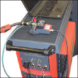
1Connect the USB connection cable to the calibration system and the computer / laptop
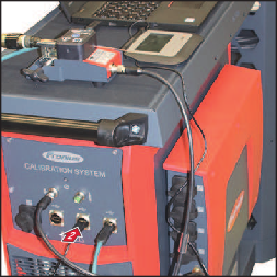
2Connect the Signotec signature pad to the calibration system
Connecting the gas supply with interface calibration system, calibration system and power source
IMPORTANT! The interface calibration system is required for calibrating a gas supply.
NOTE!
The power cables are not relevant for calibration of a gas supply!
Ensure the following data communications and connections:
The gas supply is connected to the interface calibration system by means of a gas hose.
The calibration system and the interface calibration system are connected to each other.
Power source/wirefeeder are connected to the interface calibration system by means of a gas hose.
The power source and calibration system are connected to each other (e.g. via LocalNet, SpeedNet, etc.)
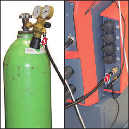
1Connect the gas hose:
to the gas pressure regulator
and
to the Gas IN connection on the calibration system interface
max. inlet pressure: 5 bar
to the gas pressure regulator
and
to the Gas IN connection on the calibration system interface
max. inlet pressure: 5 bar
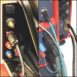
2Connect the gas hose:
to the wirefeeder or the power source
and
to the Gas OUT connection on the interface calibration system
to the wirefeeder or the power source
and
to the Gas OUT connection on the interface calibration system
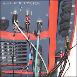
3Connect the gas connection on the calibration system with the data connection on the calibration system interface
4Connect the power source with the calibration system
Calibrating welding systems
General information
Mains voltage measurement for single-phase power sources
With single-phase machines, the mains voltage must be measured manually using a FLUKE measuring device.
1Enter the measured mains voltage in the box
2[ ] Enable In Use
3Under external measuring equipment, enter the FLUKE measuring device used
General information
Mains voltage measurement for single-phase power sources
With single-phase machines, the mains voltage must be measured manually using a FLUKE measuring device.
1Enter the measured mains voltage in the box
2[ ] Enable In Use
3Under external measuring equipment, enter the FLUKE measuring device used
Mains voltage measurement for single-phase power sources
With single-phase machines, the mains voltage must be measured manually using a FLUKE measuring device.
1Enter the measured mains voltage in the box
2[ ] Enable In Use
3Under external measuring equipment, enter the FLUKE measuring device used
Correcting set values and load resistances
If the values specified by the calibration software are not achieved, the set value or load resistance may need to be modified.
Examples:
AccuPocket 150 / 400 Tig
Current calibration (M1: Set value [A] = 60 A / RLoad [mOhm] = 240 mOhm)
TransTig 2200 Job
Current calibration (M5: RLoad [mOhm] = 96 mOhm)
VarioSynergic 3400
Read the measured value for the respective level in the calibration program and enter it in the "set value" box.
The calibration software - calibrating welding systems in general
The calibration software - calibrating welding systems in general
IMPORTANT! Before starting the calibration process:
- The power source must be connected to the calibration system.
- Calibration of a wirefeeder takes place after calibration of the power source.
- The power source to be calibrated must be switched on at least 5 minutes before the calibration process starts.
The calibration process is started from the calibration software on the computer / laptop.
1Start the calibration program
2Click [New calibration]
The preliminary settings / contractor data are displayed.
The preliminary settings / contractor data are displayed.
3Enter the details for a new contractor (= Person performing calibration):
- Name
- Address
- Postcode
- Calibration technician
4Click on [Add]
or
select current contractor from the list shown
or
select current contractor from the list shown
5Enter the serial numbers of the measuring equipment:
- Calibration system
- Welding wire calibration system
- Gas calibration system
6Click [Next >]
The preliminary settings / customer data are displayed.
The preliminary settings / customer data are displayed.
7Enter the details for a new client:
- Name
- Address
- Postcode
- Customer number
8Click on [Add]
or
select current client from the list shown
Under Others, inventory numbers, order numbers and observations can be entered.
or
select current client from the list shown
Under Others, inventory numbers, order numbers and observations can be entered.
9Click [Next >]
The preliminary settings / device selection are displayed.
The preliminary settings / device selection are displayed.
10Under Settings, select the connection to the power source:
o LocalNet
o SpeedNet
o Fronius devices
o Manual
o LocalNet
o SpeedNet
o Fronius devices
o Manual
11Device type and brand
12Click on [Establish connection]
If the connection is established successfully, a message to this effect is displayed and the data from the power source and wirefeeder is automatically read in.
Welding current, welding voltage and wire speed are pre-selected. To deselect them, click on the respective check box.
If a gas flow calibration is to be performed, click on the check box.
If the connection is established successfully, a message to this effect is displayed and the data from the power source and wirefeeder is automatically read in.
Welding current, welding voltage and wire speed are pre-selected. To deselect them, click on the respective check box.
If a gas flow calibration is to be performed, click on the check box.
13Click [Next >]
The preliminary settings / calibration parameters are displayed:
five measured values M1 - M5 for each power source and wirefeeder
The preliminary settings / calibration parameters are displayed:
five measured values M1 - M5 for each power source and wirefeeder
- Welding current [A]
- Welding voltage [V]
- Wire speed
14Click [Next >]
The preliminary settings / general measurement data are displayed:
The preliminary settings / general measurement data are displayed:
- Ambient temperature [° C]
- Mains voltage [V]
- Open circuit voltage US [V]
15Carry out a visual inspection of the welding system and the calibration system, according to the calibration instructions
16If the visual inspection does not reveal any defects, select [Click here]
17Click [Next >]
The summary of the calibration process is displayed.
The summary of the calibration process is displayed.
18Set calibration class:
o Standard
o Precision
For details on calibration class, see page (→).
o Standard
o Precision
For details on calibration class, see page (→).
19Click [Start automatic calibration process]
The calibration process starts.
When a calibration process is active
The calibration process starts.
When a calibration process is active
- A corresponding notification is displayed
- The [Interrupt calibration] button is available
- All measuring points are checked one after the other
- Current measured values are displayed
- A progress bar with the remaining time is displayed
20Change over the welding system for calibration of the welding wire:
(see page (→) onwards)
(see page (→) onwards)
- Connect welding wire calibration system and calibration system
- Disconnect (+) power cable from welding system
- Connect the welding torch to the welding system
- Remove the gas nozzle from the welding torch
- Thread the wire
- Thread the welding wire into the sensor
- Secure the welding torch in the welding wire calibration system
CAUTION!
Danger from welding wire emerging at speed.
This can result in personal injury.
Keep head and body away from the welding wire calibration system.
Wear suitable protective goggles.
Make sure that when the welding wire emerges, it does not touch any electrically conducting, earthed or live parts.
Make sure that there is sufficient space for the emerging welding wire (approx. 10 m).
Make sure that no one is endangered by the emerging welding wire.
21Click on [OK] to start calibration of the wirefeeder systemWhen the calibration process is complete, a corresponding notification is displayed and the [Print calibration report] button is available.
22Click [Print calibration report]
Calibration system / create report is displayed.
Calibration system / create report is displayed.
23Enter the details to create the calibration report:
Under Template, select the language for the calibration report from the list
Enter the output path
Enter or search for ( [Browse] ) the file name
If the Signotec signature pad is connected and has been detected by the calibration system, a notification to this effect is displayed under Signature pad.
If not, check the connection of the Signotec signature pad to the calibration system and then click on [Reconnect].
Under Template, select the language for the calibration report from the list
Enter the output path
Enter or search for ( [Browse] ) the file name
If the Signotec signature pad is connected and has been detected by the calibration system, a notification to this effect is displayed under Signature pad.
If not, check the connection of the Signotec signature pad to the calibration system and then click on [Reconnect].
24Sign the Signotec signature pad with the corresponding digital pen
25Press [OK] on the Signotec signature pad
The signature is sent to the calibration software.
x ... Cancel signature
Refresh ... new signature
A corresponding notification is displayed after the signature has been received successfully.
The signature is sent to the calibration software.
x ... Cancel signature
Refresh ... new signature
A corresponding notification is displayed after the signature has been received successfully.
26Click [Create PDF]
IMPORTANT! Only after the confirmation "PDF created successfully!" is displayed, will the calibration report be saved.
IMPORTANT! Only after the confirmation "PDF created successfully!" is displayed, will the calibration report be saved.
The calibration software - calibrating welding systems in general
IMPORTANT! Before starting the calibration process:
- The power source must be connected to the calibration system.
- Calibration of a wirefeeder takes place after calibration of the power source.
- The power source to be calibrated must be switched on at least 5 minutes before the calibration process starts.
The calibration process is started from the calibration software on the computer / laptop.
1Start the calibration program
2Click [New calibration]
The preliminary settings / contractor data are displayed.
The preliminary settings / contractor data are displayed.
3Enter the details for a new contractor (= Person performing calibration):
- Name
- Address
- Postcode
- Calibration technician
4Click on [Add]
or
select current contractor from the list shown
or
select current contractor from the list shown
5Enter the serial numbers of the measuring equipment:
- Calibration system
- Welding wire calibration system
- Gas calibration system
6Click [Next >]
The preliminary settings / customer data are displayed.
The preliminary settings / customer data are displayed.
7Enter the details for a new client:
- Name
- Address
- Postcode
- Customer number
8Click on [Add]
or
select current client from the list shown
Under Others, inventory numbers, order numbers and observations can be entered.
or
select current client from the list shown
Under Others, inventory numbers, order numbers and observations can be entered.
9Click [Next >]
The preliminary settings / device selection are displayed.
The preliminary settings / device selection are displayed.
10Under Settings, select the connection to the power source:
o LocalNet
o SpeedNet
o Fronius devices
o Manual
o LocalNet
o SpeedNet
o Fronius devices
o Manual
11Device type and brand
12Click on [Establish connection]
If the connection is established successfully, a message to this effect is displayed and the data from the power source and wirefeeder is automatically read in.
Welding current, welding voltage and wire speed are pre-selected. To deselect them, click on the respective check box.
If a gas flow calibration is to be performed, click on the check box.
If the connection is established successfully, a message to this effect is displayed and the data from the power source and wirefeeder is automatically read in.
Welding current, welding voltage and wire speed are pre-selected. To deselect them, click on the respective check box.
If a gas flow calibration is to be performed, click on the check box.
13Click [Next >]
The preliminary settings / calibration parameters are displayed:
five measured values M1 - M5 for each power source and wirefeeder
The preliminary settings / calibration parameters are displayed:
five measured values M1 - M5 for each power source and wirefeeder
- Welding current [A]
- Welding voltage [V]
- Wire speed
14Click [Next >]
The preliminary settings / general measurement data are displayed:
The preliminary settings / general measurement data are displayed:
- Ambient temperature [° C]
- Mains voltage [V]
- Open circuit voltage US [V]
15Carry out a visual inspection of the welding system and the calibration system, according to the calibration instructions
16If the visual inspection does not reveal any defects, select [Click here]
17Click [Next >]
The summary of the calibration process is displayed.
The summary of the calibration process is displayed.
18Set calibration class:
o Standard
o Precision
For details on calibration class, see page (→).
o Standard
o Precision
For details on calibration class, see page (→).
19Click [Start automatic calibration process]
The calibration process starts.
When a calibration process is active
The calibration process starts.
When a calibration process is active
- A corresponding notification is displayed
- The [Interrupt calibration] button is available
- All measuring points are checked one after the other
- Current measured values are displayed
- A progress bar with the remaining time is displayed
20Change over the welding system for calibration of the welding wire:
(see page (→) onwards)
(see page (→) onwards)
- Connect welding wire calibration system and calibration system
- Disconnect (+) power cable from welding system
- Connect the welding torch to the welding system
- Remove the gas nozzle from the welding torch
- Thread the wire
- Thread the welding wire into the sensor
- Secure the welding torch in the welding wire calibration system
CAUTION!
Danger from welding wire emerging at speed.
This can result in personal injury.
Keep head and body away from the welding wire calibration system.
Wear suitable protective goggles.
Make sure that when the welding wire emerges, it does not touch any electrically conducting, earthed or live parts.
Make sure that there is sufficient space for the emerging welding wire (approx. 10 m).
Make sure that no one is endangered by the emerging welding wire.
21Click on [OK] to start calibration of the wirefeeder systemWhen the calibration process is complete, a corresponding notification is displayed and the [Print calibration report] button is available.
22Click [Print calibration report]
Calibration system / create report is displayed.
Calibration system / create report is displayed.
23Enter the details to create the calibration report:
Under Template, select the language for the calibration report from the list
Enter the output path
Enter or search for ( [Browse] ) the file name
If the Signotec signature pad is connected and has been detected by the calibration system, a notification to this effect is displayed under Signature pad.
If not, check the connection of the Signotec signature pad to the calibration system and then click on [Reconnect].
Under Template, select the language for the calibration report from the list
Enter the output path
Enter or search for ( [Browse] ) the file name
If the Signotec signature pad is connected and has been detected by the calibration system, a notification to this effect is displayed under Signature pad.
If not, check the connection of the Signotec signature pad to the calibration system and then click on [Reconnect].
24Sign the Signotec signature pad with the corresponding digital pen
25Press [OK] on the Signotec signature pad
The signature is sent to the calibration software.
x ... Cancel signature
Refresh ... new signature
A corresponding notification is displayed after the signature has been received successfully.
The signature is sent to the calibration software.
x ... Cancel signature
Refresh ... new signature
A corresponding notification is displayed after the signature has been received successfully.
26Click [Create PDF]
IMPORTANT! Only after the confirmation "PDF created successfully!" is displayed, will the calibration report be saved.
IMPORTANT! Only after the confirmation "PDF created successfully!" is displayed, will the calibration report be saved.
Calibrating welding systems with LocalNet (TPS, TSt, MW, TT)
Overview - LocalNet
Welding systems with external wirefeeder
- TS 4000 / 5000
- TPS 3200 / 4000 / 5000
- TIME 5000 Digital
- CMT 4000 Advanced
- TSt 3500/5000
- TSt 3500 / 5000 Rob
- TSt 3500 / 5000 Syn
- TSt 4000 / 5000 Pulse
Welding systems with integrated wire drive
- TPS 2700
- TSt 2200c (cable harness 43,0004,4850 also required)
- TSt 2500c / 2700c / 3000 c Pulse / 3500c
TIG welding systems
- TT 800 / 2200 / 2500 / 3000 / 4000 / 5000
- TT 800 / 2200 / 2500 / 3000 / 4000 / 5000 Job
- TT 2200 / 2500 / 3000 / 4000 / 5000 Comfort
- MW 1700 / 2200 / 2500 / 3000 / 4000 / 5000
- MW 1700 / 2200 / 2500 / 3000 / 4000 / 5000 Job
- MW 2200 / 2500 / 3000 / 4000 / 5000 Comfort
Manual metal arc welding systems
- TP 4000 / 5000 CEL
The power sources listed above have a LocalNet port and are calibrated using the following calibration process.
Overview - LocalNet
Welding systems with external wirefeeder
- TS 4000 / 5000
- TPS 3200 / 4000 / 5000
- TIME 5000 Digital
- CMT 4000 Advanced
- TSt 3500/5000
- TSt 3500 / 5000 Rob
- TSt 3500 / 5000 Syn
- TSt 4000 / 5000 Pulse
Welding systems with integrated wire drive
- TPS 2700
- TSt 2200c (cable harness 43,0004,4850 also required)
- TSt 2500c / 2700c / 3000 c Pulse / 3500c
TIG welding systems
- TT 800 / 2200 / 2500 / 3000 / 4000 / 5000
- TT 800 / 2200 / 2500 / 3000 / 4000 / 5000 Job
- TT 2200 / 2500 / 3000 / 4000 / 5000 Comfort
- MW 1700 / 2200 / 2500 / 3000 / 4000 / 5000
- MW 1700 / 2200 / 2500 / 3000 / 4000 / 5000 Job
- MW 2200 / 2500 / 3000 / 4000 / 5000 Comfort
Manual metal arc welding systems
- TP 4000 / 5000 CEL
The power sources listed above have a LocalNet port and are calibrated using the following calibration process.
System layout
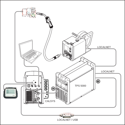
Example layout with TPS 5000: CALSYS = Calibration system, CON = Interconnecting hosepack
Connecting the power source and calibration system
1Plug the mains cable into the calibration system
2Switch on the mains switch
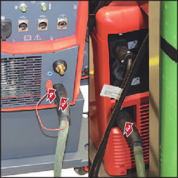
3Connect the (+) power cable to the calibration system and the power source
4Connect the sense lead (red) to the calibration system
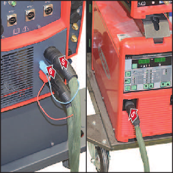
5Connect the (-) power cable to the calibration system and the power source
6Connect the sense lead (blue) to the calibration system
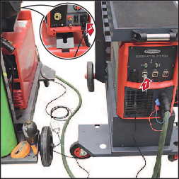
7Connect the LocalNet/USB converter to the calibration system and to a free LocalNet port on the welding system If there is no LocalNet port available, use the LocalNet passive distributor (4,100,261) e.g. for TSt 5000
8Switch on the power source
9Start calibration
For TransSteel TSt 2200c only:
A cable harness (item number 43,0004,4850) is also required when calibrating a TSt 2200c power source.
The calibration process is performed with an open power source housing.
WARNING!
Danger from electric current.
This can result in serious personal injury and damage to property.
Before starting work, switch off all the devices and components involved and disconnect them from the grid.
Secure all the devices and components involved to prevent unintentional restarting.
After opening the device, use a suitable measuring instrument to check that electrically charged components (such as capacitors) have been discharged.
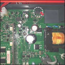
7Connect the LocalNet/USB converter to the calibration system
8Remove the right side panel from the power source
9Connect the cable harness 43,0004,4850 to the 6-pin connector on the PC board LSTMAG20 as shown in the illustration
10Connect the cable harness and LocalNet/USB converter
WARNING!
Danger from electric current - the calibration process takes place with the housing open.
This can result in serious personal injury and damage to property.
After switching on the power source, do not touch the parts inside the housing!
Use only suitable measuring or test probes to touch parts inside the device!
Keep people away from the open power source when carrying out the calibration!
11Connect the power source to the grid and switch it on
12Start calibration
Information on the calibration procedure
Preliminary settings / device selection:Under Settings, select the connection to the power source:
o LocalNet
Set calibration class:
o Precision
o Standard
For details on calibration class, see page (→).
Calibrating welding systems with SpeedNet (TPS /i, iWave 300i - 500i)
Overview - SpeedNet
MIG/MAG welding systems with external wirefeeder
- TPS 320i / 400i / 500i / 600i
- TPS 400i LSC ADV
MIG/MAG welding systems with integrated wire drive
- TPS 270i C
- TPS 320i C
TIG welding systems
- iWave 300i - 500 DC
- iWave 300i - 500i AC/DC
The power sources listed above have a SpeedNet port and are calibrated using the following calibration process.
Overview - SpeedNet
MIG/MAG welding systems with external wirefeeder
- TPS 320i / 400i / 500i / 600i
- TPS 400i LSC ADV
MIG/MAG welding systems with integrated wire drive
- TPS 270i C
- TPS 320i C
TIG welding systems
- iWave 300i - 500 DC
- iWave 300i - 500i AC/DC
The power sources listed above have a SpeedNet port and are calibrated using the following calibration process.
System layout
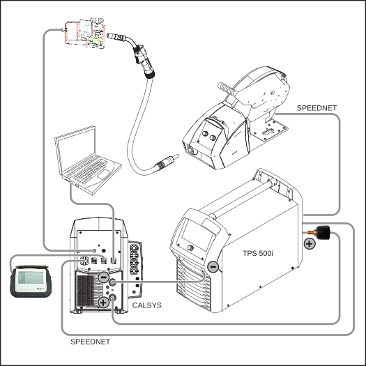
Example layout with TPS 500i: CALSYS = Calibration System
Connecting the power source and calibration system
1Plug the mains cable into the calibration system
2Plug the mains cable into the grid
3Switch on the mains switch
NOTE!
If there is a power connector for the high current socket on the power source, use the adapter for the high current sockets to bayonet (42,0001,4482).
4Connect the (+) power cable to the calibration system and the power source
5Connect the sense lead (red) to the calibration system
6Connect the (-) power cable to the calibration system and the power source
7Connect the sense lead (blue) to the calibration system
8Switch on the power source
9Connect the SpeedNet cable to the calibration system and to a free SpeedNet connection socket on the welding system
Information on the calibration procedure
Preliminary settings / device selection:
Under Settings, select the connection to the power source:
o SpeedNet
Define the calibration class:
o Precision
Calibrating welding systems with USB / SpeedNet
Overview - USB
Software version 1.0.28 and higher:
TIG welding systems
- iWave 230i DC
- iWave 190i / 230i AC/DC
MIG/MAG welding systems with external wirefeeder
- TPS 320i / 400i / 500i / 600i
- TPS 400i LSC ADV
MIG/MAG welding systems with integrated wire drive
- TPS 270i C
- TPS 320i C
The TPS /i power sources can be calibrated via both the SpeedNet port and the USB port.
The power sources listed above have a USB port and are calibrated using the following calibration process.
Overview - USB
Software version 1.0.28 and higher:
TIG welding systems
- iWave 230i DC
- iWave 190i / 230i AC/DC
MIG/MAG welding systems with external wirefeeder
- TPS 320i / 400i / 500i / 600i
- TPS 400i LSC ADV
MIG/MAG welding systems with integrated wire drive
- TPS 270i C
- TPS 320i C
The TPS /i power sources can be calibrated via both the SpeedNet port and the USB port.
The power sources listed above have a USB port and are calibrated using the following calibration process.
System layout
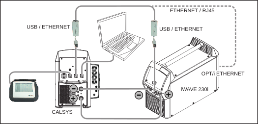
Example layout with iWave 230i: CALSYS = Calibration System
Connecting the power source and calibration system
Also required:
- 2 USB Ethernet adapters (from the scope of delivery of the calibration system)
If the OPT/i Ethernet option is available at the power source, only one USB Ethernet adapter is required. - 1 Ethernet cable with RJ45 plug connectors
1Plug the mains cable into the calibration system
2Plug the mains cable into the grid
3Switch on the mains switch
NOTE!
If there is a power connector for the high current socket on the power source, use the adapter for the high current sockets to bayonet (42,0001,4482).
4Connect the (+) power cable to the calibration system and the power source
5Connect the sense lead (red) to the calibration system
6Connect the (-) power cable to the calibration system and the power source
7Connect the sense lead (blue) to the calibration system
8Switch on the power source
9Only when calibrating iWave 230i DC and iWave 190i / 230i AC/DC:
In the power source setup menu under Ignition and mode settings, set the HF ignition parameter to "off".
In the power source setup menu under Ignition and mode settings, set the HF ignition parameter to "off".
10Connect the USB Ethernet adapter to the calibration system
11Connect the USB Ethernet adapter to the USB port of the welding system
12Connect the USB Ethernet adapter using the Ethernet cable
Information on the calibration procedure
IMPORTANT! Before starting the calibration process, check / set the network settings for USB calibration (see page (→)).
Preliminary settings / device selection:
Under Settings, select the connection to the power source:
o SpeedNet
[ ] Activate USB
When the connection has been successfully established, a message to this effect is displayed.
What to do if connection is unsuccessful:
- Check if the DHCP server is running (icon in the task bar!)
If the DHCP server is not running, restart the software and check the network settings. - Disconnect the USB briefly from the power source and reconnect it again
Define the calibration class:
o Precision
Calibrating other Fronius welding systems
Overview - other Fronius devices
MIG/MAG welding systems with external wirefeeder
- VarioSynergic 3400 / 4000 / 5000
MIG/MAG welding systems with integrated wire drive
- VarioStar 1500 / 2500 / 3100
- VarioSynergic 3400 / 4000 / 5000
TIG welding systems
- MagicWave 2600 / 2600 CEL / 3000
- TransTig 2600 / 2600 CEL / 3000
- TransTig 1750 Puls
- TransTig 170 / 210
Manual metal arc welding systems
- TransPocket 125 VRD / 150 / 180
- TransPocket 1100 / 1200 / 1400 / 1500 / 2000
- TransPocket 2500 / 3500 - RC, TIG, Comfort
- AccuPocket 150
The Fronius power sources listed above do not have a SpeedNet or LocalNet port and are calibrated using the following calibration process.
Overview - other Fronius devices
MIG/MAG welding systems with external wirefeeder
- VarioSynergic 3400 / 4000 / 5000
MIG/MAG welding systems with integrated wire drive
- VarioStar 1500 / 2500 / 3100
- VarioSynergic 3400 / 4000 / 5000
TIG welding systems
- MagicWave 2600 / 2600 CEL / 3000
- TransTig 2600 / 2600 CEL / 3000
- TransTig 1750 Puls
- TransTig 170 / 210
Manual metal arc welding systems
- TransPocket 125 VRD / 150 / 180
- TransPocket 1100 / 1200 / 1400 / 1500 / 2000
- TransPocket 2500 / 3500 - RC, TIG, Comfort
- AccuPocket 150
The Fronius power sources listed above do not have a SpeedNet or LocalNet port and are calibrated using the following calibration process.
System layout
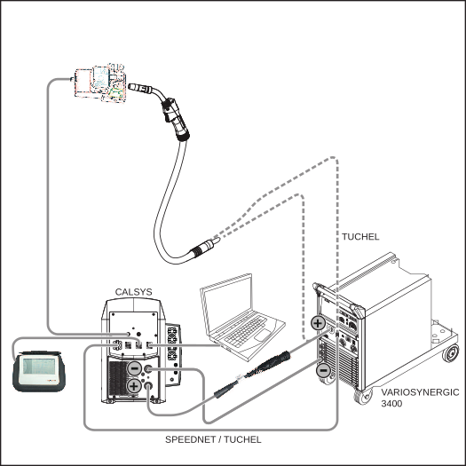
Example layout with VarioSynergic 3400: CALSYS = Calibration System
Connecting the power source and calibration system
1Plug the mains cable into the calibration system
2Plug the mains cable into the grid
3Switch on the mains switch
NOTE!
Use the corresponding adapters depending on the size of the current sockets on the power source.
4Connect the (+) power cable to calibration system
5Connect the (+) power cable to the power source (e.g. using the Fronius/central connector adapter, as shown in the setup example)
6Connect the sense lead (red) to the calibration system
7Connect the (-) power cable to the calibration system and the power source
8Connect the sense lead (blue) to the calibration system
If there is a Tuchel connection on the power source:
9Connect the Tuchel adapter cable to the power source and to the calibration system
10Switch on the power source
Calibrating the wire:
11Disconnect the (+) power cable and adapter from the power source
12Disconnect the Tuchel adapter cable from the power source
13Connect the welding torch to the power source
14Connect the Tuchel cable from the welding torch to the power source
15Connect the welding wire calibration system (see page (→))
Information on the calibration procedure for TransPocket welding systems
Set the manual metal arc welding operating mode on the power source and start the calibration program.
Preliminary settings / device selection:
Under settings, select:
o Fronius devices
Select the respective TransPocket variant
IMPORTANT! The mains voltage displayed is incorrect!
With single-phase machines, the mains voltage must be measured manually using a FLUKE measuring device, and entered!
[ ] Enable In Use and enter the measuring device used under External measuring equipment
Set calibration class:
o Precision
o Standard
For details on calibration class, see page (→).
- Set the specified measured value M1 on the power source and start the measuring process
- Enter the value displayed on the power source in the Display [A] box and click [Next >]
- Repeat the steps for the measured values M2 - M5 - M1
(10 measurements)
Information on the calibration procedure of the TransTig 1750 Puls
Connect the Tuchel adapter cable to the power source and to the calibration system
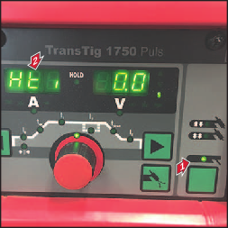
Set the welding current on the power source:
- Set the manual metal arc welding operating mode
- Set the parameter Hti = 0 in the MMA welding setup menu
Start the calibration program
Preliminary settings / device selection
Under settings, select:
o Fronius devices
Select TransTig 1750 Puls
Click [External start with calibration system]
Enter the serial number of the TT 1750 Puls in the box
IMPORTANT! The mains voltage displayed is incorrect!
With single-phase machines, the mains voltage must be measured manually using a FLUKE measuring device, and entered!
[ ] Enable In Use and enter the measuring device used under External measuring equipment
Define the calibration class:
o Precision
- Set the specified measured value M1 on the power source and start the measuring process
- Enter the value displayed on the power source in the Display [A] box and click [Next >]
- Repeat the steps for the measured values M2 - M5 - M1 (10 measurements)
Information on the calibration procedure of the VarioSynergic 3400
Open the clamping lever on the wirefeeder
Thread the welding wire back again and attach to the wire spool
Connect the Tuchel adapter cable to the power source and to the calibration system
Start the calibration program
Preliminary settings / device selection:
Under settings, select:
o Fronius devices
Select VarioSynergic 3400
[Display available] and [External start with calibration system] have been pre-selected
Enter the serial number of the VarioSynergic in the field
For the wirefeeder, enter five wire speed measured values M1 - M5 [m/min]:
- The measured value M5 corresponds to the maximum wire speed value (= 18 m/min with VS 3400).
- Enter the remaining measured values by pressing the tab key
Specify the following settings on the power source:
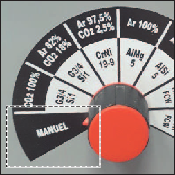
Move the welding program selector switch to the MANUAL position
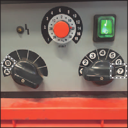
For the US measurement, set the coarse stage switch to B and the fine stage switch to 7
Set the toggle switch to A (current)
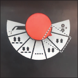
Set the selector switch on the interior of the device to 2-step mode.
Starting the measuring process
Define the calibration class:
o Precision
o Standard
NOTE!
In the case of step-switched machines, the set values can be adapted manually in the calibration program.
- Set the stage switch on the power source as specified in the calibration program for measuring point M1 (e.g. stage A1)
- Start the calibration process
- Read the measured value for the respective level in the calibration program and enter it in the Set value [A] box
- Start the calibration process
- Enter the value displayed on the power source in the Display [A] box and click [Next >]
- Repeat steps for measuring points M2 - M5
For the subsequent measurement of M5 to M1, the set values entered are saved by the calibration program. - Repeat the steps for the welding voltage
After completing the current and voltage calibration, the message [Start calibration wirefeeder 1!] is displayed.
To calibrate the welding wire on the power source, specify the following settings:
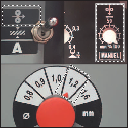
Set the toggle switch to wirefeeder.
Set the wirefeeder controller on the interior of the device under MANUAL to 100 %.
Set the wire diameter for the welding wire used.
Set the wirefeeder controller on the interior of the device under MANUAL to 100 %.
Set the wire diameter for the welding wire used.
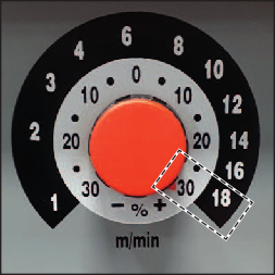
Depending on the measurement, set the wire speed controller to the relevant measured value according to the table.
- Disconnect the +/- current cables from the calibration station on the power source
- Connect the welding torch and Tuchel plug to the power source
- Remove the gas nozzle
- Thread the wire
- Close the clamping lever on the wirefeeder
- Thread the wire until it protrudes approx. 200 mm from the contact tip
- Thread the welding wire into the intake part of the sensor
- Use clamps to secure the welding torch in the welding wire calibration system at the contact tip
- Click on [Start calibration wirefeeder 1!]
- Set the respective measured value on the power source wire speed controller. (e.g.: M1 = 1 m)
CAUTION!
Danger from welding wire emerging at speed.
This can result in personal injury.
Keep head and body away from the welding wire calibration system.
Wear suitable protective goggles.
Make sure that when the welding wire emerges, it does not touch any electrically conducting, earthed or live parts.
Make sure that there is sufficient space for the emerging welding wire (approx. 10 m).
Make sure that no one is endangered by the emerging welding wire.
- Press and hold the torch trigger to start the wirefeeder
- After about 3 seconds of wirefeeder running time, click on "Start measuring process" in the calibration program and release the torch trigger
- Enter the value displayed on the power source under "Display" and click on [Next >]
- Repeat the steps for the measurements from M2 to M5 and M1
Information on the calibration procedure of the TransTig 170 / 210
Requirement:
- TransTig 170 / 210 firmware version: at least 4.1.7 or higher
- Start with external ignition aid (EHF) activated:
TIG setup menu - Level 2 / IGn / EHF
After calibration, deactivate EHF again or reset it to the original value. - Break voltage UCo set to a value > 30 V:
TIG setup menu - Level 2 / UCo > 30 V (factory setting = 35 V)
Notes on voltage calibration:
- The maximum voltage during calibration is 30 V.
- The same resistance of 480 mOhm is used for all measuring points.
- The calibration software automatically specifies the measuring points to be measured.
- The voltage is regulated by the current;
the predefined current values are standard values and may have to be adjusted to achieve the specified voltages.
Recommended points for calibration:
Voltage [V] | Resistance [mOhm] | Current on the device [A] |
|---|---|---|
10 | 480 | 20 |
15 | 480 | 29 |
20 | 480 | 39 |
25 | 480 | 49 |
30 | 480 | 59 |
Start the calibration program
Preliminary settings / device selection:
Under settings, select:
o Fronius devices
Select TransTig 170 / 210
Click [External start with calibration system]
Enter the serial number of the TT 170 / 210 in the box
Measure the mains voltage
Enter the mains voltage measured
Measure the open circuit voltage,
key in,
click [Start measurement]
[ ] Enable In Use and enter the measuring device used under External measuring equipment
Define the calibration class:
o Standard
- Set the specified measured value M1 on the power source
- Click [ Start measuring process ]
- Enter the value displayed on the power source in the Display [A] box
- Click [Next >]
Calibrating WeldCube Connector
Overview
The WeldCube Connector is always calibrated in connection with a welding system.
The following variants of the WeldCube Connector can be calibrated:
WeldCube Connector with current/voltage measurement:
- WeldCube Connector U/I
- WeldCube Connector Advanced
WeldCube Connector with current/voltage measurement and wire speed measurement (Euro):
- WeldCube Connector U/I/WFS Euro
- WeldCube Connector Advanced + OPT/WCC Wire Sensor EUR
WeldCube Connector with current/voltage measurement and wire speed measurement (TSt c, VR 5000):
- WeldCube Connector U/I/WFS WSM
- WeldCube Connector Advanced + OPT/WCC Wire Sensor WSM
Wire sensor installed in VR 5000 or in TSt c.
Overview
The WeldCube Connector is always calibrated in connection with a welding system.
The following variants of the WeldCube Connector can be calibrated:
WeldCube Connector with current/voltage measurement:
- WeldCube Connector U/I
- WeldCube Connector Advanced
WeldCube Connector with current/voltage measurement and wire speed measurement (Euro):
- WeldCube Connector U/I/WFS Euro
- WeldCube Connector Advanced + OPT/WCC Wire Sensor EUR
WeldCube Connector with current/voltage measurement and wire speed measurement (TSt c, VR 5000):
- WeldCube Connector U/I/WFS WSM
- WeldCube Connector Advanced + OPT/WCC Wire Sensor WSM
Wire sensor installed in VR 5000 or in TSt c.
WeldCube Connector U/I system structure
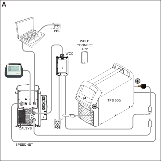
Example layout with TPS 500i: WCC = WeldCube Connector, PoE = Power over Ethernet, CALSYS = Calibration system
Connecting the welding system, WeldCube Connector U/I and calibration system
1Plug the mains cable into the calibration system
2Plug the mains cable into the grid
3Switch on the mains switch
NOTE!
If there is a power connector for the high current socket on the power source, use the adapter for the high current sockets to bayonet (42,0001,4482).
4Connect the (+) power cable to calibration system
5Connect the voltage measurement adapter to the (+) socket of the power source
6Connect the (+) power cable to the voltage measurement adapter
7Connect the sense lead (red) to the calibration system
8Connect the (-) power cable to the calibration system and the WeldCube Connector
9Connect the sense lead (blue) to the calibration system
10Connect the WeldCube Connector return lead cable to the (-) socket on the power source
11Connect the PoE (OUT) to the WeldCube Connector
12Switch on the power source
13Connect the SpeedNet cable to the calibration system and to a free SpeedNet connection socket on the welding system
NOTE!
The WeldCube Connector calibration process requires a second measurement with reversed polarity of the power cables.
The calibration software interrupts the calibration process and issues a message to reverse the polarity of the welding system.
Reverse the polarity of the welding system as shown in figure B below.
After reversing the polarity in the calibration software, continue the calibration process.
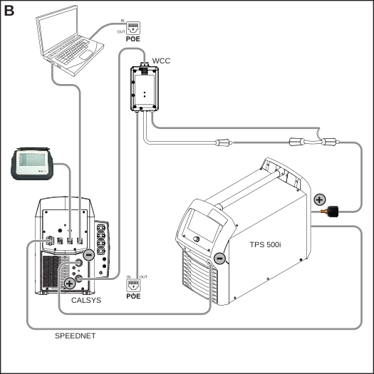
Welding system polarity reversed
14Connect the (+) power cable from the calibration system to the WeldCube Connector
15Connect the WeldCube Connector return lead cable to the voltage measurement adapter (to the (+) socket on the power source)
16Connect the (-) power cable from the calibration system to the (-) socket on the power source
Information on the calibration procedure of the WeldCube Connector U/I
Preliminary settings / device selection:
Under Settings, select the connection to the power source:
o SpeedNet
o ...
Establishing a connection to the WeldCube Connector
(for details see WeldCube Connector operating instructions 42,0426,0363,xx)
- Start WeldConnect app and open menu
- Determine the welding circuit resistance of the welding system incl. WeldCube Connector
- Select WeldCube Connector Setup
- Take smartphone to the WeldCube Connector
- Follow the instructions in the installation wizard (Setup 1 - 7)
Following the 7 setup steps, the WeldCube Connector will be ready to connect to the calibration software.
Click [Establish connection] in the calibration software
Deselect wire speed:
Click on the selection box
Enter the DHCP IP address of the WeldCube Connector
The network settings message is displayed.
Briefly disconnect and reconnect the Ethernet cable between the WeldCube Connector and PoE (OUT)
Set calibration class:
o Precision
o Standard
For details on calibration class, see page (→).
Start the automatic calibration process
When calibration is complete, a message to reverse the polarity of the WeldCube Connector is displayed.
IMPORTANT!
Reverse the polarity of the welding system according to figure B on page (→)
Confirm the message to reverse the polarity of the WeldCube Connector with OK.
The calibration process continues.
WeldCube Connector U/I/WFS Euro system structure
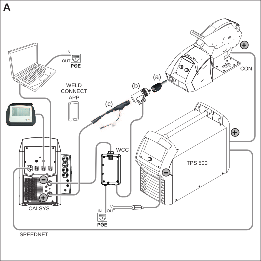
Example layout with TPS 500i: WCC = WeldCube Connector, PoE = Power over Ethernet, CALSYS = Calibration system, CON = Interconnecting hosepack
Connecting the welding system, WeldCube Connector U/I/WFS Euro and calibration system
1Plug the mains cable into the calibration system
2Plug the mains cable into the grid
3Switch on the mains switch
NOTE!
If there is a power connector for the high current socket on the power source, use the adapter for the high current sockets to bayonet (42,0001,4482).
4Connect the wirefeeder to the (+) socket on the power source (for example, using the interconnecting hosepack power cable)
5Connect adapter-ZA FSC-S-G/Euro STD (a) to the wirefeeder
6Connect the WCC Euro wire sensor (b) to the ZA FSC-S-G/Euro STD adapter
7Connect the Euro/central connector with Tuchel socket (c) to the WCC Euro wire sensor
8Connect the (+) power cable to the calibration system and the Euro/central connector adapter with Tuchel socket (c)
9Connect the sense lead (red) to the calibration system
10Connect the (-) power cable to the calibration system and the WeldCube Connector
11Connect the sense lead (blue) to the calibration system
12Connect the WeldCube Connector return lead cable to the (-) socket on the power source
13Connect the WCC Euro wire sensor (a) to the WeldCube Connector
14Connect the PoE (OUT) to the WeldCube Connector
15Switch on the power source
16Connect the SpeedNet cable to the calibration system and to a free SpeedNet connection socket on the welding system
Wire calibration
NOTE!
In conjunction with the WeldCube Connector, wire calibration takes place in the course of the system calibration.
Following the first current-voltage calibration, a prompt to start wire calibration appears in the calibration software.
Before confirming the prompt:
Establish data communication between the power source and the calibration system (LocalNet, SpeedNet, USB, etc.)
Establish data communication between the power source and wirefeeder (LocalNet, SpeedNet, USB, etc.)
Establish data communication between the welding wire calibration system and the calibration system
Convert the welding system as shown in figure B below:
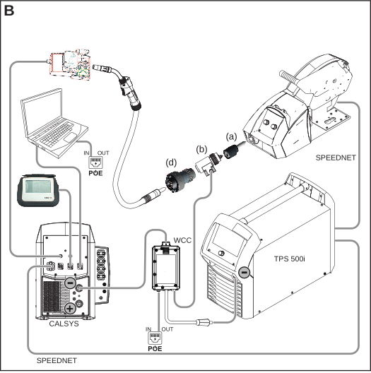
17Connect the connection cable to the welding wire calibration system and to the calibration system
IMPORTANT! A maximum of 3 connection cables (max. 15 m) can be used to connect the welding wire calibration system and the calibration system!
IMPORTANT! A maximum of 3 connection cables (max. 15 m) can be used to connect the welding wire calibration system and the calibration system!
18Disconnect the (+) power cable from the Euro/central connector adapter with Tuchel socket (c)
19Disconnect the Euro/central connector adapter with Tuchel socket (c) from the WCC Euro wire sensor (b)
20Connect the ZA Euro/FSC adapter (d) to the WCC Euro wire sensor (b)
21Connect welding torch to ZA Euro/FSC (d) adapter
NOTE!
The WeldCube Connector calibration process requires a second measurement with reversed polarity of the power cables.
The calibration software interrupts the calibration process and issues a message to reverse the polarity of the welding system.
Reverse the polarity of the welding system as shown in figure C below.
After reversing the polarity in the calibration software, continue the calibration process.
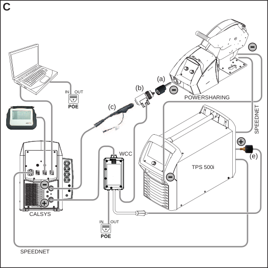
22Disconnect the welding torch from the ZA Euro/FSC (d) adapter
23Disconnect the ZA Euro/FSC adapter (d) from the WCC Euro wire sensor (b)
24Connect the Euro/central connector with Tuchel socket (c) to the WCC Euro wire sensor (b)
25Connect the (+) power cable from the calibration system to the WeldCube Connector
26Connect the (-) power cable to the calibration system on the Euro/central connector adapter with Tuchel socket (c)
27Connect the WeldCube Connector return lead cable to the (+) socket of the power source using the PowerConnector/Dinse adapter (e)
28Disconnect the power cable of the interconnecting hosepack from the wirefeeder
29Connect the power sharing cable to the (-) socket of the power source
30Connect the power sharing cable to the power connector of the wirefeeder
Information on the calibration procedure of the WeldCube Connector U/I/WFS Euro
Preliminary settings / device selection:
Under Settings, select the connection to the power source:
o SpeedNet
o ...
Establishing a connection to the WeldCube Connector
(for details see WeldCube Connector operating instructions 42,0426,0363,xx)
- Start WeldConnect app and open menu
- Determine the welding circuit resistance of the welding system incl. WeldCube Connector
- Select WeldCube Connector Setup
- Take smartphone to the WeldCube Connector
- Follow the instructions in the installation wizard (Setup 1 - 7)
Following the 7 setup steps, the WeldCube Connector will be ready to connect to the calibration software.
Click [Establish connection] in the calibration software
Enter the DHCP IP address of the WeldCube Connector
The network settings message is displayed.
Briefly disconnect and reconnect the Ethernet cable between the WeldCube Connector and PoE (OUT)
Define the calibration class:
o Precision
o Standard
For details on the calibration class, see page (→).
Start the automatic calibration process
IMPORTANT! If the calibration process is interrupted before the welding wire has been calibrated, a corresponding notification is displayed.
Convert welding system for wire calibration according to figure B from page (→)
CAUTION!
Danger from welding wire emerging at speed.
This can result in personal injury.
Keep head and body away from the welding wire calibration system.
Wear suitable protective goggles.
Make sure that when the welding wire emerges, it does not touch any electrically conducting, earthed or live parts.
Make sure that there is sufficient space for the emerging welding wire (approx. 10 m).
Make sure that no one is endangered by the emerging welding wire.
Start wire calibration
When wire calibration is complete, a message to reverse the polarity of the WeldCube Connector is displayed.
IMPORTANT! Reverse the polarity of the welding system according to figure C from page (→)
Confirm the message to change the polarity of the WeldCube Connector with OK. The calibration process continues.
Information on the calibration procedure of the WeldCube Connector U/I/WFS
NOTE!
The system structure for the WeldCube Connector U/I/WFS differs from the system structure of the WeldCube Connector U/I/WFS Euro as follows:
The WCC wire sensor is installed directly in the TransSteel power source or the VR 5000 wirefeeder.
The power sharing cable is not needed, a simple power cable with bayonet latch is sufficient.
For wire calibration, an FSC welding torch is connected directly to the power source or wirefeeder.
The ZA FSC-S-G/Euro STD and Euro/central connection adapters with Tuchel socket are not required for this.
Connection to power source: LocalNet
Otherwise, the WeldCube Connector U/I/WFS calibration process is the same as the calibration process for the WeldCube Connector U/IWFS Euro.
Calibration of the gas supply
Prerequisite for the calibration of gas supplies
The calibration of gas supplies is only possible if one of the following devices or gas controls is present in the welding system:
LocalNet
- PlasmaModule 10 - 4,075,146
- External gas control 0.2-10.0 l/mi - 4,045,995
- I-kit digital gas sensor Gas 10 - 4,100,538 *
- External gas control 5-30 l/mi - 4,045,997
| * | The gas flow must be adjusted manually. |
SpeedNet
- OPT/i gas control - 4,100,969
- OPT/i WF gas flow sensor - 4,101,150
- OPT/i gas control Compact - 4,101,422
- OPT/i TIG gas control - 4,101,259
- OPT/i WF TWIN gas control - 4,101,158
Prerequisite for the calibration of gas supplies
The calibration of gas supplies is only possible if one of the following devices or gas controls is present in the welding system:
LocalNet
- PlasmaModule 10 - 4,075,146
- External gas control 0.2-10.0 l/mi - 4,045,995
- I-kit digital gas sensor Gas 10 - 4,100,538 *
- External gas control 5-30 l/mi - 4,045,997
| * | The gas flow must be adjusted manually. |
SpeedNet
- OPT/i gas control - 4,100,969
- OPT/i WF gas flow sensor - 4,101,150
- OPT/i gas control Compact - 4,101,422
- OPT/i TIG gas control - 4,101,259
- OPT/i WF TWIN gas control - 4,101,158
System layout
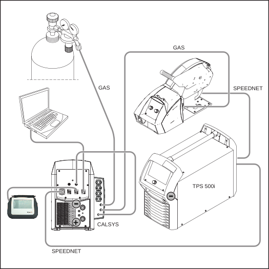
Example layout with TPS 500i: CALSYS = Calibration system, CON = Interconnecting hosepack, GAS = Gas hose
NOTE!
For iWave power sources, connect the gas hose from the Gas OUT connector on the interface calibration system directly to the power source
Connect gas supply with interface calibration system, calibration system and power source
1Connect the gas hose to the gas pressure regulator and to the Gas IN connection on the interface calibration system
max. supply pressure: 5 bar
max. supply pressure: 5 bar
2Connect the gas hose to the wirefeeder / power source and to the Gas OUT connection on the interface calibration system
3Connect the gas connection on the calibration system with the data connection on the calibration system interface
4Connect the power source with the calibration system
Information on the calibration procedure
Calibration of a gas supply is usually done as the last step of complete welding system calibration:
- Calibrate power source (welding current, welding voltage)
- Calibrate wirefeeder (wire speed)
- Calibration of the gas supply
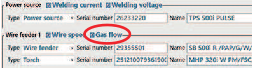
To calibrate a gas supply, the checkbox for gas flow must be activated in the calibration software for the wirefeeder.
Enter shielding gas composition
Start calibration
Troubleshooting
Troubleshooting
The status indicator is not lit up
Troubleshooting
The status indicator is not lit up
The status indicator is not lit up
No power supply
| Cause: | Mains cable not connected |
| Remedy: | Connect the mains cable |
| Cause: | Faulty mains cable |
| Remedy: | Check the mains cable and replace if necessary |
| Cause: | Fuses F1 / F4 / F5 have tripped |
| Remedy: | Switch off the device, disconnect it from the mains, and check fuses, e.g.: using a multimeter or visual inspection (burnt-through metal strips) |
The status indicator lights up red
An error has occurred during the calibration process
A description of the error is displayed by the calibration software.
| Cause: | Various |
| Remedy: | Follow the instructions in the calibration software Contact our After-Sales Service team if the error is constantly present. |
No connection
No connection between power source and calibration software
| Cause: | Error during installation |
| Remedy: | Check that all cables are connected. Check whether the TwinCat Route has been set properly. Check whether the network adapter has been configured correctly. Check the Firewall settings. Check that all drivers are installed. Check all installation steps in general |
No USB/SpeedNet connection
No USB/SpeedNet connection between power source and calibration software
| Cause: | USB connection error |
| Remedy: | Check that the USB Ethernet adapters are properly plugged into the power source and calibration system. Check the Ethernet connection cable for any possible damage and for functionality. Check that the Ethernet connection cable is connected correctly to the USB Ethernet adapters. Check that the DHCP server is running (icon in the task bar!). If the DHCP server is not running, restart the software and check the network settings. Disconnect the USB briefly from the power source and reconnect it again. |
Technical data
Technical data
Calibration system 2.0
Mains voltage | 100 - 240 V AC |
Mains voltage tolerance | +15 / -10 % |
Mains frequency | 50/60 Hz |
Mains fuse protection (slow-blow) | 4 A |
Primary current | 3 A @ 100 V AC |
cos phi power factor | 0.99 |
Internal power supply | 24 V DC +/- 1% |
Output current | 10 A (-25 °C - +55 °C) |
Max. permissible loading of the sockets | 8 A |
Degree of protection | IP 20 |
Type of cooling | AF |
Max. permissible current of the load | 600 A |
Max. permissible loading of the load | 24 kW for 20 s |
Max. permissible voltage of the load | 113 V peak |
EMC device class | EN 61010 -1:2010 |
Safety symbols | CE |
Dimensions l x w x h | 686 x 304 x 497 mm |
Total dimensions (with trolley) | 1103 x 738 x 1017 mm |
Weight | 31.5 kg |
Total weight (with trolley) | 120 kg |
Ambient temperature | 0 – 40 °C |
Load resistance | 8 x 480 mOhm parallel |
Technical data
Calibration system 2.0
Mains voltage | 100 - 240 V AC |
Mains voltage tolerance | +15 / -10 % |
Mains frequency | 50/60 Hz |
Mains fuse protection (slow-blow) | 4 A |
Primary current | 3 A @ 100 V AC |
cos phi power factor | 0.99 |
Internal power supply | 24 V DC +/- 1% |
Output current | 10 A (-25 °C - +55 °C) |
Max. permissible loading of the sockets | 8 A |
Degree of protection | IP 20 |
Type of cooling | AF |
Max. permissible current of the load | 600 A |
Max. permissible loading of the load | 24 kW for 20 s |
Max. permissible voltage of the load | 113 V peak |
EMC device class | EN 61010 -1:2010 |
Safety symbols | CE |
Dimensions l x w x h | 686 x 304 x 497 mm |
Total dimensions (with trolley) | 1103 x 738 x 1017 mm |
Weight | 31.5 kg |
Total weight (with trolley) | 120 kg |
Ambient temperature | 0 – 40 °C |
Load resistance | 8 x 480 mOhm parallel |
Calibration system 2.0
Mains voltage | 100 - 240 V AC |
Mains voltage tolerance | +15 / -10 % |
Mains frequency | 50/60 Hz |
Mains fuse protection (slow-blow) | 4 A |
Primary current | 3 A @ 100 V AC |
cos phi power factor | 0.99 |
Internal power supply | 24 V DC +/- 1% |
Output current | 10 A (-25 °C - +55 °C) |
Max. permissible loading of the sockets | 8 A |
Degree of protection | IP 20 |
Type of cooling | AF |
Max. permissible current of the load | 600 A |
Max. permissible loading of the load | 24 kW for 20 s |
Max. permissible voltage of the load | 113 V peak |
EMC device class | EN 61010 -1:2010 |
Safety symbols | CE |
Dimensions l x w x h | 686 x 304 x 497 mm |
Total dimensions (with trolley) | 1103 x 738 x 1017 mm |
Weight | 31.5 kg |
Total weight (with trolley) | 120 kg |
Ambient temperature | 0 – 40 °C |
Load resistance | 8 x 480 mOhm parallel |
Wire speed measuring system
Operating voltage | 5 - 30 V DC |
Open-circuit current | 55 mA |
Wire speed | 0 - max. 30 m/min |
Degree of protection | IP 20 |
EMC device class | EN 61010 -1:2010 |
Safety symbols | CE |
Weight | 1.5 kg |
Ambient temperature | 0 – 40 °C |
Fuse protection | T2A |
Interface calibration system
Operating voltage | 24 V DC |
Protection class | IP 20 |
EMC emission class | EN 61010-1:2010 |
Safety symbols | CE |
Dimensions L x W x H | 466 x 355 x 85 mm |
Weight (incl. gas calibration system I-kit) | 3.85 kg |
Ambient temperature | 0 - 40 °C |
Gas calibration system I-kit
The "Gas calibration system" installation set is installed in the interface calibration system at the factory when ordered.
Operating voltage | 18–30 V DC |
Max. current consumption | 100 mA |
Max. operating pressure | 11 bar |
Measuring range | 0 - 60 l/min |
Ambient temperature | 0 - 40 °C |
Gas temperature | 0 - 50 °C |
Fuse protection | T2A |
Calibration classes of Fronius devices
Device type | Calibration class | AC | Device type | Calibration class | AC |
|---|---|---|---|---|---|
AccuPocket | Precision | 230 | TransTig 1600 | Precision | 230 |
iWave 190-230 | Precision | 230 | TransTig 170 | Standard | 230 |
iWave 300-500 | Precision | 400 | TransTig 1700 | Precision | 230 |
MagicWave 200 | Precision | 400 | TransTig 1750 Puls G/F | Precision | 230 |
MagicWave 2600 | Precision | 400 | TransTig 200 | Precision | 230 |
MagicWave 300 | Precision | 400 | TransTig 2000 | Precision | 230 |
MagicWave 3000 | Precision | 400 | TransTig 210 | Standard | 230 |
MagicWave 3000 230V | Precision | 230 | TransTig 2600 | Precision | 400 |
MagicWave 450 | Precision | 400 | TransTig 330 | Precision | 400 |
MW/TT 800-2200 | Precision | 230 | TransTig 450 | Precision | 400 |
MW/TT/TPS 2500-5000 | Precision | 400 | TS 330 | Precision | 400 |
TIME Synergic | Precision | 400 | TS 450 | Precision | 400 |
CMT 4000 Advanced | Precision | 400 | VarioStar 267 | Precision | 400 |
TPS 320i-600i | Precision | 400 | VarioStar 337 | Precision | 400 |
TPS 270i C / 320i C | Precision | 400 | VarioStar 337-2 | Precision | 400 |
TPS 330 | Precision | 400 | VarioStar 3400 | Standard | 400 |
TPS 450 | Precision | 400 | VarioStar 3400-2 | Standard | 400 |
TransArc 1000 | Precision | 400 | VarioStar 357 | Precision | 400 |
TransArc 500 | Precision | 400 | VarioStar 357-2 | Precision | 400 |
TransPocket 1400 | Standard | 230 | VarioStar 4000 | Standard | 400 |
TransPocket 150 | Precision | 230 | VarioStar 4000-2 | Standard | 400 |
TransPocket 1500 | Standard | 230 | VarioStar 447 | Precision | 400 |
TransPocket 180 | Precision | 230 | VarioStar 447-2 | Precision | 400 |
TransPocket 2000 | Standard | 400 | VarioStar 457 | Precision | 400 |
TransPocket 2500 | Standard | 400 | VarioStar 457-2 | Precision | 400 |
TransPocket 3500 | Standard | 400 | VarioStar 5000 | Standard | 400 |
TransPocket 4000 / 5000 CEL | Standard | 400 | VarioStar 5000-2 | Standard | 400 |
TS 4000 / 5000 | Standard | 400 |
|
|
|
TransSteel 2200c | Precision | 230 |
|
|
|
TransSteel 2500-5000 | Standard | 400 |
|
|
|
Device type | Calibration class | AC | Device type | Calibration class | AC |
|---|---|---|---|---|---|
AccuPocket | Precision | 230 | TransTig 1600 | Precision | 230 |
iWave 190-230 | Precision | 230 | TransTig 170 | Standard | 230 |
iWave 300-500 | Precision | 400 | TransTig 1700 | Precision | 230 |
MagicWave 200 | Precision | 400 | TransTig 1750 Puls G/F | Precision | 230 |
MagicWave 2600 | Precision | 400 | TransTig 200 | Precision | 230 |
MagicWave 300 | Precision | 400 | TransTig 2000 | Precision | 230 |
MagicWave 3000 | Precision | 400 | TransTig 210 | Standard | 230 |
MagicWave 3000 230V | Precision | 230 | TransTig 2600 | Precision | 400 |
MagicWave 450 | Precision | 400 | TransTig 330 | Precision | 400 |
MW/TT 800-2200 | Precision | 230 | TransTig 450 | Precision | 400 |
MW/TT/TPS 2500-5000 | Precision | 400 | TS 330 | Precision | 400 |
TIME Synergic | Precision | 400 | TS 450 | Precision | 400 |
CMT 4000 Advanced | Precision | 400 | VarioStar 267 | Precision | 400 |
TPS 320i-600i | Precision | 400 | VarioStar 337 | Precision | 400 |
TPS 270i C / 320i C | Precision | 400 | VarioStar 337-2 | Precision | 400 |
TPS 330 | Precision | 400 | VarioStar 3400 | Standard | 400 |
TPS 450 | Precision | 400 | VarioStar 3400-2 | Standard | 400 |
TransArc 1000 | Precision | 400 | VarioStar 357 | Precision | 400 |
TransArc 500 | Precision | 400 | VarioStar 357-2 | Precision | 400 |
TransPocket 1400 | Standard | 230 | VarioStar 4000 | Standard | 400 |
TransPocket 150 | Precision | 230 | VarioStar 4000-2 | Standard | 400 |
TransPocket 1500 | Standard | 230 | VarioStar 447 | Precision | 400 |
TransPocket 180 | Precision | 230 | VarioStar 447-2 | Precision | 400 |
TransPocket 2000 | Standard | 400 | VarioStar 457 | Precision | 400 |
TransPocket 2500 | Standard | 400 | VarioStar 457-2 | Precision | 400 |
TransPocket 3500 | Standard | 400 | VarioStar 5000 | Standard | 400 |
TransPocket 4000 / 5000 CEL | Standard | 400 | VarioStar 5000-2 | Standard | 400 |
TS 4000 / 5000 | Standard | 400 |
|
|
|
TransSteel 2200c | Precision | 230 |
|
|
|
TransSteel 2500-5000 | Standard | 400 |
|
|
|