Fronius Smart Meter WR
download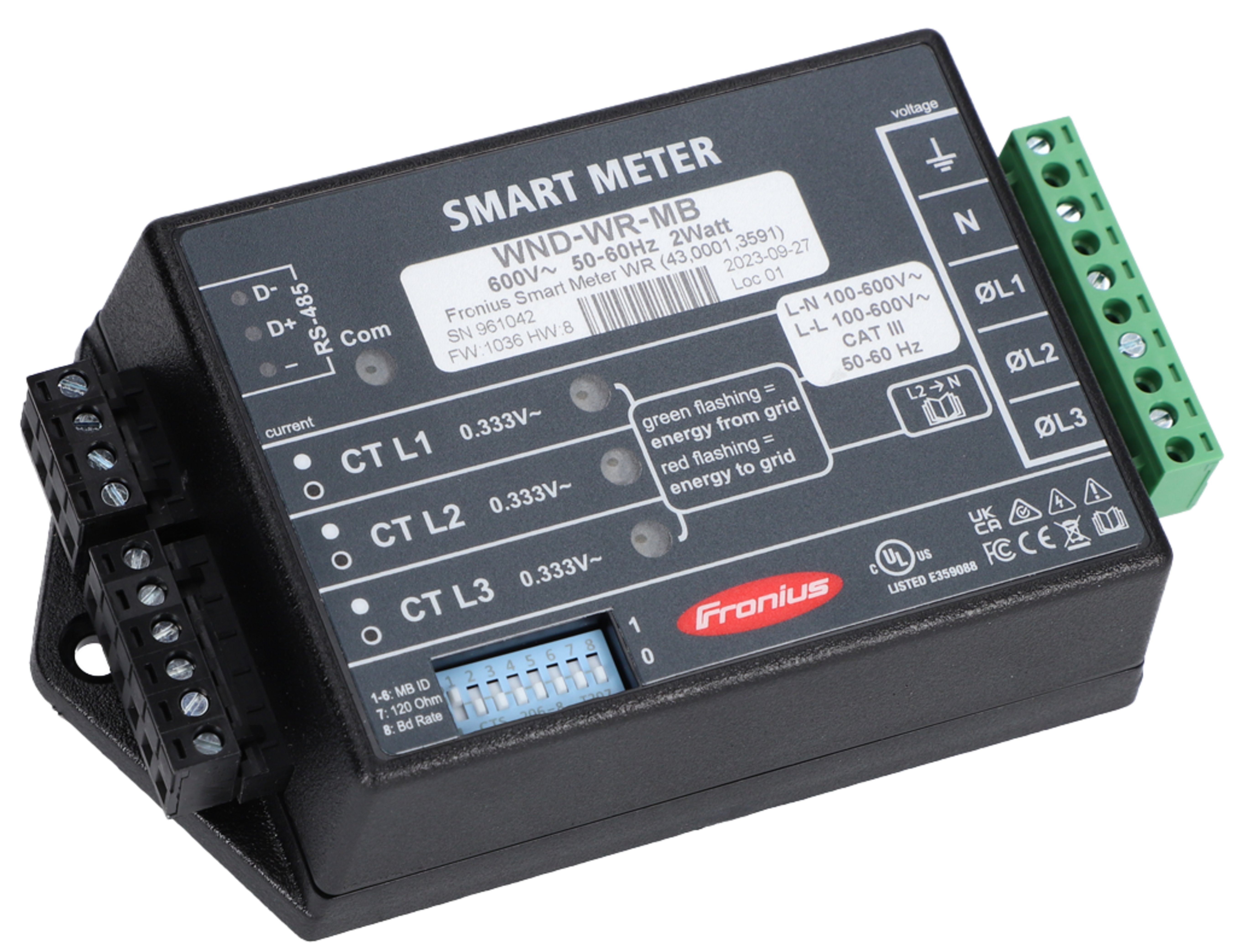
Warnings are intended to warn people of possible injuries and to avoid personal injury and damage to the product. They relate to individual actions with and on the product.
Indicates an immediately dangerous situation.
Serious injury or death will result if the danger is not avoided.
Action step to escape the situation.
Indicates a potentially dangerous situation.
Serious injury or death may result if the danger is not avoided.
Action step to escape the situation.
Indicates a potentially dangerous situation.
Minor or moderate injury may result if the danger is not avoided.
Action step to escape the situation.
Indicates a situation that may result in property damage.
If the situation is not avoided, impaired work results, material damage to the product or other property are the possible consequences.
Action step to avoid the situation.
Safety instructions are designed to ensure safe product use. They are preventive and help to inform users about the fundamental risks involved when dealing with the product. They do not refer specifically to individual actions with and on the product.
The device has been manufactured in line with the state of the art and according to recognized safety standards.
Incorrect operation or misuse
Serious to fatal injuries to the operator or third parties as well as damage to the device and other property of the operator may result.
All persons involved in the commissioning, maintenance, and servicing of the device must be appropriately qualified and have knowledge of working with electrical installations.
Read these operating instructions in full and follow them carefully and precisely.
The operating instructions must always be kept to hand wherever the device is being used.
IMPORTANT!
Labels, warning notices, and safety symbols are located on the device. A description can be found in these operating instructions.
Tampered-with and non-functioning protection devices
Serious to fatal injuries as well as damage to the device and other property of the operator may result.
Never bypass or disable protection devices.
Any protection devices that are not fully functional must be repaired by an authorized specialist before the device is switched on.
Loose, damaged, or under-dimensioned cables
An electric shock can be fatal.
Use undamaged, insulated, and adequately dimensioned cables.
Fasten the cables according to the specifications in the operating instructions.
Loose, damaged, or under-dimensioned cables must be repaired or replaced immediately by an authorized specialist.
Installations or modifications to the device
The device may be damaged
Do not carry out any alterations, installations, or modifications to the device without first obtaining the manufacturer's permission.
Damaged components must be replaced.
Only use original spare parts.
The Operating Instructions must always be kept on hand wherever the device is being used. In addition to the Operating Instructions, all applicable local rules and regulations regarding accident prevention and environmental protection must also be followed.
All safety and danger notices on the deviceThe terminals can reach high temperatures.
Only operate the device when all protection devices are fully functional. If the protection devices are not fully functional, there is a risk ofAny safety devices that are not functioning properly must be repaired by an authorized specialist before the device is switched on.
Never bypass or disable protection devices.
For the location of the safety and danger notices on the device, refer to the section headed “General” in the Operating Instructions for the device.
Any equipment malfunctions which might impair safety must be remedied immediately before the device is turned on.
Your personal safety is at stake!
Operation or storage of the machine outside the stipulated area will be deemed as not in accordance with the intended purpose.
For exact information on permitted environmental conditions, please refer to the technical data.
Safety symbols: | |
 | To avoid electric shocks:
|
 | RCM Symbol - The product complies with the Australian laws. |
Safety symbols: | |
| To avoid electric shocks:
|
| RCM Symbol - The product complies with the Australian laws. |
The conventions regarding how information is presented in the document, which are set out below, have been defined in order to increase the readability and comprehensibility of the document.
Application notes
IMPORTANT! Indicates application notes and other useful information. It does not indicate a harmful or dangerous situation.
Software
Software functions and elements of a graphical user interface (e.g., buttons, menu items) are highlighted in the text with this mark up.
Example: Click Save.
Instructions for action
This document provides detailed information and instructions to ensure that people can use the machine safely and efficiently.
The information is intended for the following groups of people:Regardless of any qualifications, only perform the activities listed in this document.
The definition of professional qualifications and their applicability are subject to national law.
Data security for network and Internet connection
Unsecured networks and a lack of safeguards can result in data loss and unauthorized access. Observe the following points for safe operation:
Operate inverters and system components on a private, secure network. A WiFi network is considered secure if security standard WPA 2 is satisfied as a minimum.
Keep the network devices (e.g., WiFi routers) up to date with the latest technology.
Keep the software and/or firmware updated.
Use a wired network to ensure a stable data connection.
For security reasons, do not make inverters and system components accessible from the Internet via port forwarding or Port Address Translation (PAT).
Use the solutions provided by Fronius for monitoring and remote configuration.
The optional communication protocol Modbus TCP/IP1) is an unsecured interface. Only use Modbus TCP/IP if no other secured data communication protocol (MQTT2)) is possible (e.g., compatibility with older Smart Meters).
1) TCP/IP - Transmission Control Protocol/Internet Protocol
2) MQTT - Message Queuing Telemetry Protocol
When you connect your device (and any associated devices) to the internet, the following device and operating data (device ID/identifier, device IP address, device time, configuration settings, hardware and software information, device status log files, serial number) is sent automatically to
Fronius International GmbH, Froniusstraße 1, 4643 Pettenbach, Austria, telephone +43(0) 7242241-0, email: contact@fronius.com (controller)
and stored.
The processing of this device and operating data is carried out for the purpose of ensuring the operational safety of the device (time synchronization, provision of updates). This processing is therefore necessary for the functionality of the device and thus for the fulfillment of the contract (Art. 6 (1) (b) GDPR).
If you do not wish to have such data processed, you must manually disable the device's internet connection.
In addition, the device and operating data is also processed for the purpose of providing services as part of a supplementary digital service for your device (such as solar.web or similar) as soon as you have registered your device with such a digital service (identification). This data is processed to provide the requested digital services and is therefore necessary for the fulfillment of the contract (Art. 6 (1) (b) GDPR).
Furthermore, this data processing is also carried out for maintenance and support purposes and for handling customer concerns as well as in warranty and guarantee cases (only in individual cases and given connection between device and internet). In this context, the device and operating data may also be passed on to our cooperation partners (third-party providers and suppliers). The processing of this data is necessary for maintenance and support purposes or for processing warranty and guarantee cases and thus for the fulfillment of the contract (Art. 6 (1) (b) GDPR).
Device and operating data are also processed for analysis and diagnostic purposes in order to gain insights into the functionality of the devices and improve them accordingly. This data processing is based on our legitimate interest (Art. 6 (1) (f) GDPR).
We store this data for as long as it is necessary to fulfill the existing contract with you. Any storage beyond this is carried out for legal reasons or if we have a legitimate interest in doing so. For more information on data processing for the solar.web-digital service, as well as our general privacy policy and your rights as a data subject, please visit https://www.fronius.com.
Fronius International GmbH retains the copyrights of these operating instructions.
Text, illustrations, and other media correspond to the technical state of the art at the time of publication. Fronius reserves the right to make changes. If you have any suggestions for improvement or have found a mistake in this document, we would be most grateful for your comments.
FCC
This device corresponds to the limit values for a digital device of class B in accordance with Part 15 of the FCC regulations. The limit values should provide adequate protection against harmful interference in homes. This device creates and uses high frequency energy and can interfere with radio communications when not used in accordance with the instructions. However, there is no guarantee against interference occurring in a particular installation.
If this device interferes with radio or television reception when turning the device on and off, it is recommended that the user solve this with one or more of the following measures:
Industry Canada RSS
The device corresponds to the license-free Industry Canada RSS standards. Operation is subject to the following conditions:
(1) The device may not cause harmful interference
(2) The device must accept any interference received, including interference that may cause undesired operation.
This product is intended for use and sale outside the Province of Québec. It does not meet the French language documentation and labeling requirements of Québec's Charter of the French Language. Accordingly, Fronius International GmbH does not offer this product for sale to, or for delivery to, any address within the Province of Québec.
By placing an order, the customer represents and warrants that they are not purchasing the product for use or resale within Québec. Fronius International GmbH disclaims all liability and warranty obligations for any products operated in Québec in violation of these restrictions.
Used equipment and batteries must be returned to the distributor or an authorized local collection system. Do not dispose of batteries with domestic waste. Protect batteries from high temperatures, direct sunlight, moisture and corrosive environments.
Arrange for the safe collection and proper disposal of damaged, leaking or used batteries by a battery recycling company or the Fronius Service Partner.
In addition, it should be noted that batteries contain substances that, if disposed of improperly, can have a significant negative impact on the environment as well as on human health and the safety of persons, in particular due to the leakage of hazardous substances such as heavy metals or electrolytes, which can contaminate soil, water and air.
This ensures environmental protection and the sustainable use of natural resources.Packaging materialsThe Fronius Smart Meter is a bidirectional electricity meter for optimizing self-consumption and recording a household's load characteristic curve. Together with a Fronius inverter or Fronius Datamanager 2.0 and a Fronius data interface, the Fronius Smart Meter allows you to view your own power consumption. The meter measures the energy flow to the loads or to the public grid and forwards the information to the Fronius inverter or Fronius Datamanager 2.0 via the Modbus RTU/RS485 interface.
Danger due to non-compliance with the safety instructions
Risk of injury and damage to the device as a result.
Follow all safety instructions.
Switch off the power supply before establishing the mains connection.
The Fronius Smart Meter is a bidirectional electricity meter for optimizing self-consumption and recording a household's load characteristic curve. Together with a Fronius inverter or Fronius Datamanager 2.0 and a Fronius data interface, the Fronius Smart Meter allows you to view your own power consumption. The meter measures the energy flow to the loads or to the public grid and forwards the information to the Fronius inverter or Fronius Datamanager 2.0 via the Modbus RTU/RS485 interface.
Danger due to non-compliance with the safety instructions
Risk of injury and damage to the device as a result.
Follow all safety instructions.
Switch off the power supply before establishing the mains connection.
The Fronius Smart Meter can be installed at two possible locations in the system, at the feed-in point and at the consumption point.
Positioning at the feed-in point
The positioning of the Fronius Smart Meter at the feed-in point.

Positioning at the consumption point
The positioning of the Fronius Smart Meter at the consumption point.


| (1) | Product name |
| (2) | Nominal voltage, operating frequencies, measurement category |
| (3) | AC connection area |
| (4) | Note single-phase grids |
| (5) | Power status LED
|
| (6) | DIP-switch:
|
| (7) | CT connection area |
| (8) | Data communication LED |
| (9) | Data communication connection area |
The Fronius Smart meter has two mounting holes spaced 5.4 in. (137 mm) apart (center-to-center). These mounting holes are normally obscured by the detachable screw terminals. Remove the screw terminals to mark the hole positions and mount the meter.
Self-tapping sheet metal screws are included. Do not over-tighten the screws, as long-term stress on the case can cause cracking.

The Fronius Smart Meter is considered “permanently connected equipment“ and requires a disconnect means (circuit breaker, switch or disconnect) and overcurrent protection (fuse or circuit breaker).
The Fronius Smart Meter only draws 10-30 mA, so the rating of any switches, disconnects, fuses and / or circuit breakers is determined by the wire gauge, the mains voltage and the current interrupting rating required.
Connect each conductor to the appropriate phase; also connect ground and neutral (if applicable). The neutral connection “N“ is not required on delta models but we recommend connecting it to ground if neutral is not present.
The screw terminal can handle wire up to 12 AWG. Connect each voltage line to the green terminal block as shown in the following figures. After the voltage lines have been connected, make sure both terminal blocks are fully seated in the Fronius Smart Meter.
When power is first applied, check that the LEDs behave normally. If you see LEDs flashing red-green-red-green, the voltage is too high for this model, so disconnect the power switch immediately!
Single-Phase Three-Wire (Mid-Point Neutral) / Two-Phase Australia

Single-Phase Two-Wire without Neutral

Single-Phase Two-Wire with Neutral

Three-Phase Four-Wire Wye

Three-Phase Three-Wire Delta without Neutral

Three-Phase Four-Wire Stinger

Three-Phase Two-Wire Corner Grounded Delta

The current transformer must generate 333.33 millivolts AC at rated current. See the current transformer data sheets for CT ratings (Fronius CT, 41,0010,0104 / 41,0010,0105 / 41,0010,0232).
Install the CTs around the conductor to be measured and connect the CT leads to the Fronius Smart Meter. Always turn off power before disconnecting any live conductors. Put the line conductors through the CTs as shown in the previous section.
CTs are directional. If they are mounted backwards or with their white and black wires swapped the measured power will be negative. The status LEDs indicate negative measured power by flashing red.
Split-core CTs can be opened for installation around the conductor. A nylon cable tie may be secured around the CT to prevent inadvertent opening.
The device can be used for power control systems in accordance with the UL 3141 standard. The additionally required current transformers must comply with the specifications of the UL 2808 standard.
Power Control Systems
Power Control Systems according to UL 3141 are only available for installations in the USA, Canada and Mexico.
The current transformers connect to the six position black screw terminal block. Connect the white and black CT wires to the Fronius Smart Meter terminals marked CT L1, CT L2 and CT L3. Excess length may be trimmed from the wires if desired. Connect each CT with the white wire aligned with the white dot on the label and the black wire aligned with the black dot. Note the order in which the phases are connected, as the line voltage phases must match the current phases for accurate power measurement.
Fronius SnapINveter:
Connect the data communication ports of the Fronius Smart Meter to the Fronius system monitoring in the inverter. Several Smart Meters can be installed in the system, see chapter Multi meter system – Fronius SnapINverter on page (→)

Fronius GEN24 inverter:
Connect the data communication ports of the Fronius Smart Meter to the Modbus interface of the Fronius GEN24 inverter. Several Smart Meters can be installed in the system, see chapter Multi meter system - Fronius GEN24 inverter on page (→)

The Fronius Smart Meter must be connected to the Fronius Datamanager. If only one Fronius Smart Meter is installed, the Modbus Address is 1.
DIP Switch | 1 | 2 | 3 | 4 | 5 | 6 | 7 | 8 |
Up (1) value | 1 | 2 | 4 | 8 | 16 | 32 | R 120 Ohm | Baud Rate |
Examples

Modbus Adress 1 | ||||||
DIP Switch | 1 | 2 | 3 | 4 | 5 | 6 |
Position | 1 | 0 | 0 | 0 | 0 | 0 |

Modbus Adress 2 | ||||||
DIP Switch | 1 | 2 | 3 | 4 | 5 | 6 |
Position | 0 | 1 | 0 | 0 | 0 | 0 |

Modbus Adress 3 (value 1 + 2 = 3) | ||||||
DIP Switch | 1 | 2 | 3 | 4 | 5 | 6 |
Position | 1 | 1 | 0 | 0 | 0 | 0 |

Modbus Adress 4 | ||||||
DIP Switch | 1 | 2 | 3 | 4 | 5 | 6 |
Position | 0 | 0 | 1 | 0 | 0 | 0 |

Modbus Adress 7 (value 1 + 2 + 4 = 7) | ||||||
DIP Switch | 1 | 2 | 3 | 4 | 5 | 6 |
Position | 1 | 1 | 1 | 0 | 0 | 0 |

Modbus Adress 20 (value 4 + 16 = 20) | ||||||
DIP Switch | 1 | 2 | 3 | 4 | 5 | 6 |
Position | 0 | 0 | 1 | 0 | 1 | 0 |
 | Inverter in the system |
 | Meter - Fronius Smart Meter WR |
 | Fronius or third-party device, connection via Modbus RTU |
 | Termination resistance |
The system might work without terminating resistors. Due to interferences, the use of terminating resistors according to the following schemes are recommended.

Activate the Fronius Smart Meter terminating resistor (R 120 Ohm) by switching pin 7 to ON (1).


Select the baud rate by setting DIP switch position 8 (see below). The change will take effect immediately.

Baud Rate | DIP Switch 8 |
9600 (default) | 0 (OFF) |
38400 | 1 (ON) |
 | Grid |
| Inverter in the system |
 | Utility meter |
 | Primary meter |
 | Secondary meter |
| Modbus RTU, Third-party device |
 | Loads in the system |
 | Additional loads in the system |
 | Additional producers in the system |
| Terminating resistor |
A maximum of 4 Modbus stations can be connected to the Modbus connection terminal.
IMPORTANT!
Only one primary meter, one battery and one Ohmpilot can be connected per inverter. Due to the high data transfer of the battery, the battery occupies 2 subscribers.
Example:
Input | Battery | Fronius | Number | Number |
|---|---|---|---|---|
Modbus |  | | 1 | 0 |
|  | 1 | 1 | |
| | 1 | 2 | |
| | 1 | 3 |
If several Fronius Smart Meters are installed, set a separate address for each Smart Meter. The primary meter always receives the address 1. Number all other meters consecutively in the address range from 2 to 14. Different Fronius Smart Meter power categories can be used together.
IMPORTANT! Use a maximum of three secondary meters in a system. To avoid interference, install the terminating resistors as described in chapter Terminating Resistors.


The inputs M0 and M1 can be freely selected. A maximum of 4 Modbus participants can be connected to the Modbus terminal on the inputs M0 and M1.
IMPORTANT!
Only one primary meter, one battery and one Ohmpilot can be connected per inverter. Due to the high data transfer of the battery, the battery occupies 2 subscribers.
Example 1:
Input | Battery | Fronius | Number | Number |
|---|---|---|---|---|
Modbus 0 | | | 0 | 4 |
| | 0 | 2 | |
| | 0 | 1 | |
Modbus 1 | | | 1 | 3 |
Example 2:
Input | Battery | Fronius | Number | Number |
|---|---|---|---|---|
Modbus 0 | | | 1 | 3 |
Modbus 1 | | | 0 | 4 |
| | 0 | 2 | |
| | 0 | 1 |
If several Fronius Smart Meters are installed, a separate address must be set for each one (see Set the address of the Fronius Smart Meter on page (→)). The primary meter always receives the address 1. All other meters are numbered consecutively in the address range from 2 to 14. Different Fronius Smart Meter power categories can be used together.
IMPORTANT!
Use no more than Use 7 secondary meters in the system. To avoid interference, it is recommended to install the terminating resistors according to the chapter Terminating Resistors on page (→).


IMPORTANT! Settings in the "Meter" menu item may only be entered by staff trained to do so!
The service password must be entered for the "Meter" menu item.
Three-phase or one-phase Fronius Smart Meters may be used. In both cases, selection is made via the "Fronius Smart Meter" item. The Fronius Datamanager automatically detects the meter type.
One primary meter and several secondary meters can be selected. The primary meter must be configured before a secondary meter can be chosen.
Access Point:
 key. key.
LAN:
 to save the settings.
The Fronius Smart Meter is configured as a primary meter.
In the menu area Current Total View, the power of the PV modules, the self-consumption, the grid power feed and battery charging (if available) are displayed.
to save the settings.The Fronius Smart Meter is configured as a secondary meter.
IMPORTANT! Settings in the "Device configuration" menu item may only be entered by staff trained to do so!
The service password must be entered for the "Device configuration" menu item.
Three-phase or one-phase Fronius Smart Meters may be used. In both cases, selection is made via the "Components" menu area. The meter type is determined automatically.
One primary meter and several secondary meters can be selected. The primary meter must be configured before a secondary meter can be chosen.
The network wizard and product setup can be performed independently. A network connection is required for the Fronius Solar.web installation wizard.
WiFi:

 .
. Ethernet:
 .
.The Fronius Smart Meter is configured as a primary meter.
The Fronius Smart Meter is configured as a secondary meter.
The three status LEDs on the front of the Fronius Smart Meter can help indicate correct measurements and operation. The “L1”, “L2”, and “L3” on the diagrams indicate the three phases:
Normal Startup
The Fronius Smart Meter displays the following startup sequence whenever power is first applied.

Consuming Power
Any phase with the LEDs flashing green is indicating normal positive power (Import of energy from public grid).
If the inverter or any other power source is not producing power and some minimal power is being used, the LEDs should be flashing green. This is normal, when the inverter is in its 5 minute startup cycle.

No Power
Any phase with a solid green LED indicates no power, but line voltage is present.

No Voltage
Any phase LED that is off indicates no voltage on that phase.

Generating Power
Red flashing indicates negative power for that phase. This is a normal behavior if more power is produced (by the inverter or any other power source) than consumed (Export of energy to the public grid). If no power is produced at all, this might indicate either reversed CT's, swapped CT wires or CT's are not matched with the correct line voltage phase.

Overvoltage Warning
The following indicates that the line voltage is too high for this model. Disconnect power immediately! Check the line voltages and the meter ratings (in the white box on the label).

Meter Not Operating
If none of the LEDs are illuminated, check that the correct line voltages are applied to the meter. If the voltages are correct, call customer service for assistance.

Error
If the meter experiences an internal error, all LEDs will light up red for 3 or more seconds. If you see this happen repeatedly, call customer service for assistance.

The three status LEDs on the front of the Fronius Smart Meter can help indicate correct measurements and operation. The “L1”, “L2”, and “L3” on the diagrams indicate the three phases:
Normal Startup
The Fronius Smart Meter displays the following startup sequence whenever power is first applied.
Consuming Power
Any phase with the LEDs flashing green is indicating normal positive power (Import of energy from public grid).
If the inverter or any other power source is not producing power and some minimal power is being used, the LEDs should be flashing green. This is normal, when the inverter is in its 5 minute startup cycle.
No Power
Any phase with a solid green LED indicates no power, but line voltage is present.
No Voltage
Any phase LED that is off indicates no voltage on that phase.
Generating Power
Red flashing indicates negative power for that phase. This is a normal behavior if more power is produced (by the inverter or any other power source) than consumed (Export of energy to the public grid). If no power is produced at all, this might indicate either reversed CT's, swapped CT wires or CT's are not matched with the correct line voltage phase.
Overvoltage Warning
The following indicates that the line voltage is too high for this model. Disconnect power immediately! Check the line voltages and the meter ratings (in the white box on the label).
Meter Not Operating
If none of the LEDs are illuminated, check that the correct line voltages are applied to the meter. If the voltages are correct, call customer service for assistance.
Error
If the meter experiences an internal error, all LEDs will light up red for 3 or more seconds. If you see this happen repeatedly, call customer service for assistance.
Near the upper left corner, there is a diagnostic Com (communication) LED that can indicate the following:
 | A short green flash indicates a valid packet addressed to this device. |
 | Short yellow flashes or rapid flashing indicate valid packets addressed to different devices. |
 | A one-second red flash indicates an invalid packet: bad baud rate, bad CRC, noise, bad parity, etc. |
 | Rapid red/yellow flashing indicates a possible address conflict (two devices with the same DIP switch address). |
 | Solid red indicates the address is set to zero: an invalid choice. |
Normal Operation
Line voltage: 90 - 347 Vac (Line to Neutral), 120 - 600 Vac (Line to Line)
Power factor: 1.0
Frequency: 45 - 65 Hz
Ambient Temperature: 23° C ± 5° C
CT Current: 5% - 100% of rated current
Accuracy: ± 0.5% of reading
Normal Operation
Line voltage: 90 - 347 Vac (Line to Neutral), 120 - 600 Vac (Line to Line)
Power factor: 1.0
Frequency: 45 - 65 Hz
Ambient Temperature: 23° C ± 5° C
CT Current: 5% - 100% of rated current
Accuracy: ± 0.5% of reading
Update Rate: 0.1 second. Internally, all measurements are performed at this rate.
Startup Time: ~1.0 second. The Fronius Smart Meter starts communicating this long after AC voltage is applied. Energy measurement starts 50-100 milliseconds after AC is applied.
Default CT Phase Angle Correction: 0.0 degrees.
Meter Service Type | Nominal Vac | Nominal Vac | Phases | Wires |
|---|---|---|---|---|
WR | 90-347 | 120-600 | 1 - 3 | 2 - 4 |
The Fronius Smart Meter has an optional neutral connection that may be used for measuring wye circuits. In the absence of neutral, voltages are measured with respect to ground. The Fronius Smart Meter uses the phase L1 (øA) and phase L2 (øB) connections for power.
Over-Voltage Limit: 125% of nominal Vac. Extended over-voltage operation can damage the Fronius Smart Meter and void the warranty.
Over-Current Limit: 120% of rated current. Exceeding 120% of rated current will not harm the Fronius Smart Meter but the current and power will not be measured accurately.
Maximum Surge: 4 kV according to EN 61000-4-5
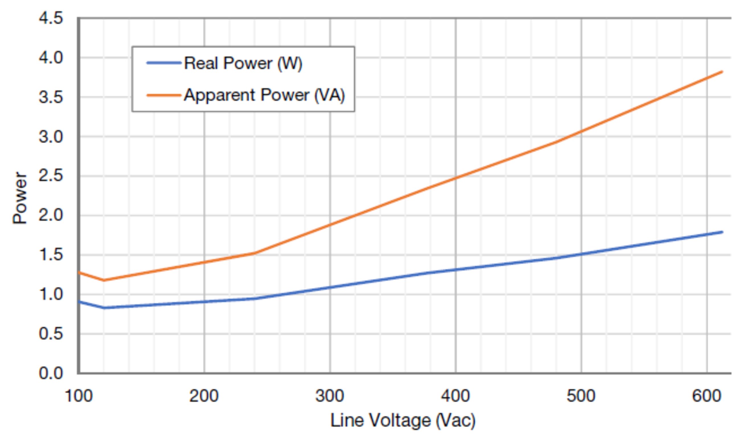
Power Consumption:
Operating Frequencies: 50 / 60 Hz
Measurement Category: CAT III
Measurement category III is for measurements performed in the building installation. Examples are measurements on distribution boards, circuit breakers, wiring, including cables, bus bars, junction boxes, switches, socket outlets in the fixed installation, and equipment for industrial use and some other equipment, for example, stationary motors with permanent connection to the fixed installation.
The line voltage measurement terminals on the meter are rated for the following CAT III voltages (these ratings appear on the front label):
Meter Service Type | CAT III Voltage Rating |
|---|---|
WR | 600 |
Current Transformer Inputs:
Nominal Input Voltage (At CT Rated Current): 0.33333 Vac RMS
Absolute Maximum Input Voltage: 5.0 Vac RMS
Input Impedance at 50/60 Hz: 23 k Ohm
Operating Temperature: -40° C to +80° C (-40° F to 176° F)
Altitude: Up to 3000 m (9842 ft)
Operating Humidity: non-condensing, 5 to 90% relative humidity (RH) up to 40°C, decreasing linearly to 50% RH at 55°C
Pollution: POLLUTION DEGREE 2 - Normally only non-conductive pollution; occasionally, a temporary conductivity caused by condensation must be expected.
Indoor Use: Suitable for indoor use
Outdoor Use: Suitable for outdoor use if mounted inside an electrical enclosure (Hammond Mfg., Type EJ Series) rated NEMA 3R or 4 (IP 66).
Detailed warranty conditions specific to your country can be found at https://www.fronius.com/en/download-center?searchword=Warranty+conditions .
If there is a warranty for the relevant product, register the product at https://warranty.fronius.com/ and activate or extend the warranty.