Introduction
Introduction
Open Platform Communications Unified Architecture (OPC UA) is a platform independent service-oriented architecture that integrates the functionality of the individual OPC classic specifications into one extensible framework.
It was developed by the OPC Foundation and first released in 2008.
OPC UA differs significantly from its predecessor OPC and was designed to support the needs of industrial automation.
This document describes the implementation of the OPC UA server within the FRONIUS TPS/i, iWave and WeldCube Connector.
What is OPC UA and what is it used for
OPC UA is one of the most used communication protocols for industrial automation. It is a platform-independent and service-oriented architecture specification that integrates all functionality from the existing OPC Classic specifications, providing a migration path to a more secure and scalable solution. The specification is backwards compatible with OPC Classic. It is designed for machine-to-machine communications.
The implementation of OPC UA server in FRONIUS TPS/i welding machines and WeldCube Connector is based on the open-source project open62541 (https://www.open62541.org) for OPC UA server and is licensed under the Mozilla Public License v2.0.
- Development for industrial communication, data collection and control
- Open source freely available and implementation under GPL 2.0 license
- Service-oriented architecture (SOA)
- State-of-the-art security concept
- Cross-platform available
- Server: an OPC UA server (e.g. welding machine) provides data
- Client: an OPC UA client (e.g. MES connector) requests or writes data from the server
- Object: nodes are organized in objects (see chapter Description of Objects and Nodes)
- Node: data node for data access (DA) read and write (see chapter Description of Objects and Nodes)
Communication Protocol
Fronius TPS/i, iWave and WeldCube Connector are using a TCP-based binary communication over opc.tcp (TCP port 4840) as this implementation is fast, reliable, secure and optimized for embedded devices.
Web-Access via http or https (SOAP) and XML web services are not implemented.
Disclamer
Although OPC UA is know as reliable and depending on the implementation as fast, the use of OPC UA with FRONIUS welding machines is only for documentation, visualization and informative purposes.
It is not allowed to use any status information provided by this communication for safety implementations.
Description of Objects and Nodes
Description of Objects and Nodes
OPC UA is organized in structured topics. All topics contain one or more nodes for data access (DA).
This chapter describes the implemented topics and nodes including data types and enumeration values.
The following objects and nodes are available from firmware version or higher:
TPS/i and iWave | 4.3.0 |
WeldCube Connector | 1.3.0 |
Objects and Nodes for TPS/i and iWave
ACTUAL
The following nodes are available during the welding process with the minimum sampling interval of 0.1 seconds. The values can be used to record the weld process data.
All nodes of ACTUAL are read-only.
Topic | Type | Unit | Description |
|---|---|---|---|
ACTUAL_CURRENT | Float [-5000.0 ... 5000.0] | [A] | Current |
ACTUAL_VOLTAGE | Float [-500.0 ... 500.0] | [V] | Voltage |
ACTUAL_WFS | Float [-99.9 ... 99.9] | [m/min] | Wire feed speed |
ACTUAL_POWER | Float [-0.000 ... 1000000.000] | [W] | Power |
ACTUAL_WELDINGTIME | Float [0.0 ... 1000000.0] | [s] | Welding time |
ACTUAL_ GASFLOW | Float [0.0 ... 100.0] / 1.8e+35 [INVALID] | [l/min] | Gasflow |
WIREBUFFER_VALUE | Float [-100 ... 100] / 1.8e+35 [INVALID] | [%] | Status of wire buffer Full: 100% |
The following topics can be used for external displays and other visualization. The values for current, voltage, wire feed speed, power and energy are automatically set to the state of the welding process.
Topic | Type | Unit | Description |
|---|---|---|---|
DISPLAY_STATUS | Enumeration (String) | N/A | Status of weld |
DISPLAY_CURRENT | Float [-5000.0 ... 5000.0] | [A] | Current |
DISPLAY_VOLTAGE | Float [-500.0 ... 500.0] | [V] | Voltage |
DISPLAY_WFS | Float [-99.9 ... 99.9] | [m/min] | Wire feed speed |
DISPLAY_POWER | Float [0.000 ... 1000000.000] | [kW] | Power |
DISPLAY_ENERGY | Float [0.000 ... 0.999] | [kJ] | Energy |
JOB
The JOB nodes are related to jobs and represent the actual state and number. For details on the specific settings of the selected job refer to SETTINGS on page (→) in Objects and Nodes for TPS/i. The nodes of JOB are writeable.
Topic | Type | Unit | Description |
|---|---|---|---|
JOBNUMBER | UInt16 [1 ... 1000] | N/A | Job number |
JOBMODE | Boolean | N/A | Job mode |
JOBREVISION | UInt16 [0 ... 65535] | N/A | Job revision |
JOBSLOPE | Float [0.0 ... 10.0] | [s] | Job slope |
JOBNAME | String [30] | N/A | Job name |
NOTE: If “JOBMODE” is “FALSE” the “JOBNUMBER” is not representative.
SYSTEM
The SYSTEM nodes represent the actual system state of welding machine including machine serial number, hour meters and information on the cooler if there is one installed. The values are published on change or update. SYSTEM nodes are read-only.
Topic | Type | Unit | Description |
|---|---|---|---|
SERIALNUMBER | String [100] | N/A | Machine serial number |
APIVERSION | String [100] | N/A | OPC UA API version |
FIRMWAREVERSION | String [100] | N/A | Firmware version of welding machine |
TOTAL_CURRENTFLOWTIME | Float [0.0 ... 1000000.0] | [h] | Hour-meter current flow time |
TOTAL_POWERONTIME | Float [0.0 ... 1000000.0] | [h] | Hour-meter power on time of machine |
TOTAL_WIRELENGTH | Float [0.0 ... 1000000.0] | [m] | Total wire length consumption |
TOTAL_SHIELDING_GAS | Float [0.0 ... 1000000.0] | [l] | Total shielding gas consumption |
COOLER_MODE | Enumeration (String) | N/A | Cooler mode |
COOLER_TEMP | Float [-200.0 ... 200.0] / | [°C] | Cooler temperature |
COOLER_FLOW | Float [-100.00 ... 100.00] / | [l/min] | Cooling circuit flow rate |
MOTOR_FORCE_M1 | Float [0 ... 999] / | [N] | Motor Force (Motor 1) |
MOTOR_FORCE_M2 | Float [0 ... 999] / | [N] | Motor Force (Motor 2) |
MOTOR_FORCE_M3 | Float [0 ... 999] / | [N] | Motor Force (Motor 3) |
PROCESS
The PROCESS nodes represent the status of the actual process. All nodes of PROCESS are read-only.
Topic | Type | Unit | Description |
|---|---|---|---|
PROCESS_ACTIVE | Boolean | N/A | Process active |
PROCESS_MAINPHASE | Boolean | N/A | Process main phase |
CURRENTFLOW | Boolean | N/A | Current flow |
ARCSTABLE | Boolean | N/A | Arc stable |
ERROR 1) | UInt16 [0 ... 65535] | N/A | Welding error |
SAFETY_STATUS | Enumeration (String) | N/A | Safety Status |
PENETRATION_STABILIZER_STATUS | Enumeration (String) | N/A | Status of penetration stabilizer |
ARC_LENGTH_STABILIZER_STATUS | Enumeration (String) | N/A | Status of arc length stabilizer |
WIREEND_VALUE | Enumeration (String) | N/A | Wire end status |
WIRE_END_VALUE_DRUM | Enumeration (String) | N/A | Wire end status of drum sensor |
WIRE_END_VALUE_RINGSENSOR | Enumeration (String) | N/A | Wire end status of ring sensor |
SELECTED_PROCESSLINE | UInt16 [0 ... 3] | N/A | 0 = TIG |
1) The signal shows the current error number of the welding device. The meaning of the error is described in the file Errorlist_TPSi_Vx.x.x and sent with each firmware release bundle PW_FW_ReleaseBundle_Official_TPSi_iWave_Vx.x.x.
TRACE
The TRACE nodes represent the traceability parameters for the actual or next weld. All nodes for TRACE are writeable at anytime. Please ensure to set those parameters before starting the weld process.
Topic | Type | Unit | Description |
|---|---|---|---|
PARTITEMNUMBER | String [100] | N/A | Item/Article number of part |
PARTSERIALNUMBER | String [100] | N/A | Serial number of part |
SEAMNUMBER | UInt16 [0 ... 65535] | N/A | Seam number (or processing step) |
PARVERSION | String [100] | N/A | Version of part |
NOTE: To set the traceability parameter use the FRONIUS Data Channel (TCP) and/or robot interface.
SETTINGS
The SETTINGS topics represent the actual welding parameter settings including welding mode and trigger mode. If not using job mode those nodes are writeable.
Topic | Type | Unit | Description |
|---|---|---|---|
WELDING_MODE | Enumeration (String) | N/A | Welding mode |
TRIGGER_MODE | Enumeration (String) | N/A | Trigger mode |
CURRENT_RECOMMVALUE | Float [-5000 ... 5000] | [A] | Current recommend value |
VOLTAGE_RECOMMVALUE | Float [-500.0 ... 500.0] | [V] | Voltage recommend value |
WFS_COMMANDVALUE | Float [0.0 ... 100.0] | [m/min] | Wire feed speed command value |
START_ARCLENGTH_CORRECTION | Float [-10.0 ... 10.0] / | N/A | Start arc length correction |
END_ARCLENGTH_CORRECTION | Float [-10.0 ... 10.0] / | N/A | End arc length correction |
START_CURRENT_TIME | Float [0.0 ... 10.0] / | [s] | Start current time |
END_CURRENT_TIME | Float [0.0 ... 10.0] / | [s] | End current time |
START_CURRENT | UInt16 [0 ... 200] | [%] | Start current |
END_CURRENT | UInt16 [0 ... 200] | [%] | End current |
GASPREFLOW | Float [0.0 ... 9.9] | [s] | Gas preflow |
GASPOSTFLOW | Float [0.0 ... 60.0] | [s] | Gas postflow |
ARCLENGTH_CORRECTION | Float [-10.0 ... 10.0] | N/A | Arc length correction |
PULSEDYNAMIC_CORRECTION | Float [-10.0 ... 10.0] | N/A | Pulse dynamic correction |
PENETRATION_STABILIZER | Float [-10.0 ... 10.0] | [m/min] | Penetration stabilizer |
ARC_LENGTH_STABILIZER | Float [0.0 ... 5.0] | N/A | Arc length stabilizer |
SLOPE_1 | Float [0.0 ... 9.9] | [s] | Slope 1 |
SLOPE_2 | Float [0.0 ... 9.9] | [s] | Slope 2 |
GASVALUE | Float [0.5 ... 30.0] / | [l/min] | Gas command value (or “AUTO”) |
GASFACTOR | Float [0.90 ... 20.0] | N/A | Gas factor |
SFI | Boolean | N/A | SFI |
SFI_HOTSTART | Float [0.00 ... 2.00] / | [s] | SFI hot start |
SYNCHROPULSE_ENABLE | Boolean | N/A | Synchropulse: Enable |
SYNCHROPULSE_FREQUENCY | Float [0.5 ... 10.0] | [Hz] | Synchropulse: Frequency |
SYNCHROPULSE_DELTA_FEEDER | Float [0.1 ... 6.0] | [m/min] | Synchropulse: Delta feeder |
SYNCHROPULSE_DUTYCYCLE | Float [10 ... 90] | [%] | Synchropulse: Duty cycle |
SYNCHROPULSE_ARCLENGTH_ | Float [-10.0 ... 10.0] | N/A | Synchropulse: Arc length correction high |
SYNCHROPULSE_ARCLENGTH_ | Float [-10.0 ... 10.0] | N/A | Synchropulse: Arc length correction low |
CW_CURRENT_COMMANDVALUE | Float [0 ... 500] | [A] | Coldwire current command value |
CW_FEEDER_COMMANDVALUE | Float [0.0 ... 100.0] | [m/min] | Coldwire wire feed speed command value |
CYCLETIG_ENABLE | Boolean | N/A | CycleTIG enable |
CYCLETIG_INTERVAL_CYCLES | UInt16 [0 ... 2000] / | N/A | Number of cycles until process ends |
CYCLETIG_INTERVAL_PAUSETIME | Float [0.02 ... 2.0] | [s] | Pause between impulse |
CYCLETIG_INTERVAL_TIME | Float [0.02 ... 2.0] | [s] | Duration of impulse |
TIG_AC_CURRENT_OFFSET | Float [-70 ... 70] | [%] | TIG AC current offset |
TIG_AC_FREQUENCY | UInt16 [40 ...250] / | [Hz] | TIG AC frequency |
TIG_AC_WAVEFORM_NEGATIVE | Enumeration (String) | N/A | TIG AC waveform of negative curve |
TIG_AC_WAVEFORM_POSITIVE | Enumeration (String) | N/A | TIG AC waveform of positive curve |
TIG_BALANCE | Float [15.0 ... 50.0] | [%] | Balance in TIG AC mode |
TIG_CALOTTE_MODE | Enumeration (String) | N/A | TIG AC calotte mode |
TIG_DOWN_SLOPE | Float [0.01 ... 30.0] / | [s] | TIG down slope time |
TIG_DROP_CURRENT_SLOPE1 | Float [0.01 ... 30.0] / | [s] | Slope time from main current to drop current |
TIG_DROP_CURRENT_SLOPE2 | Float [0.01 ... 30.0] / | [s] | Slope time from drop current to main current |
TIG_ELECTRODE_DIAMETER | Float [1.0 ... 6.4] / | [mm] | TIG electrode diameter |
TIG_END_CURRENT | UInt16 [0 ... 100] | [%] | End current in % of main current |
TIG_END_CURRENT_TIME | Float [0.01 ... 30.0] / | [s] | Duration of end phase |
TIG_EXT_CSS | Float [0.1 ... 10.0] / | [V] | TIG extended comfort stop |
TIG_EXT_UCUTOFF | Float [6.0 ... 90.0] / | [V] | TIG extended cut off voltage |
TIG_GASPREFLOW | Float [0.0 ... 9.9] | [s] | TIG gas preflow time |
TIG_HF_IGNITION | Enumeration (String) | N/A | High frequency start |
TIG_HF_IGNITION_DELAY | Float [0.1 ... 5.0] | [s] | Delay of HF impulse |
TIG_I1 | Float [0 ... 5000] | [A] | TIG main current |
TIG_IGNITION_TIMEOUT | Float [0.1 ... 9.9] | [s] | Ignition timeout |
TIG_POLARITY | Enumeration (String) | N/A | TIG polarity |
TIG_PULSE_BACKROUND_CURRENT | Float [0 ... 100] | [%] | Base current in % of main current at TIG pulse |
TIG_PULSE_DUTY_CYCLE | Float [10 ... 90] | [%] | Pulse pause ratio |
TIG_PULSE_FREQUENCY | Float [0.2 ... 1000.0] / | [Hz] | Pulse frequency TIG DC |
TIG_RPI | Enumeration (String) | N/A | Reserve polarity ignition |
TIG_SHIELDING_1_GASFACTOR | Float [0.9 ... 20.0] / | N/A | Shielding gas 1 factor |
TIG_SHIELDING_1_GASVALUE | Float [0.5 ... 30.0] | [l/min] | Shielding gas 1 |
TIG_SPOT_TIME | Float [0.02 ... 120] | [s] | Main phase time in spot trigger mode |
TIG_START_CURRENT | Float [0 ... 200] | [%] | Start current in % of main current |
TIG_START_CURRENT_TIME | Float [0.01 ... 30.0] / | [s] | Duration of starting phase |
TIG_TAC | Float [0.1 ... 9.9] / | [s] | TAC time or OFF/ON |
TIG_TRIGGER_MODE | Enumeration (String) | N/A | TIG trigger mode |
TIG_UP_SLOPE | Float [0.01 ... 30.0] / | [s] | UP slope time |
TIG_WAVEFORM_BACKGROUND | Enumeration (String) | N/A | TIG DC waveform of base current |
TIG_WAVEFORM_PULSE | Enumeration (String) | N/A | TIG DC waveform of pulse |
TIG_WIRE_CORRECTION | Float [-10.0 ... 10.0] / | N/A | Wire correction in TIG-Dynamic Wire Mode |
TIG_WORKING_2_GASFACTOR | Float [0.9 ... 20.0] / | N/A | Working gas 2 factor |
TIG_WORKING_2_GASVALUE | Float [0.5 ... 30.0] | [l/min] | Working gas 2 |
Objects and Nodes for WeldCube Connector
ACTUAL
The following nodes are available during the welding process with the minimum sampling interval of 0.1 seconds. The values can be used to record the weld process data. All nodes of ACTUAL are read-only. Wire feed speed is only available for WeldCube Connector U/I/WFS.
Topic | Type | Unit | Description |
|---|---|---|---|
ACTUAL_CURRENT | Float [-5000.0 ... 5000.0] | [A] | Current |
ACTUAL_VOLTAGE | Float [-500.0 ... 500.0] | [V] | Voltage |
ACTUAL_WFS | Float [-99.9 ... 99.9] | [m/min] | Wire feed speed |
ACTUAL_POWER | Float [-0.000 ... 1000000.000] | [W] | Power |
ACTUAL_WELDINGTIME | Float [0.0 ... 1000000.0] | [s] | Welding time |
SYSTEM
The SYSTEM nodes represent the actual system state of welding machine including machine serial number, hour meters and information on the cooler if there is one installed. The values are published on change or update. SYSTEM nodes are read-only. TOTAL_WIRELENGTH is only available for WeldCube Connector U/I/WFS.
Topic | Type | Unit | Description |
|---|---|---|---|
SERIALNUMBER | String [100] | N/A | Machine serial number |
APIVERSION | String [100] | N/A | OPC UA API version |
FIRMWAREVERSION | String [100] | N/A | Firmware version of welding machine |
TOTAL_CURRENTFLOWTIME | Float [0.0 ... 1000000.0] | [h] | Hour-meter current flow time |
TOTAL_POWERONTIME | Float [0.0 ... 1000000.0] | [h] | Hour-meter power on time of machine |
TOTAL_WIRELENGTH | Float [0.0 ... 1000000.0] | [m] | Total wire length consumption |
PROCESS
The PROCESS nodes represent the status of the actual process. All nodes of PROCESS are read-only.
Topic | Type | Unit | Description |
|---|---|---|---|
PROCESS_ACTIVE | Boolean | N/A | Process active |
CURRENTFLOW | Boolean | N/A | Current flow |
ERROR 1) | UInt16 [0 ... 65535] | N/A | Welding error |
SAFETY_STATUS | Enumeration (String) | N/A | Safety status |
1) The signal shows the current error number of the welding device. The meaning of the error is described in the file Errorlist_TPSi_Vx.x.x and sent with each firmware release bundle PW_FW_ReleaseBundle_Official_TPSi_iWave_Vx.x.x.
TRACE
The TRACE nodes represent the traceability parameters for the actual or next weld. All nodes for TRACE are writeable at anytime. Please ensure to set those parameters before starting the weld process.
Topic | Type | Unit | Description |
|---|---|---|---|
PARTITEMNUMBER | String [100] | N/A | Item/Article number of part |
PARTSERIALNUMBER | String [100] | N/A | Serial number of part |
SEAMNUMBER | UInt16 [0 ... 65535] | N/A | Seam number (or processing step) |
PARVERSION | String [100] | N/A | Version of part |
NOTE: To set the traceability parameter use the FRONIUS Data Channel (TCP) and/or robot interface.
Setup and Installation
Setup and Installation
The configuration page for OPC UA setup is located in the SmartManager (welding system website) under the topic “Power Source Settings”.
NOTE: The settings for OPC UA are not affected on backup and restore of FRONIUS welding machines.
- Enable/Disable: Enable or disable OPC UA server
- Security policy: Select security policy
- Server certificate: Upload server certificate
- Server private key: Upload server private key
- None: Do not use username/password for authentication
- Username: Username for authentication
- Password: Password for authentication
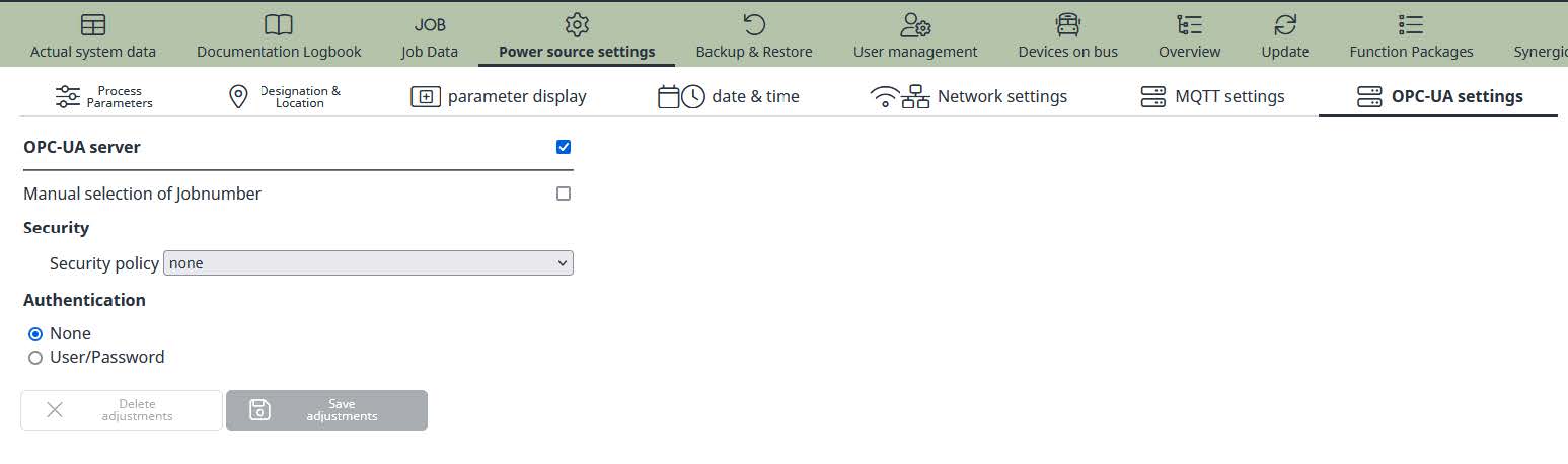
Enable/Disable OPC UA Server
By using the enable/disable flag of the checkbox the OPC UA server for the welding machine can be enable or disable in general.
Disabling the server will break all open connections to the welding machine.
Security Settings
Without any authentication and certificated OPC UA will work in anonymous mode. By using username and password the access on the objects can be restricted. To encrypt the communication between server and client you can use a server certificate and a server private key.
The security policy can be set to:- None
- Basic128RSA15 (deprecated)
- Basic256SHA256
It is not recommended to use authentication by username and password without encryption. No authentication and no encryption should only be used in experimental stage.
Basic128RSA15 encryption uses a SHA1 algorithm which is not state of the art anymore. This encryption algorithm should not be used anymore and will be removed in a future update.
Sampling Rate
For actual values for current, voltage, wire feeder speed (wfs) and power it is possible to setup the sampling rate for publishing. The sampling rate can be set from 0.1 to 100 seconds.
NOTE: If you use job mode for welding, the sampling rate defined in the selected job is used for publishing the values. Ensure that the required sampling rate is set correctly in each job upon your needs.
This sampling rate affects the update of the ACTUAL nodes on the server. Using a higher sampling rate by the OPC UA client will not deliver more updated values. Ensure that the sampling rate within the machine and/or job matches the rate of your client.
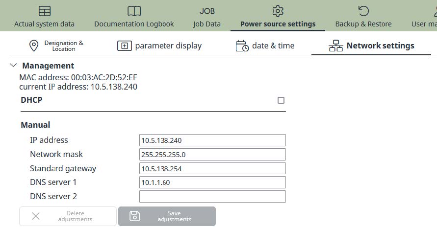
Network Settings
To ensure proper function of OPC UA communication it is necessary to setup the TCP/IP parameters according to your network policy. It is recommended to use a static IP address or DHCP reservation.
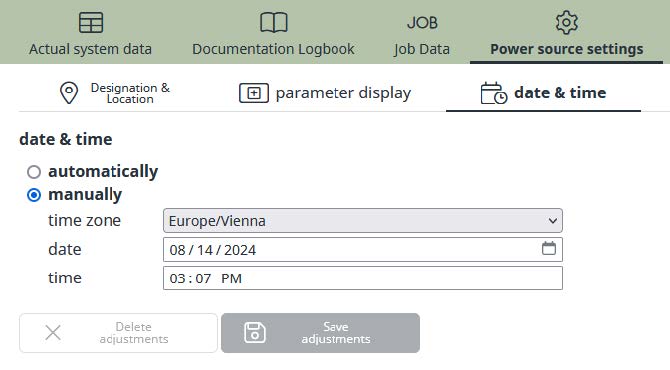
Time Server Settings (NTP)
For all documentation purposes within the FRONIUS welding data product family it is recommended to synchronize date and time with a local or global time server.
Examples and Best Practice
Examples and Best Practice
This chapter includes and examples and best practice information on using OPC UA with FRONIUS welding machines.
Examples and Best Practice
This chapter includes and examples and best practice information on using OPC UA with FRONIUS welding machines.
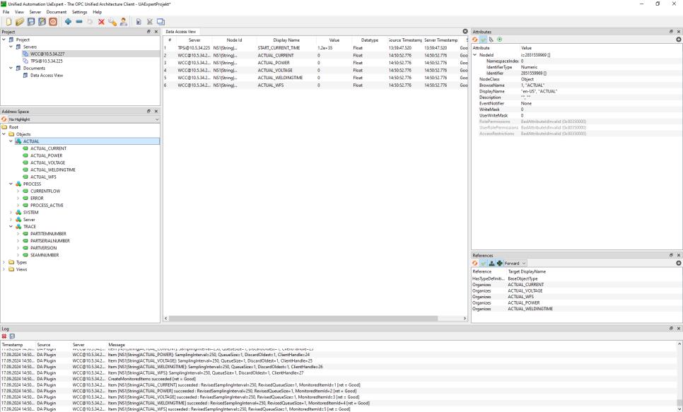
Getting started with UaExpert Client
The easiest way to start with OPC UA on FRONIUS welding machines is to use UaExpert Client by Unified Automation GmbH.
The following instruction will guide you through the first steps by using Microsoft Windows® and default settings in anonymous mode.
STEP 1- Register and download UaExpert Client from https://www.unifiedautomation.com
- Install the software on your computer
- Setup your firewall to allow TCP port 4840 for outgoing traffic
- Connect your FRONIUS welding machine to your network
- Enable OPC UA on your FRONIUS welding machine by using the SmartManager
- Select encryption “none”
- Start the UaExpert Client
- Select “SERVER” and add a new connection
- Double click on “Add Server” and enter the IP address or host name of the FRONIUS welding machine
- Open the TreeView and select “Discovered Device” and press “OK”
- Select your server and connect the address space will update automatically all objects and nodes
- Per drag and drop you can select the nodes you want to view or write