
Fronius LogoFronius Mobile Logo
en
      Operating InstructionsRobacta PTW 500, 1500, 3500
    • General
      • Machine concept
      • Applications
      • Scope of supply - Robacta PTW 500
      • Scope of supply - Robacta PTW 1500
      • Scope of supply - Robacta PTW 3500
      • PTW 500 options
      • PTW 1500 options
      • PTW 3500 options
    • Assembling the Robacta PTW 500, 1500, 3500
      • Safety
      • Assembling the Robacta PTW 500
      • Assembling the Robacta PTW 1500
      • Assembling the Robacta PTW 3500
    • Adjusting the tungsten electrode
      • Safety
      • General
      • Adjusting the PTW 500 tungsten electrode
      • Calibrating the PTW 1500 adjusting gauge
      • Adjusting the PTW 1500 tungsten electrode
      • Adjusting the PTW 3500 tungsten electrode
    • Start-up
      • Safety
      • Proper use
      • Start-up
    • Loading limits dependent on the plasma gas flow rate
      • General
      • Loading limits dependent on the plasma gas flow rate
      • Loading limit example (PTW 1500)
    • Troubleshooting
      • Safety
      • Troubleshooting
    • Care, maintenance and disposal
      • Safety
      • Plasma welding torch maintenance
      • Maintenance activities with each start-up of the plasma welding torch
      • Monthly
      • Disposal
    • Technical data
      • PTW 500
      • PTW 1500, PTW 3500
    • 011-09042026

    Robacta PTW 500, 1500, 3500

    download
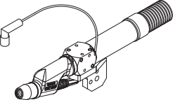
    Machine concept
    Assembling
    Adjusting the tungsten electrode
    Start-up
    Technical data
    Spare parts
    ContactImprintTerms and ConditionsData privacy statement
    © 2026 Fronius International GmbH
    © 2026 Fronius International GmbH
    ContactImprintTerms and ConditionsData privacy statement

    General

    link_horizontalLink copied

    Machine concept

    The water-cooled plasma robot welding torch is designed for plasma welding and plasma brazing of materials up to a thickness of 1.5 mm (PTW 500), 3 mm (PTW 1500) and 8 mm (PTW 3500).
    The welding torches have a Fronius F++ connection as standard. Various adapters are available to enable the torches to be operated with any standard plasma device. Each torch can be equipped with KD Drive, a pushed wire-feed unit or a drag gas nozzle.
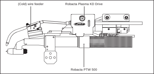
    Robacta PTW 500 with Robacta Plasma KD Drive and wirefeed options Robacta PTW
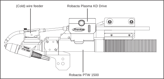
    Robacta PTW 1500 with Robacta Plasma KD Drive and wirefeed options
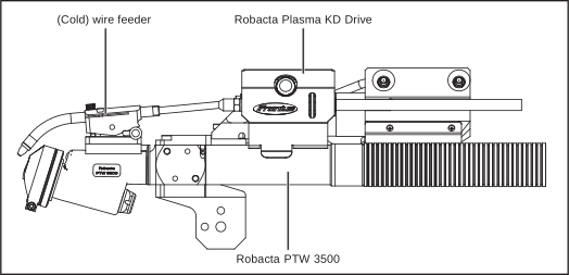
    Robacta PTW 3500 with Robacta Plasma KD Drive and wirefeed options
    1. General

    Machine concept

    link_horizontalLink copied

    The water-cooled plasma robot welding torch is designed for plasma welding and plasma brazing of materials up to a thickness of 1.5 mm (PTW 500), 3 mm (PTW 1500) and 8 mm (PTW 3500).
    The welding torches have a Fronius F++ connection as standard. Various adapters are available to enable the torches to be operated with any standard plasma device. Each torch can be equipped with KD Drive, a pushed wire-feed unit or a drag gas nozzle.
    Robacta PTW 500 with Robacta Plasma KD Drive and wirefeed options Robacta PTW
    Robacta PTW 1500 with Robacta Plasma KD Drive and wirefeed options
    Robacta PTW 3500 with Robacta Plasma KD Drive and wirefeed options
    1. General

    Applications

    link_horizontalLink copied

    The plasma robot welding torch is used in automated applications, e.g.:
    • Pipeline and equipment construction
    • Container construction
    • Applications requiring the highest quality standards
    • Applications using special materials (e.g. titanium, nickel-based alloys)
    1. General

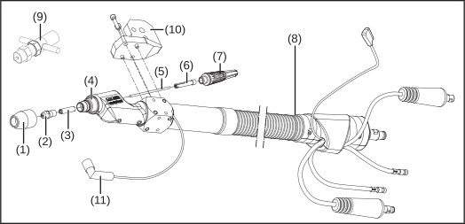
    Scope of supply - Robacta PTW 500

    link_horizontalLink copied
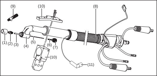
    (1)
    Shielding gas nozzle
    (2)
    Plasma nozzle 1.2 mm
    (3)
    Ceramic gas nozzle
    (4)
    Torch body with stop ring
    (5)
    Tungsten electrode 1.0 mm
    (6)
    Clamping sleeve 1.0 mm


    (7)
    Torch cap
    (8)
    Hosepack 4 m, Fronius F++ / FG connection
    (9)
    Adjusting gauge
    (10)
    Holder
    (11)
    Connection for cut-out box
    1. General

    Scope of supply - Robacta PTW 1500

    link_horizontalLink copied
    (1)
    Shielding gas nozzle
    (2)
    Plasma nozzle 2.5 mm
    (3)
    Ceramic centring tube
    (4)
    Torch body with stop ring
    (5)
    Tungsten electrode WL 15, 2.4 mm
    (6)
    Clamping sleeve 2.4 mm


    (7)
    Robacta PTW 1500 torch cap
    (8)
    Hosepack 4 m, Fronius F++ connection
    (9)
    Adjusting gauge 2,5 - 3 mm
    (10)
    Holder
    (11)
    Connection for cut-out box
    1. General

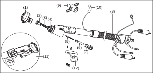
    Scope of supply - Robacta PTW 3500

    link_horizontalLink copied
    (1)
    Shielding gas nozzle
    (2)
    Plasma nozzle 3.2 mm
    (3)
    Ceramic centring tube
    (4)
    Torch body with stop ring
    (5)
    Tungsten electrode WL 15, 4.8 mm
    (6)
    Clamping sleeve 4.8 mm


    (7)
    Robacta PTW 3500 torch cap
    (8)
    Hosepack 4 m, Fronius F++ / FG connection
    (9)
    Adjusting gauge
    (10)
    Connection for cut-out box
    (11)
    Water stopper
    (12)
    Holder
    1. General

    PTW 500 options

    link_horizontalLink copied
    • Hot wire option
    • Plasma nozzle 0.6 / 0.8 / 1.0 / 1.4 / 1.6 mm
    • Adapter for the non-digital PlasmaModul
    • Cold wire feeder with drive (push-pull system): Robacta Plasma KD Drive
    • Cold wire feeder (push system): Robacta Plasma KD
    • Drag gas nozzle 50 / 100 mm
    1. General

    PTW 1500 options

    link_horizontalLink copied
    • Adjusting gauge ∅ 1.5 - 2 mm
    • Cold wire feeder with drive (push-pull system): Robacta Plasma KD Drive
    • Cold wire feeder (push system): Robacta Plasma KD
    • Hot wire option
    • Plasma nozzle 1.0 / 1.5 / 2 / 3 mm; 2.0 x 29 mm long
    • Ceramic centring tube 1.6 / 3.2 mm
    • Clamping sleeve 1.6 / 3.2 mm
    • Adapter for the non-digital PlasmaModul
    • Drag gas nozzle 50 / 100 mm
    1. General

    PTW 3500 options

    link_horizontalLink copied
    • Cold wire feeder with drive (push-pull system): Robacta Plasma KD Drive
    • Cold wire feeder (push system): Robacta Plasma KD
    • Hot wire option
    • Plasma nozzle 2.0 / 2.5 / 3.5 / 4.0 mm
    • Plasma nozzle 2.0 / 2.5 / 3.2 / 3.5 / 4.0 mm with 4 x 1 mm balance holes
    • Conical plasma nozzle
    • Ceramic centring tube 6.4 mm
    • Clamping sleeve 6.4 mm
    • Adapter for the non-digital PlasmaModul
    • Drag gas nozzle 50 / 100 mm
    • Ceramic gas nozzle + appropriate stop ring

    Assembling the Robacta PTW 500, 1500, 3500

    link_horizontalLink copied

    Safety

    WARNING!

    Danger from incorrect operation and work that is not carried out properly.

    This can result in serious personal injury and damage to property.

    All the work and functions described in this document must only be carried out by technically trained and qualified personnel.

    Read and understand this document in full.

    Read and understand all safety rules and user documentation for this device and all system components.
    1. Assembling the Robacta PTW 500, 1500, 3500

    Safety

    link_horizontalLink copied

    WARNING!

    Danger from incorrect operation and work that is not carried out properly.

    This can result in serious personal injury and damage to property.

    All the work and functions described in this document must only be carried out by technically trained and qualified personnel.

    Read and understand this document in full.

    Read and understand all safety rules and user documentation for this device and all system components.

    1. Assembling the Robacta PTW 500, 1500, 3500

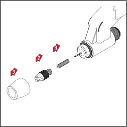
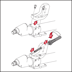
    Assembling the Robacta PTW 500

    link_horizontalLink copied
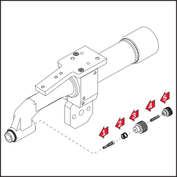
    1
    Insert clamping sleeve
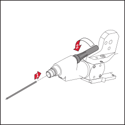
    2
    Insert tungsten electrode

    IMPORTANT! Insert the tungsten electrode so that the tip protrudes approx. 10 mm out of the torch body. Slightly tighten the torch cap so that the tungsten electrode can still move inside the torch body.
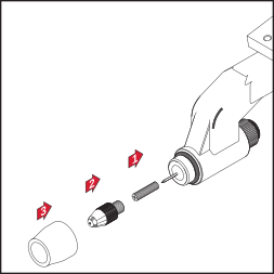
    3
    Assemble centring tube, plasma nozzle and shielding gas nozzle

    IMPORTANT! Check that the tungsten electrode is adjusted correctly (see „Adjusting the tungsten electrode.
    1. Assembling the Robacta PTW 500, 1500, 3500

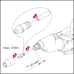
    Assembling the Robacta PTW 1500

    link_horizontalLink copied
    1
    Fit holder, insert clamping sleeve
    2
    Insert tungsten electrode

    IMPORTANT! Insert the tungsten electrode so that the tip protrudes approx. 10 mm out of the torch body. Slightly tighten the torch cap so that the tungsten electrode can still move inside the torch body.
    3
    Assemble centring tube, plasma nozzle and shielding gas nozzle

    IMPORTANT! Check that the tungsten electrode is adjusted correctly (see „Adjusting the tungsten electrode“)
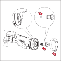
    1. Assembling the Robacta PTW 500, 1500, 3500

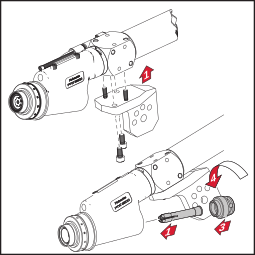
    Assembling the Robacta PTW 3500

    link_horizontalLink copied
    1
    Fit holder, insert clamping sleeve
    2
    Insert tungsten electrode

    IMPORTANT! Insert the tungsten electrode so that the tip protrudes approx. 10 mm out of the torch body. Slightly tighten the torch cap so that the tungsten electrode can still move inside the torch body.
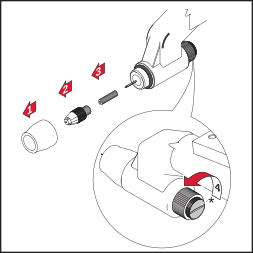
    3
    Assemble centring tube, plasma nozzle and shielding gas nozzle

    Water-cooled protective gas nozzles must be connected to the water connections.
    Ceramic protective gas nozzles do not need any water cooling. If ceramic protective gas nozzles are being used, the two water connections must be joined together using the water stopper.

    IMPORTANT! Check that the tungsten electrode is adjusted correctly (see „Adjusting the tungsten electrode“)

    Adjusting the tungsten electrode

    link_horizontalLink copied

    Safety

    WARNING!

    Danger from incorrect operation and work that is not carried out properly.

    This can result in serious personal injury and damage to property.

    All the work and functions described in this document must only be carried out by technically trained and qualified personnel.

    Read and understand this document in full.

    Read and understand all safety rules and user documentation for this device and all system components.

    1. Adjusting the tungsten electrode

    Safety

    link_horizontalLink copied

    WARNING!

    Danger from incorrect operation and work that is not carried out properly.

    This can result in serious personal injury and damage to property.

    All the work and functions described in this document must only be carried out by technically trained and qualified personnel.

    Read and understand this document in full.

    Read and understand all safety rules and user documentation for this device and all system components.

    1. Adjusting the tungsten electrode

    General

    link_horizontalLink copied

    Apart from the specified plasma gas flow rate, the position of the tungsten electrode plays a crucial role in determining the loading limits.

    By loading limits we mean the maximum possible welding current
    • For a particular plasma nozzle
    • For a particular plasma gas flow rate
    • For a particular tungsten electrode position

    The supplied setting gage makes it easier to position the tungsten electrode.
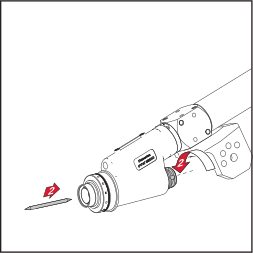
    1. Adjusting the tungsten electrode

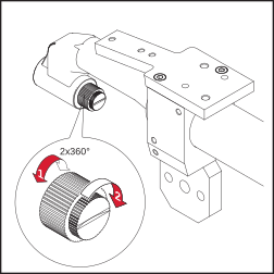
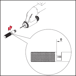
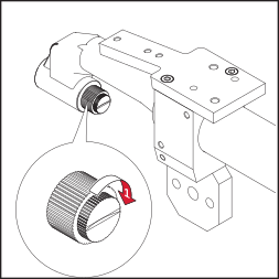
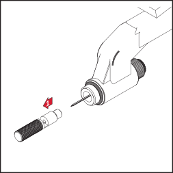
    Adjusting the PTW 500 tungsten electrode

    link_horizontalLink copied
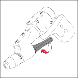
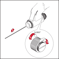
    1
    *) Loosen the torch cap - caution, the tungsten electrode may fall out of the plasma torch if the torch is in a particular position.
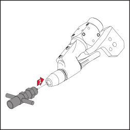
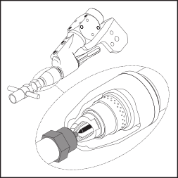
    2
    3
    ... and adjust tungsten electrode
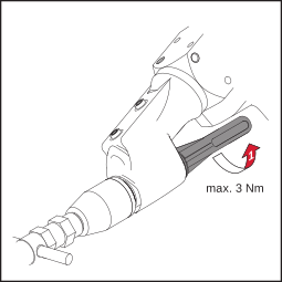
    4
    5
    6
    1. Adjusting the tungsten electrode

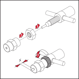
    Calibrating the PTW 1500 adjusting gauge

    link_horizontalLink copied
    Setting the adjusting gauge to measurement „x“

    IMPORTANT! The standard setting for measurement „x“ on the adjusting gauge depends on the diameter of the plasma nozzle. Refer to the following table when adjusting the standard setting for measurement „x“:

    ∅ Plasma-nozzle

    „x“

    Adjusting gauge

    1.0 mm

    -

    -

    1.5 mm

    1.5 mm

    ∅1.5 - 2 mm

    2.0 mm

    2.0 mm

    ∅1.5 - 2 mm

    2.5 mm

    2.5 mm

    ∅2.5 - 3 mm

    3.0 mm

    2.5 mm

    ∅2.5 - 3 mm

    1. Adjusting the tungsten electrode

    Adjusting the PTW 1500 tungsten electrode

    link_horizontalLink copied
    1
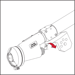
    Loosen the torch cap - caution, the tungsten electrode may fall out of the plasma torch if the torch is in a particular position.
    2
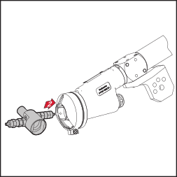
    Place adjusting gauge onto plasma nozzle ...
    3
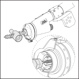
    ... and adjust tungsten electrode
    4
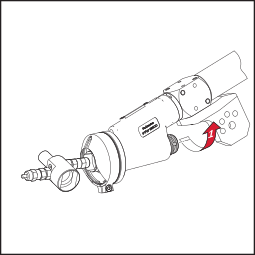
    Fix the tungsten electrode in place using the torch cap
    1. Adjusting the tungsten electrode

    Adjusting the PTW 3500 tungsten electrode

    link_horizontalLink copied
    1
    Loosen the torch cap - caution, the tungsten electrode may fall out of the plasma torch if the torch is in a particular position.
    2
    Place adjusting gauge onto plasma nozzle ...
    3
    ... and adjust tungsten electrode
    4
    Fix the tungsten electrode in place using the torch cap

    Start-up

    link_horizontalLink copied

    Safety

    WARNING!

    Danger from incorrect operation and work that is not carried out properly.

    This can result in serious personal injury and damage to property.

    All the work and functions described in this document must only be carried out by technically trained and qualified personnel.

    Read and understand this document in full.

    Read and understand all safety rules and user documentation for this device and all system components.

    1. Start-up

    Safety

    link_horizontalLink copied

    WARNING!

    Danger from incorrect operation and work that is not carried out properly.

    This can result in serious personal injury and damage to property.

    All the work and functions described in this document must only be carried out by technically trained and qualified personnel.

    Read and understand this document in full.

    Read and understand all safety rules and user documentation for this device and all system components.

    1. Start-up

    Proper use

    link_horizontalLink copied

    The plasma torch is intended exclusively for plasma welding and plasma brazing. Utilisation for any other purpose, or in any other manner, shall be deemed to be „not in accordance with the intended purpose“.

    Utilisation in accordance with the „intended purpose“ also comprises

    • following all the instructions in these operating instructions
    • carrying out all the specified inspection and servicing work
    1. Start-up

    Start-up

    link_horizontalLink copied
    1Mount plasma torch onto robot
    2Check plasma torch to see whether:
    • all parts are present
    • the parts have been correctly fitted

    NOTE!

    An incorrectly adjusted tungsten electrode can damage the plasma nozzle during commissioning. Adjust the tungsten electrode according to the plasma nozzle used and the application.
    3Adjust the tungsten electrode using the adjusting gauge
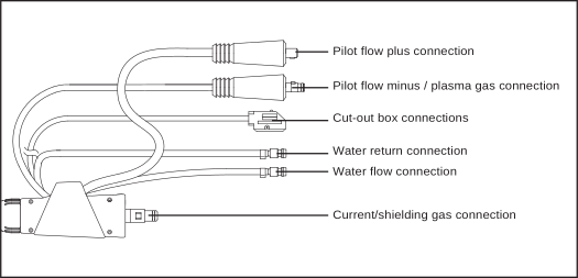
    4Connect the components of the plasma torch hosepack to the plasma device:
    • Current/shielding gas connection
    • Pilot flow cable
    • Cable for pilot flow mass/plasma gas
    • Water return hose
    • Water flow hose
    Plasma torch hosepack: connections
    5When starting up for the first time, make sure the gas flow is correct
    6Position plasma torch (adjust robot)
    7Purge shielding gas and plasma gas for at least 30 seconds

    NOTE!

    The plasma torch must be cooled constantly during operation.

    8Check that the cooling circuit on the plasma machine is functioning correctly, set the cooling unit to permanent operation (e.g. set-up menu on power source, parameter C-C =ON)

    NOTE!

    Igniting the pilot arc without presetting the plasma gas can damage the plasma nozzle, ceramic centring tube and tungsten electrode (all wearing parts).

    9Specify the plasma gas value (according to the diameter of the plasma nozzle and the application)
    10Ignite pilot arc

    IMPORTANT! To reduce wear, the pilot arc should burn throughout the operation.

    11Start welding (depending on the application)

    Loading limits dependent on the plasma gas flow rate

    link_horizontalLink copied

    General

    Loading limits for plasma welding/plasma brazing depend on the following factors:
    • Diameter of the plasma nozzle
    • Position of the tungsten electrode
    • Plasma gas flow rate

    The following loading limits apply to the standard tungsten electrode setting (see also „Adjusting the tungsten electrode“).

    1. Loading limits dependent on the plasma gas flow rate

    General

    link_horizontalLink copied
    Loading limits for plasma welding/plasma brazing depend on the following factors:
    • Diameter of the plasma nozzle
    • Position of the tungsten electrode
    • Plasma gas flow rate

    The following loading limits apply to the standard tungsten electrode setting (see also „Adjusting the tungsten electrode“).

    1. Loading limits dependent on the plasma gas flow rate

    Loading limits dependent on the plasma gas flow rate

    link_horizontalLink copied
    For plasma welding, the values for the plasma gas flow rate and maximum welding current must lie within the set limits. An upper or lower exceed of these limits can change the plasma properties, e.g.:
    • Low plasma gas flow rate -> „soft“ plasma jet
    • High plasma gas flow rate -> „hard“ plasma jet („plasma cutting“)

    IMPORTANT! Do not exceed the upper or lower limits set for plasma gas values and max. welding current during operation.

    IMPORTANT! The minimum coolant flow rate is 1 l/min

    This table is only valid for the PTW 500 (electrode diameter 1.0 mm; d.c. 60%):

    ø Plasma nozzle

    Plasma gas flow rate

    Max. welding current

    0.6 mm

    Min. 0.30 l/min

    15 A

    0.8 mm

    Min. 0.30 l/min

    20 A

    1 mm

    Min. 0.30 l/min

    28 A

    1.2 mm

    Min. 0.30 l/min

    35 A

    1.4 mm

    Min. 0.30 l/min

    45 A

    1.6 mm

    Min. 0.30 l/min

    50 A

    1.8 mm

    Min. 0.30 l/min

    50 A

    This table is only valid for the PTW 1500:

    ø Plasma nozzle

    Plasma gas flow rate

    Max. welding current

    1.5 mm

    Min. 0.30 l/min
    Max. 0.80 l/min

    60 A
    100 A

    2.0 mm

    Min. 0.35 l/min
    Max. 1.00 l/min

    80 A
    120 A

    2.5 mm

    Min. 0.45 l/min
    Max. 1.20 l/min

    110 A
    145 A

    3.0 mm

    Min. 0.55 l/min
    Max. 1.30 l/min

    130 A
    150 A

    This table is only valid for the PTW 3500 in conjunction with a FK9000 cooling unit:

    ø Plasma nozzle

    Plasma gas flow rate

    Max. welding current

    2.0 mm

    Min. 1.0 l/min

    170 A

    2.5 mm

    Min. 1.0 l/min

    190 A

    3.2 mm

    Min. 1.0 l/min

    210 A

    3.5 mm

    Min. 1.0 l/min

    225 A

    4.0 mm

    Min. 1.0 l/min

    250 A

    Table is only valid for the PTW 3500 in conjunction with a CHILLY 15 cooling unit:

    ø Plasma nozzle

    Plasma gas flow rate

    Max. welding current

    2.0 mm

    Min. 1.0 l/min

    225 A

    2.5 mm

    Min. 1.0 l/min

    250 A

    3.2 mm

    Min. 1.0 l/min

    275 A

    3.5 mm

    Min. 2.0 l/min

    300 A

    4.0 mm

    Min. 2.0 l/min

    350 A

    Minimum plasma gas flow rate:
    Amount of gas at which the welding arc still remains stable.

    IMPORTANT! Welding using a minimum plasma gas flow places a severe load on the plasma nozzle and should be avoided.

    Maximum plasma gas flow rate:
    Amount of gas that makes working with the maximum welding current possible, depending on the plasma nozzle

    Maximum welding current:
    Welding current permitted when using a particular plasma nozzle, standard tungsten electrode setting and minimum or maximum plasma gas flow rate.

    IMPORTANT! Use pure argon as plasma gas. The limit values listed above can only be obtained using pure argon.

    1. Loading limits dependent on the plasma gas flow rate

    Loading limit example (PTW 1500)

    link_horizontalLink copied

    In the case of a plasma nozzle with a diameter of 2.0 mm and a selected minimum plasma gas flow rate of 0.35 l/min, a maximum welding current of 80 A is permitted for the standard tungsten electrode setting.

    Troubleshooting

    link_horizontalLink copied

    Safety

    WARNING!

    An electric shock can be fatal.

    Before carrying out any work on the welding torch:

    Turn the mains switches of the power source and plasma device to the "0" position

    Disconnect the power source and plasma device from the mains

    Put up an easy-to-understand warning sign to stop anybody inadvertently switching them back on again

    1. Troubleshooting

    Safety

    link_horizontalLink copied

    WARNING!

    An electric shock can be fatal.

    Before carrying out any work on the welding torch:

    Turn the mains switches of the power source and plasma device to the "0" position

    Disconnect the power source and plasma device from the mains

    Put up an easy-to-understand warning sign to stop anybody inadvertently switching them back on again

    1. Troubleshooting

    Troubleshooting

    link_horizontalLink copied
    Pilot arc not igniting
    Cause:Tungsten electrode missing
    Remedy:Insert tungsten electrode
    Cause:Plasma nozzle and tungsten electrode too far apart
    Remedy:Position tungsten electrode correctly
    Cause:Plasma nozzle and tungsten electrode touching or too close (short circuit between plasma nozzle and tungsten electrode)
    Remedy:Position tungsten electrode correctly
    Copper droplets on the plasma nozzle after a short welding time
    The formation of droplets on the plasma nozzle is a sign that the plasma nozzle is badly damaged. If the temperature is too high, the plasma nozzle melts and leaks out.
    Cause:Excessive load values
    Remedy:Check current and plasma gas flow rate, change plasma nozzle, reduce load
    Excessive plasma nozzle wear
    Cause:Insufficient cooling
    Remedy:Check the current and plasma gas flow rate, check the cooling circuit, increase the plasma gas flow rate, check for wear on the nozzle connection

    Care, maintenance and disposal

    link_horizontalLink copied

    Safety

    WARNING!

    An electric shock can be fatal.

    Before carrying out any work on the welding torch:

    Turn the mains switches of the power source and plasma device to the "0" position

    Disconnect the power source and plasma device from the mains

    Put up an easy-to-understand warning sign to stop anybody inadvertently switching them back on again

    1. Care, maintenance and disposal

    Safety

    link_horizontalLink copied

    WARNING!

    An electric shock can be fatal.

    Before carrying out any work on the welding torch:

    Turn the mains switches of the power source and plasma device to the "0" position

    Disconnect the power source and plasma device from the mains

    Put up an easy-to-understand warning sign to stop anybody inadvertently switching them back on again

    1. Care, maintenance and disposal

    Plasma welding torch maintenance

    link_horizontalLink copied

    Regular and preventive maintenance of the plasma welding torch are important factors in achieving problem-free operation. The plasma welding torch is subjected to high temperatures. This is why the plasma welding torch needs more frequent maintenance than other components of a welding system.

    1. Care, maintenance and disposal

    Maintenance activities with each start-up of the plasma welding torch

    link_horizontalLink copied
    • Check plasma welding torch, torch hosepack, and power connections for damage
    • Check gas and water connections for leaks
    • Check that the cooling unit for the plasma torch is functioning correctly, monitor the water return flow quantity in the coolant container, vent the cooling unit if necessary
    • Check that plasma torch wear parts are in good condition, clean wear parts before installing them
    • Check secure fit of the plasma welding torch on the hosepack:
      the plasma welding torch must be engaged; the locking button must be fully visible
    1. Care, maintenance and disposal

    Monthly

    link_horizontalLink copied
    • If applicable, check the filter in the cooling circuit for contamination
    • Check that coolant is pure; if there are any impurities, replace the coolant and rinse the plasma torch thoroughly several times by letting coolant flow into it and back out again

    NOTE!

    Deposits inside the plasma torch can cause high frequency arc-overs, thereby damaging the plasma torch

    Dismantle the plasma torch and check for deposits/contamination

    1. Care, maintenance and disposal

    Disposal

    link_horizontalLink copied

    Waste electrical and electronic equipment must be collected separately and recycled in an environmentally responsible manner in accordance with the EU Directive and national law. Used equipment must be returned to the distributor or through a local, authorised collection and disposal system. Correct disposal of the used device promotes sustainable recycling of resources and prevents negative effects on health and the environment.

    Packaging materials
    • Collect separately
    • Observe locally valid regulations
    • Compress the cardboard box to reduce volume

    Technical data

    link_horizontalLink copied

    PTW 500


    PTW 1500

    Power range

    0.5 - 50 A

    Maximum value at 60 % d.c.

    50 A

    Maximum value at 100 % d.c.

    35 A

    Pilot arc current

    5 A

    Voltage measurement (V-Peak)

    113 V

    Striking voltage (Up)

    1o kV

    Plasma gas/shielding gas (EN ISO 14175)

    Argon

    Hosepack length

    4 m

    Electrode diameter

    1 mm

    Cooling system
    Coolant

    *)
    **)

    Cooling power ***)

    500 W

    Min. coolant pressure

    3.0 bar
    43.50 psi.

    Max. coolant pressure

    5.5 bar
    79.74 psi.

    Minimum coolant flowrate

    1.0 l/min

    d.c. = duty cycle
    *) Liquid cooling
    **) Original Fronius coolant
    ***) Minimum cooling power in accordance with standard IEC 60974-2

    The product complies with standard IEC 60974-7

    1. Technical data

    PTW 500

    link_horizontalLink copied


    PTW 1500

    Power range

    0.5 - 50 A

    Maximum value at 60 % d.c.

    50 A

    Maximum value at 100 % d.c.

    35 A

    Pilot arc current

    5 A

    Voltage measurement (V-Peak)

    113 V

    Striking voltage (Up)

    1o kV

    Plasma gas/shielding gas (EN ISO 14175)

    Argon

    Hosepack length

    4 m

    Electrode diameter

    1 mm

    Cooling system
    Coolant

    *)
    **)

    Cooling power ***)

    500 W

    Min. coolant pressure

    3.0 bar
    43.50 psi.

    Max. coolant pressure

    5.5 bar
    79.74 psi.

    Minimum coolant flowrate

    1.0 l/min

    d.c. = duty cycle
    *) Liquid cooling
    **) Original Fronius coolant
    ***) Minimum cooling power in accordance with standard IEC 60974-2

    The product complies with standard IEC 60974-7

    1. Technical data

    PTW 1500, PTW 3500

    link_horizontalLink copied


    PTW 1500

    PTW 3500

    Power range

    3 - 150 A

    3 - 350 A

    Maximum value at 60 % d.c.

    -

    -

    Maximum value at 100 % d.c.

    150 A

    350 A

    Pilot arc current

    10 A

    30 A

    Voltage measurement (V-Peak)

    113 V

    113 V

    Striking voltage (Up)

    1o kV

    1o kV

    Plasma gas/shielding gas (EN ISO 14175)

    Argon

    Argon

    Hosepack length

    4 / 6 / 8 m

    4 / 6 m

    Electrode diameter

    1.6 - 3.2 mm

    4.8 - 6.4 mm

    Cooling system
    Coolant

    *)
    **)

    *)
    **)

    Cooling power ***)

    700 / 1000 / 1300 W

    1700 / 1900 W

    Min. coolant pressure

    3.0 bar
    43.50 psi.

    3.0 bar
    43.50 psi.

    Max. coolant pressure

    5.5 bar
    79.74 psi.

    5.5 bar
    79.74 psi.

    Minimum coolant flowrate

    1.0 l/min

    1.0 l/min

    d.c. = duty cycle
    *) Liquid cooling
    **) Original Fronius coolant
    ***) Minimum cooling power in accordance with standard IEC 60974-2

    The product complies with standard IEC 60974-7