Operating Instructions Fronius Symo / Fronius Eco

The warnings and safety instructions in these instructions are intended to protect people from possible injury and the product from damage.
Indicates an immediately dangerous situation
Serious injury or death will result if appropriate precautions are not taken.
Action step to escape the situation
Indicates a potentially dangerous situation
Death or serious injury may result if appropriate precautions are not taken.
Action step to escape the situation
Indicates a potentially dangerous situation
Minor or moderate injury may result if appropriate precautions are not taken.
Action step to escape the situation
Indicates impaired work results and/or damage to the device and components
The warnings and safety instructions are an integral part of these instructions and must always be observed to ensure the safe and proper use of the product.
The Operating Instructions must always be at hand wherever the device is being used. In addition to the Operating Instructions, attention must also be paid to any generally applicable and local regulations regarding accident prevention and environmental protection.
All safety and danger notices on the device:The terminals can reach high temperatures.
Only operate the device when all protection devices are fully functional. If the protection devices are not fully functional, there is a danger of:Any safety devices that are not fully functional must be repaired by an authorised specialist before the device is switched on.
Never bypass or disable protection devices.
For the location of the safety and danger notices on the device, refer to the section headed "General remarks" in the Operating Instructions for the device.
Any equipment malfunctions which might impair safety must be remedied before the device is turned on.
This is for your personal safety!
Betrieb oder Lagerung des Geräts außerhalb des angegebenen Bereichs gilt als nicht bestimmungsgemäß.
This document provides detailed information and instructions to ensure that all users can use the device safely and efficiently.
The maximum sound power level of the inverter is specified in the Technical Data.
The device is cooled as quietly as possible with the aid of an electronic temperature control system; this depends on the amount of converted power, the ambient temperature, the level of soiling of the device, etc.
It is not possible to provide a workplace-related emission value for this device because the actual sound pressure level is heavily influenced by the installation situation, the power quality, the surrounding walls and the properties of the room in general.
In certain cases, even though a device complies with the standard limit values for emissions, it may affect the application area for which it was designed (e.g., when there is equipment that is susceptible to interference at the same location, or if the site where the device is installed is close to either radio or television receivers). If this is the case, then the operator is obliged to take action to rectify the situation.
Copyright of these operating instructions remains with the manufacturer.
Text and illustrations were accurate at the time of printing, subject to change.
We are grateful for suggestions for improvement and information regarding any discrepancies in the operating instructions.
Alle verbauten Komponenten in der PV-Anlage müssen miteinander kompatibel sein und die notwendigen Konfigurationsmöglichkeiten aufweisen. Die verbauten Komponenten dürfen die Funktionsweise der PV-Anlage nicht einschränken oder negativ beeinflussen.
Risiko durch nicht und/oder eingeschränkt kompatible Komponenten in der PV-Anlage.
Nicht kompatible Komponenten können den Betrieb und/oder die Funktionsweise der PV-Anlage einschränken und/oder negativ beeinflussen.
Nur vom Hersteller empfohlene Komponenten in der PV-Anlage installieren.
Vor der Installation die Kompatibilität von nicht ausdrücklich empfohlenen Komponenten mit dem Hersteller abklären.

Device design:
| (1) | Housing cover |
| (2) | Inverter |
| (3) | Wall bracket |
| (4) | Connection area incl. DC main switch |
| (5) | Data communication area |
| (6) | Data communication cover |
The inverter transforms the direct current generated by the solar modules into alternating current. This alternating current is fed into the public grid synchronously with the grid voltage.
The inverter has been developed exclusively for use in grid-connected photovoltaic systems; it is impossible to generate energy independently of the public grid.
Thanks to its design and the way it works, the inverter is extremely safe both to install and to operate.
The inverter automatically monitors the public grid. In the event of abnormal grid conditions, the inverter ceases operating immediately and stops feeding power into the grid (e.g. if the grid is switched off, if there is an interruption, etc.).
The grid is monitored by monitoring the voltage, frequency and islanding conditions.
The inverter operates fully automatically. As soon after sunrise as there is sufficient energy available from the solar modules, the inverter starts monitoring the grid. When insolation has reached a sufficient level, the inverter starts feeding energy into the grid.
The inverter operates in such a way that the maximum possible amount of power is obtained from the solar modules.
As soon as the power available has fallen below the level at which energy can be fed into the grid, the inverter disconnects the power electronics completely from the grid and stops running. It retains all its settings and stored data.
If the inverter becomes too hot, it automatically reduces the current output power in order to protect itself.
Reasons for the inverter becoming too hot include the ambient temperature being too high or inadequate heat dissipation (e.g. if it is installed in a switch cabinet without suitable heat dissipation).
The Fronius Eco does not have an internal boost converter. This results in certain restrictions in the choice of solar module and string. The minimum DC input voltage (UDC min) depends on the grid voltage. On the other hand, a highly optimised device is then available for the appropriate application.
Fronius shall not be liable for any damage resulting from such action.
No warranty claims will be entertained.
When designing the photovoltaic system, ensure that all components are operated within their permitted operating ranges at all times.
Observe all the measures recommended by the solar module manufacturer to ensure that the solar module retains its properties in the long term.
Obey the regulations of the power supply company regarding connection methods and energy fed into the grid.
There are warning notices and safety symbols on and in the inverter. These warning notices and safety symbols must not be removed or painted over. They warn against incorrect operation, as this may result in serious injury and damage.

Safety symbols: | |
 | Danger of serious injury and damage due to incorrect operation |
 | Do not use the functions described here until you have fully read and understood the following documents:
|
 | Dangerous electrical voltage |
 | Wait for the capacitors to discharge. |
 | To comply with European Directive 2012/19/EU on Waste Electrical and Electronic Equipment and its implementation as national law, electrical equipment that has reached the end of its life must be collected separately and returned to an approved recycling facility. Any device that you no longer require must be returned to your distributor or disposed of at an approved collection and recycling facility in your area. Ignoring this European Directive may have potentially adverse effects on the environment and your health! |
Text of the warning notices:
WARNING!
An electric shock can be fatal. Before opening the device, it must be disconnected at the input and output. Wait for the capacitors to discharge (5 minutes).
Symbols on the rating plate: | |
 | CE-Kennzeichnung – bestätigt das Einhalten der zutreffenden EU-Richtlinien und Verordnungen. |
 | UKCA-Kennzeichnung – bestätigt das Einhalten der zutreffenden Richtlinien und Verordnungen des Vereinigten Königreichs. |
 | WEEE-Kennzeichnung – Elektro- und Elektronik-Altgeräte müssen gemäß europäischer Richtlinie und nationalem Recht getrennt gesammelt und einer umweltgerechten Wiederverwertung zugeführt werden. |
 | RCM-Kennzeichnung – gemäß den Anforderungen von Australien und Neuseeland geprüft. |
 | ICASA-Kennzeichnung – gemäß den Anforderungen der Independent Communications Authority of South Africa geprüft. |
 | CMIM-Kennzeichnung – gemäß den Anforderungen von IMANOR für Einfuhrvorschriften und die Einhaltung der marokkanischen Normen geprüft. |
An electric shock can be fatal.
Danger from voltage at the fuse holders. The fuse holders are live when voltage is present on the DC connection of the inverter, even when the DC switch is switched off. Make sure that the DC side is de-energised before carrying out any work on the inverter fuse holder.
String fuses are used in the Fronius Eco to provide additional protection for the solar modules.
The short circuit current Isc and the maximum series string fuse data (e.g. maximum series fuse rating) specified in the module data sheet of the respective PV module are crucial in affording the PV modules the correct fuse protection.
The maximum string fuse rating per terminal is 20 A.
The maximum MPP current (nominal current, operating current) Imax is 15 A per string.
If three strings are connected, strings 1.1, 2.1, 2.3 must be used.
If four strings are connected, strings 1.1, 1.2, 2.1, 2.2 must be used.
If the inverter is being operated with an external string combiner box, a DC Connector Kit must be used (item number: 4,251,015). In this case the solar modules are protected externally in the string combiner box, and the metal bolts need to be used in the inverter.
The national regulations regarding fuse protection must be observed. The electrical engineer carrying out the installation is responsible for the correct choice of string fuses.
To avoid the risk of a fire, only replace faulty fuses with new ones of the same rating.

| IN | Nominal current of fuse |
| ISC | Short circuit current for standard test conditions (STC) according to the PV module data sheet |
| VN | Nominal voltage of fuse |
The nominal current rating of the fuse must not exceed the maximum fuse protection specified in the data sheet supplied by the PV module manufacturer.
If a maximum fuse protection is not specified, then this information must be requested from the PV module manufacturer.
Fronius Solar Net was developed to make system add-ons flexible to use in a variety of different applications. Fronius Solar Net is a data network that enables multiple inverters to be linked up using system add-ons. | |
It is a bus system that uses a ring topology. One suitable cable is sufficient for communication between one or several inverters that are connected on the Fronius Solar Net using a system add-on. | |
Similarly, every inverter on the Fronius Solar Net must be assigned a unique number. | |
Fronius Solar Net automatically recognises a wide variety of system add-ons. | |
In order to distinguish between several identical system extensions, each one of them must be assigned a unique number. | |
More detailed information on the individual system add-ons can be found in the relevant operating instructions or on the internet at http://www.fronius.com  ® http://www.fronius.com/QR-link/4204101938 |
Fronius Solar Net was developed to make system add-ons flexible to use in a variety of different applications. Fronius Solar Net is a data network that enables multiple inverters to be linked up using system add-ons. | |
It is a bus system that uses a ring topology. One suitable cable is sufficient for communication between one or several inverters that are connected on the Fronius Solar Net using a system add-on. | |
Similarly, every inverter on the Fronius Solar Net must be assigned a unique number. | |
Fronius Solar Net automatically recognises a wide variety of system add-ons. | |
In order to distinguish between several identical system extensions, each one of them must be assigned a unique number. | |
More detailed information on the individual system add-ons can be found in the relevant operating instructions or on the internet at http://www.fronius.com ® http://www.fronius.com/QR-link/4204101938 |

Depending on the model, the inverter may be equipped with the Fronius Datamanager plug-in card (8).
Item | Description |
|---|---|
(1) | Switchable multifunction current interface. Use the 2-pin mating connector supplied with the inverter to connect to the multifunction current interface. |
(2) / | IN Fronius Solar Net connection / interface protocol If several DATCOM components are linked together, a terminating plug must be connected to every free IN or OUT connection on a DATCOM component. |
(4) | The "Fronius Solar Net" LED |
(5) | The "Data transfer" LED |
(6) | USB A socket The USB flash drive can function as a datalogger for any inverter that it is connected to. The USB flash drive is not included in the scope of supply of the inverter. |
(7) | Floating switch contact (relay) with mating connector max. 250 V AC / 4 A AC Pin 1 = NO contact (normally open) For a more detailed explanation, please see section Relay (floating contact switch). |
(8) | Fronius Datamanager 2.0 with WLAN antenna Note: Fronius Datamanager 2.0 is only available as an option. |
(9) | Cover for option card compartment |
The "Fronius Solar Net" LED is on:
the power supply for data communication within the Fronius Solar Net / interface protocol is OK
The "Fronius Solar Net" LED flashes briefly every 5 seconds:
data communication error in the Fronius Solar Net
After cutting out because of overcurrent or undervoltage, the inverter attempts to restore the power supply in the Fronius Solar Net every 5 seconds while the fault is still present.
Once the fault is rectified, power to the Fronius Solar Net will be restored within 5 seconds.
Recording and archiving data from the inverter and sensor using a Fronius Datamanager and a Fronius Sensor Box:

 | = Terminating plug |
The external communication (Fronius Solar Net) takes place on the inverter via the data communication area. The data communication area contains two RS 422 interfaces as inputs and outputs. RJ45 plug connectors are used to make the connection.
IMPORTANT! Since the Fronius Datamanager functions as a datalogger, the Fronius Solar Net ring must not include any other datalogger.
There must only be one Fronius Datamanager in each Fronius Solar Net ring.
Fronius Symo 3 - 10 kW: Any other Fronius Datamanagers must be removed and the unoccupied option card slot sealed off using the blanking cover (42,0405,2020 - available from Fronius as an optional extra); alternatively, use an inverter without Fronius Datamanager (light version).
Fronius Symo 10 - 20 kW, Fronius Eco: Any other Fronius Datamanagers must be removed and the unoccupied option card slot sealed off by replacing the cover (item number 42,0405,2094); alternatively, use an inverter without Fronius Datamanager (light version).
Various wiring variants can be connected to the multifunction current interface. However, these cannot be operated simultaneously. For example, if an S0 meter is connected to the multifunction current interface, it is not possible to connect a signal contact for the surge protection device (or vice versa).
Pin 1 = measurement input: max. 20 mA, 100 Ohm measurement resistor (load impedance)
Pin 2 = max. short circuit current 15 mA, max. open-circuit voltage 16 V DC or GND
Wiring diagram variant 1: Signal contact for surge protective device
Depending on the setting in the Basic menu (Signal Input submenu), the DC SPD option (surge protective device) either outputs a warning or an error on the display. Further information on the DC SPD option can be found in the Installation Instructions.
Wiring diagram variant 2: S0 meter
A meter for recording the self-consumption of each S0 can be connected directly to the inverter. This S0 meter can be positioned directly at the feed-in point or in the consumption branch.
IMPORTANT! In order to connect an S0 meter to the inverter, it may be necessary to update the inverter firmware.

The S0 meter must comply with the IEC62053-31 Class B standard
Recommended max. pulse rate of the S0 meter: | |
|---|---|
PV output kWp [kW] | Max. pulse rate per kWp |
30 | 1000 |
20 | 2000 |
10 | 5000 |
≤ 5.5 | 10000 |
In the Fronius Solar Net ring (a combination of several inverters), the Fail-Safe function prevents inadmissible feeding of the connected inverters in the start-up phase or during operation. For this purpose, a signal is transmitted from the primary inverter with built-in data manager to the secondary inverters (Lite devices).
The function is activated as soon as the data manager fails or the Solar Net connection is interrupted. In this case, the signal is not transmitted to the secondary inverters. All devices switch off with status 710.
The following requirements must be met to enable the Fail-Safe to function correctly:
Correct wiring

Function in the event of a fault

Faults occur at the beginning and end of the Solar Net ring – the primary inverter stops sending the signal, and secondary inverters switch off with status 710.

Faults occur at the beginning and end of the Solar Net ring or between the connected inverters – the primary inverter stops sending the signal, and secondary inverters switch off with status 710.
Energy companies or grid operators may impose feed-in limits on an inverter. Dynamic power reduction takes account of self-consumption by the household before the power of an inverter is reduced:
A counter for determining self-consumption of the S0 can be connected directly to the inverter – see chapter Explanation of the multifunction current interface on page (→)
A feed-in limit can be set in the Basic menu under Signal input – S0 meter – see chapter Menu items in the Basic menu on page (→).
Setting options for S0 meter:Zero feed-in is possible with this configuration.
When using the S0 meter and power reduction by means of an inverter, the S0 meter must be installed in the consumption branch.

If dynamic power reduction is subsequently configured using the Fronius Datamanager 2.0 (Inverter user interface - UC Editor menu - Dynamic power reduction), dynamic power reduction must be deactivated using the inverter (Inverter display - Basic menu - Signal input - S0 meter).

No. | Function |
| ||||
|---|---|---|---|---|---|---|
(1) | IP switch |
| ||||
| Switch position A Access data for this access point: Access to the Fronius Datamanager 2.0 is possible:
|
| ||||
| Switch position B The Fronius Datamanager 2.0 uses an assigned IP address (factory setting dynamic (DHCP)) |
| ||||
(2) | WLAN LED
| |||||
(3) | Solar.web connection LED
| |||||
(4) | Supply LED
| |||||
(5) | Connection LED
| |||||
(6) | LAN connection | |||||
(7) | I/Os  | |||||
Modbus RTU 2-wire (RS485):
| ||||||
Int./ext. Power supply
| ||||||
Digital inputs: 0 - 3, 4 - 9 | ||||||
Digital outputs: 0 - 3 | ||||||
Switching capacity when power is supplied by an external power supply delivering min. 12.8 - max. 24 V DC (+ 20%), connected to Uint / Uext and GND: 1 A, 12.8 - 24 V DC (depending on external power supply) for each digital output | ||||||
The connection to the I/Os is established via the mating connector supplied. | ||||||
(8) | Antenna socket | |||||
(9) | Modbus termination switch (for Modbus RTU) Switch in "ON" position: 120 ohm terminating resistor active  IMPORTANT! On an RS485 bus, the terminating resistor on the first and last device must be active. | |||||
(10) | Fronius Solar Net Master / Slave switch | |||||
No. | Function |
| ||||
|---|---|---|---|---|---|---|
(1) | IP switch |
| ||||
| Switch position A Access data for this access point: Access to the Fronius Datamanager 2.0 is possible:
|
| ||||
| Switch position B The Fronius Datamanager 2.0 uses an assigned IP address (factory setting dynamic (DHCP)) |
| ||||
(2) | WLAN LED
| |||||
(3) | Solar.web connection LED
| |||||
(4) | Supply LED
| |||||
(5) | Connection LED
| |||||
(6) | LAN connection | |||||
(7) | I/Os | |||||
Modbus RTU 2-wire (RS485):
| ||||||
Int./ext. Power supply
| ||||||
Digital inputs: 0 - 3, 4 - 9 | ||||||
Digital outputs: 0 - 3 | ||||||
Switching capacity when power is supplied by an external power supply delivering min. 12.8 - max. 24 V DC (+ 20%), connected to Uint / Uext and GND: 1 A, 12.8 - 24 V DC (depending on external power supply) for each digital output | ||||||
The connection to the I/Os is established via the mating connector supplied. | ||||||
(8) | Antenna socket | |||||
(9) | Modbus termination switch (for Modbus RTU) Switch in "ON" position: 120 ohm terminating resistor active IMPORTANT! On an RS485 bus, the terminating resistor on the first and last device must be active. | |||||
(10) | Fronius Solar Net Master / Slave switch | |||||
The Night Mode parameter under "Display Settings" in the Setup menu is preset to OFF in the factory.
For this reason the Fronius Datamanager 2.0 cannot be accessed during the night or when the available DC voltage is insufficient.
To nevertheless activate the Fronius Datamanager 2.0, switch the inverter off and on again at the mains and press any function button on the inverter display within 90 seconds.
See also the chapters on "Menu items in the Setup menu", "Display settings" (Night Mode).
IMPORTANT! In order to establish a connection to Fronius Datamanager 2.0, “Obtain IP address automatically (DCHP)” must be activated on the end device in question (e.g. laptop, tablet).
If the photovoltaic system has only one inverter, steps 1 and 2 below can be skipped.
In this case, starting for the first time will commence with step 3.

The inverter establishes the WLAN access point. The WLAN access point remains open for 1 hour. The protection switch on the Fronius Datamanager 2.0 can remain in switch position A due to the activation of the WLAN Access Point.
| Installation using a web browser |
4Connect the end device to the WLAN access pointSSID = FRONIUS_240.xxxxx (5-8 digits)
| |
| 5Enter the following in the browser: http://datamanager or 192.168.250.181 (IP address for WLAN connection) or 169.254.0.180 (IP address for LAN connection) |
The Setup wizard start page is displayed.
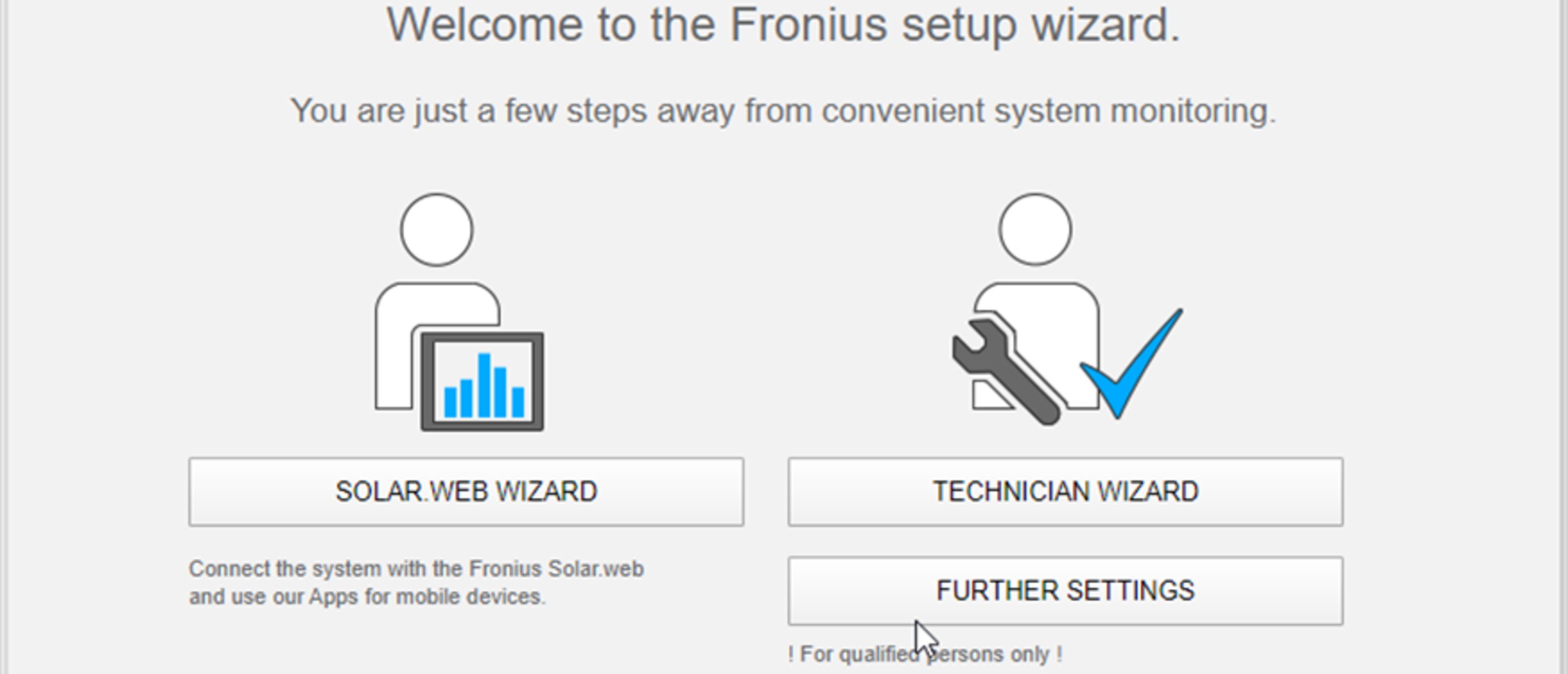
The technician wizard is intended for the installer and contains standard-specific settings. Running the technician wizard is optional.
If the technician wizard is run, it is vital to note the service password that is issued. This service password is necessary for setting the "DNO Editor" menu item.
If the technician wizard is not run, no specifications regarding power reduction are set.
Running the Fronius Solar.web wizards is mandatory.
The Fronius Solar.web homepage is displayed,
or
the Fronius Datamanager 2.0 web page is displayed.
Further information on the Fronius Datamanager 2.0 and other start-up options can be found at: | |
 | → http://www.fronius.com/QR-link/4204260191DE |

Item | Description |
|---|---|
(1) | Display |
| |
(2) | Initialisation LED (red) lights up
|
(3) | Status LED (orange) lights up
|
(4) | Operating status LED (green) lights up
|
| |
(5) | "Left/up" key |
(6) | "Down/right" key |
(7) | "Menu/Esc" key |
(8) | "Enter" key |
The keys operate capacitively. Exposure to water may impair their function. If necessary, wipe the keys dry with a cloth to ensure optimum functionality.
Power for the display comes from the mains voltage. Depending on the setting selected in the Setup menu, the display can be kept on all day. (For night mode, see section Display settings)
IMPORTANT! The display of the inverter is not a calibrated measuring device.
A slight deviation from the utility meter of the energy company is system-related. A calibrated meter will be needed to calculate the bills for the energy company.


| (*) | Scroll bar |
| (**) | Energy Manager icon is displayed when the "Energy Manager" function is activated For more information, see section Relay (floating contact switch) |
| (***) | Inv. no. = Inverter DATCOM number, Save symbol - appears briefly while set values are being saved, USB connection - appears if a USB flash drive has been connected |
If two minutes pass without any button being pressed, the display backlighting switches off automatically and the inverter goes to the "NOW" menu item (assuming the display backlighting is set to AUTO).
The automatic selection of the "NOW" menu item can happen from any position on the menu level, unless the inverter was manually switched into the "Standby" operating mode.
After automatically selecting the "NOW" menu item, the current power of feeding in is displayed.
 | 1Press "ESC"  |
 | The display switches to the menu level. 2Using the "Left" or "Right" keys  select the desired menu item select the desired menu item3Press the "Enter" key  to select the desired menu item to select the desired menu item |
Output power (W) - depending on the device type (MultiString), when the Enter key is pressed, |
AC reactive power (VAr) |
Grid voltage (V) |
Output current (A) |
Grid frequency (Hz) |
Solar voltage (V) - U PV1 from MPP Tracker 1 and U PV2 from MPP Tracker 2 (MPPT1 / MPPT2), if MPP Tracker 2 is activated (see "The Basic menu" - "Menu items in the Basic menu") |
Solar power (A) - I PV1 from MPP Tracker 1 and I PV2 from MPP Tracker 2 (MPPT1 / MPPT2), if MPP Tracker 2 is activated (see "The Basic menu" - "Menu items in the Basic menu") |
Time date - Time and date on the inverter or in the Fronius Solar Net ring |
Energy fed in (kWh / MWh) There may be discrepancies compared with values displayed on other measuring instruments because of differences in measuring methods. As far as the billing of the energy fed in is concerned, the only binding display values are those produced by the calibrated measuring instrument provided by the utility company. |
Max. output power (W) |
Yield Like the "Energy fed in" figure, the yield figure may also exhibit discrepancies compared with other measured values. The subitem "Energy yield" in the "Menu items in the Set-up menu" section explains how to select a currency and charge rate. |
CO2 savings The subitem "CO2 factor" in the "Menu items in the Set-up menu" section explains how to set the CO2 factor. |
Maximum grid voltage (V) [phase indicator - neutral or phase - phase] |
Maximum solar voltage (V) |
Operating hours IMPORTANT! In order for the day and year values to be displayed correctly, the time must be set accurately. |
The inverter is pre-configured after commissioning has been completely carried out (e.g. using the Installation Wizard) according to the country setup.
The SETUP menu item allows the initial settings of the inverter to be changed easily to bring it in line, as closely as possible, with the preferences and requirements of the user.
IMPORTANT! As a result of software updates, you may find that your device has certain functions that are not described in these Operating Instructions, or vice versa. Certain illustrations may also differ slightly from the actual controls on your device, but these controls function in exactly the same way.
Entering the SETUP menu item | |
 | 1At the menu level, use the "Left" or "Right" keys to select the "SETUP" menu item |
2Press the "Enter" key | |
| |
 | The first entry under the SETUP menu item is displayed: |
Scrolling between the entries | |
 | 3Use the "Up" and "Down" keys  to scroll between the available entries to scroll between the available entries |
Exiting an entry | |
| 4To exit a menu entry, press the "Back" key The menu level appears |
If no key is pressed for 2 minutes:
The available settings are displayed: |
| The first digit of a value to be set flashes: |
4Use the 'Up' or 'Down' buttons to select the desired setting 5Press the 'Enter' key to save and apply the setting. To discard the setting, press the 'Esc' key. | 4Use the 'Up' or 'Down' keys to select a value for the first digit 5Press "Enter" The second digit of the value flashes. 6Repeat steps 4 and 5 until ... the whole value to be set flashes. | |
| 7Press "Enter" 8Repeat steps 4 - 6 as required for units or other values that are to be set until the appropriate unit or the value flashes. 9Press the 'Enter' key to save and apply the changes. To discard the changes, press the 'Esc' key. | |
The currently selected menu item is displayed. |
| The currently selected menu item is displayed. |
 | 1Select "Clock" from the Setup menu . |
2Press the "Enter" key | |
|
 | An overview of the values that can be changed is displayed. |
3Use the "Up" and "Down" keys Select "Set time" | |
4Press the "Enter" key |
 | The current time appears. (HH:MM:SS, 24-hour clock), the "tens" digit for the hour will flash. |
5Use the "Up" and "Down" keys  to select a value for the first digit of the code to select a value for the first digit of the code | |
6Press the "Enter" key |
 | The "units" digit for the hour will flash. |
7Repeat steps 5 and 6 to set the "units" digit for the hour, for the minutes and for the seconds until... |
 | the set time starts flashing. |
8Press the "Enter" key | |
| The time is applied and the overview of values that can be changed is displayed. |
4Press the "Esc"  key key |
| The "Clock" item on the Setup menu appears. |
Manual activation / deactivation of Standby mode
key"STANDBY" and "ENTER" appear alternately on the display.
Standby mode is now active.
The Startup LED shows steady orange.
gridThe "Standby" menu item is displayed.
At the same time, the inverter enters the startup phase.
The operating state LED shows steady green when feeding energy into the grid has been resumed.
Checking data communications, entering the inverter number, protocol settings
Setting range | Status / inverter number / protocol type |
Status | |
Inverter number | |
Setting range | 00 - 99 (00 = inverter address 100) |
Factory setting | 01 |
IMPORTANT! If a number of inverters are linked together in a data communications system, assign a unique address to each one. | |
Protocol type | |
Setting range | Solar Net / Interface * |
Factory setting | Fronius Solar Net |
* The protocol type "Interface" only functions when there is no Datamanager card in the inverter. All Fronius Datamanager cards should be removed from the inverter. | |
Running firmware updates or saving detailed information from the inverter to the USB flash drive
Setting range | Safely remove hardware / Software update / Logging interval |
Safely remove hardware
To remove a USB flash drive from the USB A socket on the plug-in data communications card without losing any data.
Software update
To update the inverter firmware using a USB flash drive.
To successfully update the inverter software, the USB flash drive provided for the purpose must not have a hidden partition or any encryption (see chapter "Suitable USB flash drives").
The inverter starts copying the data.
"BOOT" and the progress of storing the individual tests expressed in % are displayed until all the data for all the electronic modules has been copied.
Once copying is complete, the inverter updates the electronic modules as required in sequence.
"BOOT", the affected modules and the update progress in % are displayed.
The final step is for the inverter to update the display.
The display remains dark for approx. 1 minute while the monitoring and status LEDs flash.
Once the firmware update is complete, the inverter enters its start-up phase before going on to start feeding energy into the grid. Unplug the USB flash drive using the "Safely remove hardware" function.
When the inverter firmware is updated, any custom settings that were configured in the Setup menu are retained.
| Logging interval | |
Unit | Minutes | |
Setting range | 30 min. / 20 min./ 15 min./ 10 min./ 5 min./ No log | |
Factory setting | 30 min. | |
|
| |
30 min. | The logging interval is 30 minutes; every 30 minutes new logging data will be saved to the USB flash drive. | |
20 min. |  | |
15 min. | ||
10 min. | ||
5 min. | The logging interval is 5 minutes; every 5 minutes new logging data will be saved to the USB flash drive. | |
No log | No data is saved | |
IMPORTANT! In order for the USB logging function to work correctly the time must be set correctly. Setting the time is discussed in the section "Menu items in the Setup menu" - "Clock".
Status codes (state codes), the status of the inverter (e.g. feeding energy into the grid) or Energy Manager functions can be displayed using the floating switch contact (relay).
Setting range | Relay mode / Relay test / Switch-on point* / Switch-off point* |
* these are only shown if the "E-Manager" function has been activated under "Relay mode".
Relay mode
| |
Setting range | ALL / Permanent / GAF / OFF / ON / E-Manager |
Factory setting | ALL |
Alarm function: | ||
ALL / Permanent: | Switching the floating switch contact for permanent and temporary service codes (e.g. brief interruption to energy being fed into the grid, a service code occurs a certain number of times a day - can be adjusted in the "BASIC" menu) | |
GAF | As soon as GAF mode is selected, the relay is switched on. The relay opens as soon as the power stage set registers an error and goes from normally feeding energy into the grid to being in an error state. This means that the relay can be used for fail-safe functions. Application example | |
Active output: | ||
ON: | The floating NO contact is on all the time the inverter is in operation (as long as the display is not dark or is displaying something). | |
OFF: | The floating NO contact is off. | |
Energy Manager: | ||
E-Manager: | Further details on the "Energy Manager" function may be found in the "Energy Manager" section. | |
Relay test | ||
Switch-on point (only if "Energy Manager" function is activated) | ||
Factory setting | 1000 W |
Setting range | Set switch-off point up to the maximum nominal output of the inverter (W or kW) |
Switch-off point (only if "Energy Manager" function is activated) | |
Factory setting | 500 |
Setting range | 0 to the set switch-on point of the inverter (W or kW) |
The "Energy Manager" (E-Manager) function can be used to activate the floating switch contact in such a way that it functions as an actuator.
Thus, a consumer that is connected to the floating switch contact can be controlled by specifying a switch-on or switch-off point that depends on the feed-in power (effective power).
To activate the Energy Manager function, select the "E-Manager" item and press the "Enter" key.
When the "Energy Manager" function is running, the "Energy Manager" symbol will appear in the top left corner of the display:
 When the floating NO contact is off (open contact)
 When the floating NC contact is on (closed contact)
To deactivate the Energy Manager function, select a different function (ALL / Permanent / OFF / ON) and press the "Enter" key.
Notes on setting up the switch-on and switch-off points
If the difference between the switch-on and switch-off points is too small, or if there are fluctuations in effective power, the result may be multiple switching cycles.
To avoid switching on and off frequently, the difference between the switch-on and switch-off points should be at least 100 - 200 W.
When choosing the switch-off point, the power consumption of the connected consumer should be taken into account.
When choosing the switch-on point, the weather conditions and anticipated insolation should be taken into account.
Application example
Switch-on point = 2000 W, switch-off point = 1800 W
If the inverter is outputting 2000 W or above, then the floating switch contact on the inverter is switched on.
If the inverter output falls to below 1800 W, the floating switch contact is switched off.
This allows useful applications, such as operating a heat pump or an air-conditioning system using as much self-generated power as possible, to be implemented quickly
Set the time, date, the display format and automatic changeover between summer and winter time
Setting range | Set time / Set date / Time display format / Date display format / Summer/winter time |
Set time | |
Set date | |
Time display format | |
Setting range | 12hrs / 24hrs |
Factory setting | Depends on country setup |
Date display format | |
Setting range | mm/dd/yyyy or dd.mm.yy |
Factory setting | Depends on country setup |
Summer/winter time | |
IMPORTANT! Only use the automatic summer/winter time changeover function if the Fronius Solar Net ring does not include any LAN- or WLAN-compatible system components (e.g. Fronius Datalogger Web, Fronius Datamanager or Fronius Hybridmanager). | |
Setting range | on / off |
Factory setting | on |
IMPORTANT! The time and date must be set accurately in order for the day and year values and for the day characteristic to be displayed correctly. | |
Setting range | Language / Night mode / Contrast / Illumination |
Language | |
Setting range | English, German, French, Spanish, Italian, Dutch, Czech, Slovakian, Hungarian, Polish, Turkish, Portuguese, Romanian |
Night mode | |
Setting range | AUTO / ON / OFF |
Factory setting | OFF |
AUTO: | Fronius DATCOM mode is always in effect as long as there is a Fronius Datamanager connected in an active and uninterrupted Fronius Solar Net. | |
ON: | Fronius DATCOM mode is always in effect. The inverter supplies 12 V of DC voltage continuously to power the Fronius Solar Net. The display is always active. IMPORTANT! If Fronius DATCOM night mode is set to ON or AUTO when there are Fronius Solar Net components connected, the inverter's current consumption during the night will increase to around 7 W. | |
OFF: | Fronius DATCOM will not run at night, the inverter therefore does not require any power during the night to supply the Fronius Solar Net with energy. | |
Contrast | ||
Setting range | 0 - 10 |
Factory setting | 5 |
Since the contrast is temperature-dependent, it may be necessary to adjust the setting under the "Contrast" menu item when the environmental conditions change. | |
Illumination | |
The "Illumination" menu item only relates to the inverter display backlighting. | |
Setting range | AUTO / ON / OFF |
Factory setting | AUTO |
AUTO: | The inverter display backlighting is activated by pressing any key. If no key is pressed for 2 minutes, the display backlighting will go off again. | |
ON: | The inverter display backlighting remains permanently on when the inverter is active. | |
OFF: | The inverter display backlighting is permanently switched off. |
Setting range | Currency / Feed-in tariff |
Counter deviation / calibration | |
Currency | |
Setting range | 3 characters, A-Z |
Feed-in tariff | |
Setting range | 2 digits, 3 decimal places |
Factory setting | (depends on country setup) |
CO2 factor | |
To check that the fan is working correctly
Setting range | Test fan #1 / Test fan #2 (depending on the device) |
IMPORTANT! Nothing will show on the inverter display if the fan is working. The only way to check how the fan is working is by listening and feeling.
PV Ins.- Insulation resistance of the PV system
Ext. Lim. - external Limitation
U PV 1 / U PV 2* (U PV 2 is not available on the Fronius Symo 15.0-3 208)
Current DC voltage at the DC input terminals, even if the inverter is feeding no power into the grid whatsoever (from the 1st or 2nd MPP Tracker)
* MPP Tracker 2 must be switched to ON via the Basic menu
GVDPR - Grid voltage-dependent power reduction
Fan #1 - Percentage of target output for fan
IMPORTANT! Due to the low level of insolation early in the morning and in the evening, the status codes STATE 306 (Power low) and STATE 307 (DC low) are displayed routinely at these times of day. These status codes do not indicate any kind of fault at this point in time.
The status of the most recent inverter fault can be displayed.
For displaying the settings that will be of relevance to a power supply company. The values shown will depend on the country setup or the device-specific settings of the inverter.
General: | Device type - the exact name of the inverter |
Country-specific setting: | Setup - specified country setup |
MPP Tracker: | Tracker 1 - indicates the set tracking behaviour (MPP AUTO / MPP USER / FIX) |
Grid monitoring: | GMTi - Grid Monitoring Time - start-up time of the inverter in sec (seconds) |
Grid voltage limits inner limit value: | UImax - upper inner grid voltage in V (volts) |
Grid voltage limits outer limit value | UMax - upper outer grid voltage in V (volts) |
Grid frequency limits: | FILmax - upper inner grid frequency in Hz (Hertz) |
Q-mode: | Indicates which reactive power setting is currently active on the inverter (e.g. OFF, Q / P, etc.) |
AC power limit including SoftStart indicator and/or AC grid frequency derating: | Max P AC - maximum output power, which can be changed using the "Manual Power Reduction" function |
AC voltage derating: | GVDPRe - Grid Voltage Depending Power Reduction enable limit - threshold value in V from which voltage-dependent power derating starts |
*cyl = grid periods (cycles); 1 cyl corresponds to 20 ms at 50 Hz or 16.66 ms at 60 Hz | |
Displays the version and serial numbers of the PC boards in the inverter (e.g. for service purposes)
Display area | Display / Display Software / Integrity Checksum / Memory Card / Memory Card #1 / Power Stage / Power Stage Software / EMI Filter / Power Stage #3 / Power Stage #4 |
The inverter has a key lock function.
When the key lock is active, the Setup menu is not accessible, i.e. the setup data cannot be changed accidentally (or maliciously).
The code 12321 has to be entered in order to activate / deactivate the key lock.
The inverter has a key lock function.
When the key lock is active, the Setup menu is not accessible, i.e. the setup data cannot be changed accidentally (or maliciously).
The code 12321 has to be entered in order to activate / deactivate the key lock.
1Press the "Menu" key | |
| The menu level appears. 2Press the unassigned "Menu / Esc" key 5 times  |
 | "Access Code" is displayed in the "CODE" menu; the first digit starts flashing. |
3Enter the code 12321: Use the "Plus" and "Minus" keys to select a value for the first digit of the code | |
4Press the "Enter" key |
 | The second digit flashes. |
5Repeat steps 3 and 4 for the second, third, fourth and fifth digits of the access code until... the selected code starts flashing. 6Press the "Enter" key |
 | "Setup Menu Lock" is displayed in the "LOCK" menu. |
7Use the "Plus" and "Minus" keys to turn the key lock on or off:ON = key lock is on (the Setup menu is not accessible) OFF = key lock is off (the Setup menu is accessible) | |
8Press the "Enter" key |
If a USB flash drive is connected to the USB A socket it can function as a datalogger for an inverter.
At any time, the logging data stored on the USB flash drive can beOlder versions (before Excel 2007) are limited to a maximum of 65,536 rows.
Further information on "Data on a USB flash drive", "Data volume and storage capacity" as well as "Buffer memory" can be found at: | |
Fronius Symo 3 - 10 kW: | |
 | ® http://www.fronius.com/QR-link/4204260172EN |
Fronius Symo 10 - 20 kW, Fronius Eco: | |
 | ® http://www.fronius.com/QR-link/4204260175EN |
If a USB flash drive is connected to the USB A socket it can function as a datalogger for an inverter.
At any time, the logging data stored on the USB flash drive can beOlder versions (before Excel 2007) are limited to a maximum of 65,536 rows.
Further information on "Data on a USB flash drive", "Data volume and storage capacity" as well as "Buffer memory" can be found at: | |
Fronius Symo 3 - 10 kW: | |
| ® http://www.fronius.com/QR-link/4204260172EN |
Fronius Symo 10 - 20 kW, Fronius Eco: | |
| ® http://www.fronius.com/QR-link/4204260175EN |
Due to the variety of USB flash drives available on the market, it cannot be guaranteed that every USB flash drive will be detected by the inverter.
Fronius recommends that only certified, industry-grade USB flash drives are used (look out for the USB-IF logo).
The inverter supports USB flash drives with the following file systems:
Fronius recommends that the USB flash drive employed should only be used for recording logging data or updating the inverter software. The USB flash drives should not contain any other data.
USB symbol on the inverter display, e.g. in display mode "NOW":

If the inverter detects a USB flash drive, the USB symbol will appear in the top right corner of the display.
When inserting a USB flash drive, check whether the USB symbol is displayed (it may also flash).
IMPORTANT! Please note for outdoor applications that conventional USB flash drives are often only guaranteed to work within a restricted temperature range.
For outdoor applications ensure that the USB flash drive also functions, for example, at low temperatures.

With the help of the USB flash drive, end customers can also update the inverter software via the SETUP menu: the update file is first saved to the USB flash drive, from where it is then transferred to the inverter.
Safety instruction concerning the removal of a USB flash drive: | ||
 |
| IMPORTANT! To avoid any loss of data, a USB flash drive may only be removed if the following conditions are met:
|
| 1Press the "Menu” buttonThe menu level appears. 2Press the unassigned "Menu / Esc" key 5 times |
| "Access Code" is displayed in the "CODE" menu; the first digit starts flashing. |
3Enter the code 22742: Use the "Plus" and "Minus" keys to select a value for the first digit of the code | |
4Press the "Enter" button |
 | The second digit flashes. |
5Repeat steps 3 and 4 for the second, third, fourth and fifth digits of the access code until... the selected code starts flashing. 6Press the "Enter" button |
The Basic menu appears.
to select the desired entry button | 1Press the "Menu” buttonThe menu level appears. 2Press the unassigned "Menu / Esc" key 5 times |
| "Access Code" is displayed in the "CODE" menu; the first digit starts flashing. |
3Enter the code 22742: Use the "Plus" and "Minus" keys to select a value for the first digit of the code | |
4Press the "Enter" button |
| The second digit flashes. |
5Repeat steps 3 and 4 for the second, third, fourth and fifth digits of the access code until... the selected code starts flashing. 6Press the "Enter" button |
The Basic menu appears.
to select the desired entry button The Basic menu is used to set the following parameters, which are important for installing and operating the inverter: |
MPP Tracker 1 / MPP Tracker 2
|
|
USB log book
|
Input signal
|
SMS / relay
|
Isolation setting
|
TOTAL Reset To reset the values to zero, press the "Enter" key. |
If the option: DC SPD (surge protection) has been fitted in the inverter, the following menu items will be set by default:
Signal input: Ext Sig.
Triggering method: Warning
Connection type: N/C

Switching the inverter on again
Switching the inverter on again
The inverter performs a system self-diagnosis that automatically detects many faults that may occur and shows them on the display. This means you are promptly made aware of malfunctions in the inverter or the photovoltaic system, or of any installation or operating faults.
If the system self-diagnosis has detected a specific fault, the associated status code will be shown on the display.
IMPORTANT! Status codes may sometimes appear briefly as a result of the inverter's control response. If the inverter then continues working with no sign of any problem, this means that there was no fault.
Class 1 status codes generally only arise momentarily and are caused by the public grid.
Example: The grid frequency is too high and the inverter may not feed any energy into the grid owing to a standard. There is nothing wrong with the device.
The initial response of the inverter is to disconnect itself from the grid. The grid is subsequently checked during the stipulated monitoring period. If no further problem has been detected by the end of this period, then the inverter will resume feeding energy into the grid.
The GPIS SoftStart function is activated according to the country setup:
After cutting out due to an AC error, the output power of the inverter is continuously increased in line with the national guidelines.
Code | Description | Behaviour | Remedy |
|---|---|---|---|
102 | AC voltage too high | Following careful testing and when the grid conditions are within the permissible range again, the inverter will resume feeding energy into the grid. | Check grid connections; |
103 | AC voltage too low | ||
105 | AC frequency too high | ||
106 | AC frequency too low | ||
107 | No AC grid | ||
108 | Stand-alone operation detected | ||
112 | RCMU error |
Class 3 includes status codes that may occur while feeding energy into the grid, but generally do not cause the process to be interrupted for any length of time.
The inverter disconnects automatically from the grid, the grid is then monitored as specified and the inverter attempts to resume feeding energy into the grid.
Code |
| Description |
| Behaviour |
| Remedy |
|---|---|---|---|---|---|---|
301 |
| Overcurrent (AC) |
| Short-term interruption while feeding energy into the grid. |
| *) |
302 |
| Overcurrent (DC) |
|
| ||
303 |
| DC module overtemperature |
| Short-term interruption while feeding energy into the grid. |
| Purge cooling air openings and heat sink; **) |
304 |
| AC module overtemperature |
|
| ||
305 |
| No power being fed in, despite closed relay |
| Short-term interruption while feeding energy into the grid. |
| **) |
306 |
| PV output too low for feeding energy into the grid |
| Short-term interruption while feeding energy into the grid |
| wait for sufficient level of insolation; |
307 |
| DC low |
|
| ||
IMPORTANT! Due to the low level of insolation early in the morning and in the evening, the status codes 306 (Power low) and 307 (DC low) are displayed routinely at these times of day. These status codes do not indicate any kind of fault. | ||||||
308 |
| Intermediate circuit voltage too high | Short-term interruption while feeding energy into the grid |
| **) | |
309 |
| DC input voltage MPPT 1 too high | ||||
311 |
| Polarity of DC strings reversed | ||||
313 |
| DC input voltage MPPT2 too high | ||||
314 |
| Current sensor calibration timeout |
| Short-term interruption while feeding energy into the grid. |
| *) |
315 |
| AC current sensor error | ||||
316 |
| InterruptCheck fail | ||||
325 |
| Overtemperature in the connection area | ||||
326 |
| Fan 1 error | ||||
327 |
| Fan 2 error | ||||
*) If the status code is displayed all the time: notify a Fronius-trained service engineer
**) Fault is rectified automatically. If this status code keeps recurring, contact your system engineer
Some of the class 4 status codes necessitate intervention by a Fronius-trained service technician.
Code |
| Description |
| Behaviour |
| Remedy |
|---|---|---|---|---|---|---|
401 |
| Unable to communicate with the power stage set |
| The inverter will automatically attempt to connect again and, if possible, will resume feeding energy into the grid |
| *) |
406 |
| AC module temperature sensor faulty (L1) |
|
| ||
407 |
| AC module temperature sensor faulty (L2) |
|
| ||
408 |
| DC component measured in the grid too high |
|
| ||
412 |
| Fixed voltage mode has been selected instead of MPP voltage mode, and the fixed voltage has been set to too low or too high a value. |
| - |
| **) |
415 |
| Safety cut-out via option card or RECERBO has triggered |
| The inverter is not feeding any energy into the grid. |
| *) |
416 |
| No communication possible between power stage set and control system. |
| The inverter will automatically attempt to connect again and, if possible, will resume feeding energy into the grid |
| *) |
417 |
| Hardware ID problem |
| The inverter will automatically attempt to connect again and, if possible, will resume feeding energy into the grid |
| Update inverter firmware; *) |
419 |
| Unique ID conflict | ||||
420 |
| No communication possible with the Fronius Datamanager | ||||
421 |
| HID range error | ||||
425 |
| Unable to communicate with the power stage set | ||||
426 - 428 |
| Possible hardware fault | ||||
431 |
| Software problem |
| The inverter is not feeding any energy into the grid. |
| Perform AC reset (switch automatic circuit breaker off and on again); update inverter firmware; *) |
436 |
| Functional incompatibility (one or more PC boards in the inverter are not compatible with each other, e.g. after a PC board has been replaced) |
| The inverter will automatically attempt to connect again and, if possible, will resume feeding energy into the grid |
| Update inverter firmware; *) |
437 |
| Power stage set problem | ||||
438 |
| Functional incompatibility (one or more PC boards in the inverter are not compatible with each other, e.g. after a PC board has been replaced) |
| The inverter will automatically attempt to connect again and, if possible, will resume feeding energy into the grid |
| Update inverter firmware; *) |
443 |
| Intermediate circuit voltage too low or asymmetric |
| The inverter is not feeding any energy into the grid. |
| *) |
445 |
|
|
| The inverter is not feeding any energy into the grid. |
| Update inverter firmware; *) |
447 |
| Insulation fault |
| The inverter is not feeding any energy into the grid. |
| *) |
448 |
| Neutral conductor not connected | ||||
450 |
| Guard cannot be found | ||||
451 |
| Memory error detected |
| The inverter will automatically attempt to connect again and, if possible, will resume feeding energy into the grid |
| *) |
452 |
| Communication error between the processors | ||||
453 |
| Grid voltage and power stage set are incompatible | ||||
454 |
| Grid frequency and power stage set are incompatible | ||||
456 |
| Anti-islanding function is no longer being implemented correctly | ||||
457 |
| Grid voltage relay fault | The inverter is not feeding any energy into the grid. | Check AC cable *) | ||
458 | Error when recording measuring signal |
| The inverter is not feeding any energy into the grid. |
| *) | |
459 |
| Error when recording the measuring signal for the insulation test | ||||
460 |
| Reference voltage source for the digital signal processor (DSP) is working out of tolerance | ||||
461 | DSP data memory error | |||||
462 |
| Error during DC feed monitoring routine | ||||
463 |
| Reversed AC polarity, AC connector inserted incorrectly | ||||
474 |
| RCMU sensor faulty | The inverter is not feeding any energy into the grid. | **) | ||
475 |
| Insulation fault (connection between solar module and ground) | ||||
476 |
| Driver supply voltage too low | ||||
479 |
| Intermediate circuit voltage relay is switched off | The inverter will automatically attempt to connect again and, if possible, will resume feeding energy into the grid | *) | ||
480, |
| Functional incompatibility (one or more PC boards in the inverter are not compatible with each other, e.g. after a PC board has been replaced) |
| The inverter is not feeding any energy into the grid. |
| Update inverter firmware; *) |
482 |
| Setup interrupted after initial start-up |
| The inverter is not feeding any energy into the grid. |
| Restart Setup after an AC reset (switch automatic circuit breaker off and on again) |
483 |
| Voltage UDC fixed on MPP2 string out of limits |
| The inverter is not feeding any energy into the grid. |
| Check MPP settings; *) |
485 |
| CAN transmit buffer is full |
| The inverter is not feeding any energy into the grid. |
| Perform AC reset (switch automatic circuit breaker off and on again; *) |
489 |
| Permanent overvoltage on intermediate circuit capacitor (five 479 status codes in a row) |
| The inverter is not feeding any energy into the grid. |
| *) |
*) If the status code is displayed all the time: notify a Fronius-trained service technician
**) If this status code keeps recurring, contact your system engineer
Class 5 status codes do not generally interfere with feeding energy into the grid, but can cause restrictions. These status codes are displayed until they are acknowledged by pressing a key (however, the inverter continues to operate normally in the background).
Code |
| Description |
| Behaviour |
| Remedy |
|---|---|---|---|---|---|---|
502 |
| Insulation error on the solar modules |
| Warning message is shown on the display |
| **) |
509 |
| No energy fed into the grid in the past 24 hours |
| Warning message is shown on the display |
| Acknowledge status code; |
515 |
| Unable to communicate with filter |
| Warning message on the display |
| *) |
516 |
| No communication possible with the storage unit |
| Storage unit warning message |
| *) |
517 |
| Power derating caused by too high a temperature |
| When power derating occurs, a warning message is shown on the display. |
| If necessary, purge cooling air openings and heat sink; |
518 |
| Internal DSP malfunction |
| Warning message on the display |
| *) |
519 |
| No communication possible with the storage unit |
| Storage unit warning message |
| *) |
520 |
| No energy fed into the grid by MPPT1 in the past 24 hours |
| Warning message is shown on the display |
| Acknowledge status code; |
522 |
| DC low String 1 |
| Warning message on the display |
| *) |
523 |
| DC low String 2 |
| |||
558, |
| Functional incompatibility (one or more PC boards in the inverter are not compatible with each other, e.g. after a PC board has been replaced) |
| Warning message on the display | Update inverter firmware; *) | |
560 |
| Power derating caused by overfrequency |
| Displayed when grid frequency becomes excessively high. The power is reduced. |
| As soon as the grid frequency is back within the permissible range and the inverter has returned to normal operation, the fault is rectified automatically; **) |
564 |
| Functional incompatibility (one or more PC boards in the inverter are not compatible with each other, e.g. after a PC board has been replaced) |
| Warning message on the display |
| Update inverter firmware; *) |
566 |
| Arc detector switched off |
| The status code is displayed every day until the arc detector is reactivated. |
| No error |
568 |
| Incorrect input signal on the multifunction current interface |
| The status code is displayed in the case of an incorrect input signal on the multifunction current interface and with the following setting: |
| Acknowledge status code; |
572 |
| Power limited by the power stage set |
| Power is being limited by the power stage set |
| *) |
573 |
| Undertemperature warning |
| Warning message on the display |
| *) |
581 |
| "Special Purpose Utility-Interactive" (SPUI) setup activated |
| The inverter is no longer compliant with the IEEE1547 and IEEE1574.1 standards because the standalone function has been deactivated, a frequency-dependent power reduction has been activated and the frequency and voltage limits are being changed |
| No error |
*) If the status code is displayed all the time: Notify a Fronius-trained service technician.
**) If this status code keeps recurring, contact your system engineer.
Some of the class 6 status codes necessitate intervention by a Fronius-trained service engineer.
Code |
| Description |
| Behaviour |
| Remedy |
|---|---|---|---|---|---|---|
601 |
| CAN bus is full |
| The inverter is not feeding any energy into the grid. |
| Update inverter firmware; *) |
603 |
| AC module temperature sensor faulty (L3) |
| The inverter will automatically attempt to connect again and, if possible, will resume feeding energy into the grid |
| *) |
604 |
| DC module temperature sensor faulty |
|
| ||
607 |
| RCMU error |
| The inverter is not feeding any energy into the grid. |
| Reset status code by pressing 'Enter'. The inverter resumes the feeding of energy into the grid; if the status code keeps appearing, check the complete photovoltaic system for damage; **) |
608 |
| Functional incompatibility (one or more PC boards in the inverter are not compatible with each other, e.g. after a PC board has been replaced) |
| The inverter is not feeding any energy into the grid. |
| Update inverter firmware; *) |
*) If the status code is displayed all the time: notify a Fronius-trained service engineer
**) Fault is rectified automatically. If this status code keeps recurring, contact your system engineer
Class 7 status codes relate to the control system, the configuration and inverter data recording, and may directly or indirectly affect the process of feeding energy into the grid.
Code |
| Description |
| Behaviour |
| Remedy |
|---|---|---|---|---|---|---|
701 - 704 |
| Provides information about the internal processor status |
| Warning message on the display |
| *) |
705 |
| Conflict when setting the inverter number (e.g. number already assigned) |
| - |
| Correct inverter number in Setup menu |
706 - 716 |
| Provides information about the internal processor status |
| Warning message on the display |
| *) |
721 |
| EEPROM has been re-initialised |
| Warning message on the display |
| Acknowledge status code; *) |
722 - 730 |
| Provides information about the internal processor status |
| Warning message on the display |
| *) |
731 |
| Initialisation error - USB flash drive is not supported |
| Warning message on the display |
| Check or replace USB flash drive |
732 |
| Initialisation error - Overcurrent on USB flash drive |
| |||
733 |
| No USB flash drive connected |
| Warning message on the display |
| Connect or check USB flash drive; *) |
734 |
| Update file not recognised or not present |
| Warning message on the display |
| Check update file (e.g. for correct file name) |
735 |
| Update file does not match the device, update file too old |
| Warning message on the display, update process is interrupted |
| Check update file |
736 |
| Write or read error occurred |
| Warning message on the display |
| Check USB flash drive and the data contained on it or replace USB flash drive |
737 |
| File could not be opened |
| Warning message on the display |
| Remove and then reinsert USB flash drive; check or replace USB flash drive |
738 |
| Log file cannot be saved (e.g. USB flash drive is write-protected or full) |
| Warning message on the display |
| Create some storage space, remove write protection, if necessary check or replace USB flash drive; *) |
740 |
| Initialisation error - error in file system on USB flash drive |
| Warning message on the display |
| Check USB flash drive; reformat on PC for FAT12, FAT16 or FAT32 |
741 |
| Error during recording of logging data |
| Warning message on the display |
| Remove and then reinsert USB flash drive; check or replace USB flash drive |
743 |
| Error occurred during update process |
| Warning message on the display |
| Repeat update process, check USB flash drive; *) |
745 |
| Update file corrupt |
| Warning message on the display, update process is interrupted |
| Download update file again; check or replace USB flash drive; *) |
746 |
| Error occurred during update process |
| Warning message on the display, update process is interrupted |
| Wait for two minutes, then start the update again; *) |
751 |
| Time lost |
| Warning message on the display |
| Reset time and date on the inverter; *) |
752 |
| Real Time Clock module communication error |
| |||
753 |
| Internal error: Real Time Clock module is in emergency mode |
| Time may be inaccurate or lost (feeding energy into the grid normal) |
| Reset time and date on the inverter |
754 - 755 |
| Provides information about the internal processor status |
| Warning message on the display |
| *) |
757 |
| Hardware error in the Real Time Clock module |
| Error message on the display; the inverter is not feeding any energy into the grid |
| *) |
758 |
| Internal error: Real Time Clock module is in emergency mode |
| Time may be inaccurate or lost (feeding energy into the grid normal) |
| Reset time and date on the inverter |
760 |
| Internal hardware error |
| Error message on the display |
| *) |
761 - 765 |
| Provides information about the internal processor status |
| Warning message on the display |
| *) |
766 |
| Emergency power limitation has been activated (max. 750 W) |
| Error message on the display | ||
767 |
| Provides information about the internal processor status |
| Warning message on the display |
| *) |
768 |
| Different power limitation in the hardware modules | ||||
772 |
| Storage unit not available | ||||
773 |
| Software update group 0 (invalid country setup) | ||||
775 |
| PMC power stage set not available |
| Warning message on the display |
| Press 'Enter' key to acknowledge error; *) |
776 |
| Invalid device type | ||||
781 - 794 |
| Provides information about the internal processor status |
| Warning message on the display |
| *) |
*) If the status code is displayed all the time: Notify a Fronius-trained service technician
1000 - 1299- Provide information on the status of the internal processor program | |
Description | Is of no concern when the inverter is working properly and only appears in the "Status PS" setup parameter. In the event of an actual error, this status code assists Fronius Technical Support during the error analysis. |
When operating the inverter in extremely dusty environments:
when necessary, clean the cooling elements and fan on the back of the inverter as well as the air intakes at the mounting bracket using clean compressed air.
Fronius Symo | 3.0-3-S |
|---|---|
Input data |
|
MPP voltage range | 200–800 V DC |
Max. input voltage | 1000 V DC |
Min. input voltage | 150 V DC |
Max. input current | 16.0 A |
Max. short-circuit current module array 8) | 24.0 A |
Max. inverter backfeed current to the array 3) | 32 A (RMS)4) |
Output data | |
Nominal output power (Pnom) | 3000 W |
Max. output power | 3000 W |
Rated apparent power | 3000 VA |
Nominal mains voltage | 3~ NPE 400 / 230 V or 3~ NPE 380 / 220 V |
Min. grid voltage | 150 V / 260 V |
Max. grid voltage | 280 V / 485 V |
Nominal output current at 220 / 230 V | 4.5 / 4.3 A |
Max. output current | 9 A |
Nominal frequency | 50 / 60 Hz 1) |
Initial short circuit alternating current / phase IK | 9 A |
Total harmonic distortion | < 3 % |
Power factor (cos phi) | 0.7–1 ind./cap.2) |
Current (inrush) 5) | 38 A / 2 ms |
Maximum output fault current / duration | 21.4 A / 1 ms |
General data | |
Maximum efficiency | 98% |
European efficiency | 96.2% |
Self-consumption at night | < 0.7 W & < 3 VA |
Cooling | Controlled forced-air ventilation |
Protection class | IP 65 |
Dimensions h x w x d | 645 x 431 x 204 mm |
Weight | 16 kg |
Permitted ambient temperature | -25 °C - +60 °C |
Permissible humidity | 0–100% |
EMC device class | B |
DC / AC overvoltage category | 2/3 |
Pollution degree | 2 |
Noise emission | 58.3 dB(A) ref. 1pW |
Inverter topology | Non-insulated transformerless |
Protection devices | |
DC isolation measurement | Integrated |
DC overload performance | Operating point shift, power limiter |
DC disconnector | Integrated |
RCMU | Integrated |
Active anti-islanding method | Frequency conversion method |
Fronius Symo | 3.7-3-S |
|---|---|
Input data |
|
MPP voltage range | 250–800 V DC |
Max. input voltage | 1000 V DC |
Min. input voltage | 150 V DC |
Max. input current | 16.0 A |
Max. short-circuit current module array 8) | 24.0 A |
Max. inverter backfeed current to the array 3) | 32 A (RMS)4) |
Output data | |
Nominal output power (Pnom) | 3700 W |
Max. output power | 3700 W |
Rated apparent power | 3700 VA |
Nominal mains voltage | 3~ NPE 400 / 230 V or 3~ NPE 380 / 220 V |
Min. grid voltage | 150 V / 260 V |
Max. grid voltage | 280 V / 485 V |
Nominal output current at 220 / 230 V | 5.6 / 5.4 A |
Max. output current | 9 A |
Nominal frequency | 50 / 60 Hz 1) |
Initial short circuit alternating current / phase IK | 9 A |
Total harmonic distortion | < 3 % |
Power factor (cos phi) | 0.7–1 ind./cap.2) |
Current (inrush) 5) | 38 A / 2 ms |
Maximum output fault current / duration | 21.4 A / 1 ms |
General data | |
Maximum efficiency | 98% |
European efficiency | 96.7% |
Self-consumption at night | < 0.7 W & < 3 VA |
Cooling | Controlled forced-air ventilation |
Protection class | IP 65 |
Dimensions h x w x d | 645 x 431 x 204 mm |
Weight | 16 kg |
Permitted ambient temperature | -25 °C - +60 °C |
Permissible humidity | 0–100% |
EMC device class | B |
DC / AC overvoltage category | 2/3 |
Pollution degree | 2 |
Noise emission | 58.3 dB(A) ref. 1pW |
Inverter topology | Non-insulated transformerless |
Protection devices | |
DC isolation measurement | Integrated |
DC overload performance | Operating point shift, power limiter |
DC disconnector | Integrated |
RCMU | Integrated |
Active anti-islanding method | Frequency conversion method |
Fronius Symo | 4.5-3-S |
|---|---|
Input data |
|
MPP voltage range | 300–800 V DC |
Max. input voltage | 1000 V DC |
Min. input voltage | 150 V DC |
Max. input current | 16.0 A |
Max. short-circuit current module array 8) | 24.0 A |
Max. inverter backfeed current to the array 3) | 32 A (RMS)4) |
Output data | |
Nominal output power (Pnom) | 4500 W |
Max. output power | 4500 W |
Rated apparent power | 4500 VA |
Nominal mains voltage | 3~ NPE 400 / 230 V or 3~ NPE 380 / 220 V |
Min. grid voltage | 150 V / 260 V |
Max. grid voltage | 280 V / 485 V |
Nominal output current at 220 / 230 V | 6.8 / 6.5 A |
Max. output current | 9 A |
Nominal frequency | 50 / 60 Hz 1) |
Initial short circuit alternating current / phase I K | 9 A |
Total harmonic distortion | < 3 % |
Power factor (cos phi) | 0.7–1 ind./cap.2) |
Current (inrush) 5) | 38 A / 2 ms |
Maximum output fault current / duration | 21.4 A / 1 ms |
General data | |
Maximum efficiency | 98% |
European efficiency | 97% |
Self-consumption at night | < 0.7 W & < 3 VA |
Cooling | Controlled forced-air ventilation |
Protection class | IP 65 |
Dimensions h x w x d | 645 x 431 x 204 mm |
Weight | 16 kg |
Permitted ambient temperature | -25 °C - +60 °C |
Permissible humidity | 0–100% |
EMC device class | B |
DC / AC overvoltage category | 2/3 |
Pollution degree | 2 |
Noise emission | 58.3 dB(A) ref. 1pW |
Inverter topology | Non-insulated transformerless |
Protection devices | |
DC isolation measurement | Integrated |
DC overload performance | Operating point shift, power limiter |
DC disconnector | Integrated |
RCMU | Integrated |
Active anti-islanding method | Frequency conversion method |
Fronius Symo | 3.0-3-M |
|---|---|
Input data | |
MPP voltage range | 150–800 V DC |
Max. input voltage | 1000 V DC |
Min. input voltage | 150 V DC |
Max. input current | 2 x 16.0 A |
Max. short-circuit current module array (MPPT1 / MPPT2) 8) | 31 A / 31 A |
Max. inverter backfeed current to the array 3) | 48 A (RMS)4) |
Output data | |
Nominal output power (Pnom) | 3000 W |
Max. output power | 3000 W |
Rated apparent power | 3000 VA |
Nominal mains voltage | 3~ NPE 400 / 230 V or 3~ NPE 380 / 220 |
Min. grid voltage | 150 V / 260 V |
Max. grid voltage | 280 V / 485 V |
Nominal output current at 220 / 230 V | 4.6 / 4.4 A |
Max. output current | 13.5 A |
Nominal frequency | 50 / 60 Hz 1) |
Initial short circuit alternating current / phase IK | 13.5 A |
Total harmonic distortion | < 3 % |
Power factor (cos phi) | 0.85–1 ind./cap.2) |
Current (inrush) 5) | 38 A / 2 ms |
Maximum output fault current / duration | 24 A / 6.6 ms |
General data | |
Maximum efficiency | 98% |
European efficiency | 96.5% |
Self-consumption at night | < 0.7 W & < 3 VA |
Cooling | Controlled forced-air ventilation |
Protection class | IP 65 |
Dimensions h x w x d | 645 x 431 x 204 mm |
Weight | 19.9 kg |
Permitted ambient temperature | -25 °C - +60 °C |
Permissible humidity | 0–100% |
EMC device class | B |
DC / AC overvoltage category | 2/3 |
Pollution degree | 2 |
Noise emission | 59.5 dB(A) ref. 1pW |
Inverter topology | Non-insulated transformerless |
Protection devices | |
DC isolation measurement | Integrated |
DC overload performance | Operating point shift, power limiter |
DC disconnector | Integrated |
RCMU | Integrated |
Active anti-islanding method | Frequency conversion method |
Fronius Symo | 3.7-3-M |
|---|---|
Input data | |
MPP voltage range | 150–800 V DC |
Max. input voltage | 1000 V DC |
Min. input voltage | 150 V DC |
Max. input current | 2 x 16.0 A |
Max. short-circuit current module array (MPPT1 / MPPT2) 8) | 31 A / 31 A |
Max. inverter backfeed current to the array 3) | 48 A (RMS)4) |
Output data | |
Nominal output power (Pnom) | 3700 W |
Max. output power | 3700 W |
Rated apparent power | 3700 VA |
Nominal mains voltage | 3~ NPE 400 / 230 V or 3~ NPE 380 / 220 |
Min. grid voltage | 150 V / 260 V |
Max. grid voltage | 280 V / 485 V |
Nominal output current at 220 / 230 V | 5.6 / 5.4 A |
Max. output current | 13.5 A |
Nominal frequency | 50 / 60 Hz 1) |
Initial short circuit alternating current / phase IK | 13.5 A |
Total harmonic distortion | < 3 % |
Power factor (cos phi) | 0.85–1 ind./cap.2) |
Current (inrush) 5) | 38 A / 2 ms |
Maximum output fault current / duration | 24 A / 6.6 ms |
General data | |
Maximum efficiency | 98% |
European efficiency | 96.9% |
Self-consumption at night | < 0.7 W & < 3 VA |
Cooling | Controlled forced-air ventilation |
Protection class | IP 65 |
Dimensions h x w x d | 645 x 431 x 204 mm |
Weight | 19.9 kg |
Permitted ambient temperature | -25 °C - +60 °C |
Permissible humidity | 0–100% |
EMC device class | B |
DC / AC overvoltage category | 2/3 |
Pollution degree | 2 |
Noise emission | 59.5 dB(A) ref. 1pW |
Inverter topology | Non-insulated transformerless |
Protection devices | |
DC isolation measurement | Integrated |
DC overload performance | Operating point shift, power limiter |
DC disconnector | Integrated |
RCMU | Integrated |
Active anti-islanding method | Frequency conversion method |
Fronius Symo | 4.5-3-M |
|---|---|
Input data | |
MPP voltage range | 150–800 V DC |
Max. input voltage | 1000 V DC |
Min. input voltage | 150 V DC |
Max. input current | 2 x 16.0 A |
Max. short-circuit current module array (MPPT1 / MPPT2) 8) | 31 A / 31 A |
Max. inverter backfeed current to the array 3) | 48 A (RMS)4) |
Output data | |
Nominal output power (Pnom) | 4500 W |
Max. output power | 4500 W |
Rated apparent power | 4500 VA |
Nominal mains voltage | 3~ NPE 400 / 230 V or 3~ NPE 380 / 220 |
Min. grid voltage | 150 V / 260 V |
Max. grid voltage | 280 V / 485 V |
Nominal output current at 220 / 230 V | 6.8 / 6.5 A |
Max. output current | 13.5 A |
Nominal frequency | 50 / 60 Hz 1) |
Initial short circuit alternating current / phase IK | 13.5 A |
Total harmonic distortion | < 3 % |
Power factor (cos phi) | 0.85–1 ind./cap.2) |
Current (inrush) 5) | 38 A / 2 ms |
Maximum output fault current / duration | 24 A / 6.6 ms |
General data | |
Maximum efficiency | 98% |
European efficiency | 97.2% |
Self-consumption at night | < 0.7 W & < 3 VA |
Cooling | Controlled forced-air ventilation |
Protection class | IP 65 |
Dimensions h x w x d | 645 x 431 x 204 mm |
Weight | 19.9 kg |
Permitted ambient temperature | -25 °C - +60 °C |
Permissible humidity | 0–100% |
EMC device class | B |
DC / AC overvoltage category | 2/3 |
Pollution degree | 2 |
Noise emission | 59.5 dB(A) ref. 1pW |
Inverter topology | Non-insulated transformerless |
Protection devices | |
DC isolation measurement | Integrated |
DC overload performance | Operating point shift, power limiter |
DC disconnector | Integrated |
RCMU | Integrated |
Active anti-islanding method | Frequency conversion method |
Fronius Symo | 5.0-3-M |
|---|---|
Input data | |
MPP voltage range | 163–800 V DC |
Max. input voltage | 1000 V DC |
Min. input voltage | 150 V DC |
Max. input current | 2 x 16.0 A |
Max. short-circuit current module array (MPPT1 / MPPT2) 8) | 31 A / 31 A |
Max. inverter backfeed current to the array 3) | 48 A (RMS)4) |
Output data | |
Nominal output power (Pnom) | 5000 W |
Max. output power | 5000 W |
Rated apparent power | 5000 VA |
Nominal mains voltage | 3~ NPE 400 / 230 V or 3~ NPE 380 / 220 |
Min. grid voltage | 150 V / 260 V |
Max. grid voltage | 280 V / 485 V |
Nominal output current at 220 / 230 V | 7.6 / 7.3 A |
Max. output current | 13.5 A |
Nominal frequency | 50 / 60 Hz 1) |
Initial short circuit alternating current / phase IK | 13.5 A |
Total harmonic distortion | < 3 % |
Power factor (cos phi) | 0.85–1 ind./cap.2) |
Current (inrush) 5) | 38 A / 2 ms |
Maximum output fault current / duration | 24 A / 6.6 ms |
General data | |
Maximum efficiency | 98% |
European efficiency | 97.3% |
Self-consumption at night | < 0.7 W & < 3 VA |
Cooling | Controlled forced-air ventilation |
Protection class | IP 65 |
Dimensions h x w x d | 645 x 431 x 204 mm |
Weight | 19.9 kg |
Permitted ambient temperature | -25 °C - +60 °C |
Permissible humidity | 0–100% |
EMC device class | B |
DC / AC overvoltage category | 2/3 |
Pollution degree | 2 |
Noise emission | 59.5 dB(A) ref. 1pW |
Inverter topology | Non-insulated transformerless |
Protection devices | |
DC isolation measurement | Integrated |
DC overload performance | Operating point shift, power limiter |
DC disconnector | Integrated |
RCMU | Integrated |
Active anti-islanding method | Frequency conversion method |
Fronius Symo | 6.0-3-M |
|---|---|
Input data | |
MPP voltage range | 195–800 V DC |
Max. input voltage | 1000 V DC |
Min. input voltage | 150 V DC |
Max. input current | 2 x 16.0 A |
Max. short-circuit current module array (MPPT1 / MPPT2) 8) | 31 A / 31 A |
Max. inverter backfeed current to the array 3) | 48 A (RMS)4) |
Output data | |
Nominal output power (Pnom) | 6000 W |
Max. output power | 6000 W |
Rated apparent power | 6000 VA |
Nominal mains voltage | 3~ NPE 400 / 230 V or 3~ NPE 380 / 220 |
Min. grid voltage | 150 V / 260 V |
Max. grid voltage | 280 V / 485 V |
Nominal output current at 220 / 230 V | 9.1 / 8.7 A |
Max. output current | 13.5 A |
Nominal frequency | 50 / 60 Hz 1) |
Initial short circuit alternating current / phase IK | 13.5 A |
Total harmonic distortion | < 3 % |
Power factor (cos phi) | 0.85–1 ind./cap.2) |
Current (inrush) 5) | 38 A / 2 ms |
Maximum output fault current / duration | 24 A / 6.6 ms |
General data | |
Maximum efficiency | 98% |
European efficiency | 97.5% |
Self-consumption at night | < 0.7 W & < 3 VA |
Cooling | Controlled forced-air ventilation |
Protection class | IP 65 |
Dimensions h x w x d | 645 x 431 x 204 mm |
Weight | 19.9 kg |
Permitted ambient temperature | -25 °C - +60 °C |
Permissible humidity | 0–100% |
EMC device class | B |
DC / AC overvoltage category | 2/3 |
Pollution degree | 2 |
Noise emission | 59.5 dB(A) ref. 1pW |
Inverter topology | Non-insulated transformerless |
Protection devices | |
DC isolation measurement | Integrated |
DC overload performance | Operating point shift, power limiter |
DC disconnector | Integrated |
RCMU | Integrated |
Active anti-islanding method | Frequency conversion method |
Fronius Symo | 7.0-3-M |
|---|---|
Input data | |
MPP voltage range | 228–800 V DC |
Max. input voltage | 1000 V DC |
Min. input voltage | 150 V DC |
Max. input current | 2 x 16.0 A |
Max. short-circuit current module array (MPPT1 / MPPT2) 8) | 31 A / 31 A |
Max. inverter backfeed current to the array 3) | 48 A (RMS)4) |
Output data | |
Nominal output power (Pnom) | 7000 W |
Max. output power | 7000 W |
Rated apparent power | 7000 VA |
Nominal mains voltage | 3~ NPE 400 / 230 V or 3~ NPE 380 / 220 |
Min. grid voltage | 150 V / 260 V |
Max. grid voltage | 280 V / 485 V |
Nominal output current at 220 / 230 V | 10.6 / 10.2 A |
Max. output current | 13.5 A |
Nominal frequency | 50 / 60 Hz 1) |
Initial short circuit alternating current / phase I K | 13.5 A |
Total harmonic distortion | < 3 % |
Power factor (cos phi) | 0.85–1 ind./cap.2) |
Current (inrush) 5) | 38 A / 2 ms |
Maximum output fault current / duration | 24 A / 6.6 ms |
General data | |
Maximum efficiency | 98% |
European efficiency | 97.6% |
Self-consumption at night | < 0.7 W & < 3 VA |
Cooling | Controlled forced-air ventilation |
Protection class | IP 65 |
Dimensions h x w x d | 645 x 431 x 204 mm |
Weight | 21.9 kg |
Permitted ambient temperature | -25 °C - +60 °C |
Permissible humidity | 0–100% |
EMC device class | B |
DC / AC overvoltage category | 2/3 |
Pollution degree | 2 |
Noise emission | 59.5 dB(A) ref. 1pW |
Inverter topology | Non-insulated transformerless |
Protection devices | |
DC isolation measurement | Integrated |
DC overload performance | Operating point shift, power limiter |
DC disconnector | Integrated |
RCMU | Integrated |
Active anti-islanding method | Frequency conversion method |
Fronius Symo | 8.2-3-M |
|---|---|
Input data | |
MPP voltage range (PV1 / PV2) | 267–800 V DC |
Max. input voltage | 1000 V DC |
Min. input voltage | 150 V DC |
Max. input current (I PV1 / I PV2) | 2 x 16.0 A |
Max. short-circuit current module array (MPPT1 / MPPT2) 8) | 31 A / 31 A |
Max. inverter backfeed current to the array 3) | 48 A (RMS)4) |
Output data | |
Nominal output power (Pnom) | 8200 W |
Max. output power | 8200 W |
Rated apparent power | 8200 VA |
Nominal mains voltage | 3~ NPE 400 / 230 V or 3~ NPE 380 / 220 |
Min. grid voltage | 150 V / 260 V |
Max. grid voltage | 280 V / 485 V |
Nominal output current at 220 / 230 V | 12.4 / 11.9 A |
Max. output current | 13.5 A |
Nominal frequency | 50 / 60 Hz 1) |
Initial short circuit alternating current / phase IK | 13.5 A |
Total harmonic distortion | < 3 % |
Power factor (cos phi) | 0.85–1 ind./cap.2) |
Current (inrush) 5) | 38 A / 2 ms |
Maximum output fault current / duration | 24 A / 6.6 ms |
General data | |
Maximum efficiency | 98% |
European efficiency | 97.7% |
Self-consumption at night | < 0.7 W & < 3 VA |
Weight | 21.9 kg |
Noise emission | 59.5 dB(A) ref. 1pW |
Fronius Symo | 10.0-3-M |
|---|---|
Input data |
|
MPP voltage range | 270–800 V DC |
Max. input voltage | 1000 V DC |
Min. input voltage | 200 V DC |
Max. input current (MPP1 / MPP2) | 27.0 / 16.5 A (14 A for voltages < 420 V) |
Max. short-circuit current module array (MPPT1 / MPPT2) 8) | 56 A / 34 A |
Max. inverter backfeed current to the array 3) | 40.5 / 24.8 A (RMS)4) |
Output data | |
Nominal output power (Pnom) | 10000 W |
Max. output power | 10000 W |
Rated apparent power | 10000 VA |
Nominal mains voltage | 3~ NPE 400 / 230 V or 3~ NPE 380 / 220 |
Min. grid voltage | 150 V / 260 V |
Max. grid voltage | 280 V / 485 V |
Nominal output current at 220 / 230 V | 15.2 / 14.4 A |
Max. output current | 20 A |
Nominal frequency | 50 / 60 Hz 1) |
Initial short circuit alternating current / phase IK | 20 A |
Total harmonic distortion | < 1.75 % |
Power factor (cos phi) | 0–1 ind./cap.2) |
Maximum output fault current / duration | 64 A / 2.34 ms |
General data | |
Maximum efficiency | 97.8% |
European efficiency UDCmin / UDCnom / UDCmax | 95.4 / 97.3 / 96.6 % |
Self-consumption at night | 0.7 W & 117 VA |
Cooling | Controlled forced-air ventilation |
Protection class | IP 66 |
Dimensions h x w x d | 725 x 510 x 225 mm |
Weight | 34.8 kg |
Permitted ambient temperature | -25 °C - +60 °C |
Permissible humidity | 0–100% |
EMC device class | B |
DC / AC overvoltage category | 2/3 |
Pollution degree | 2 |
Noise emission | 65 dB(A) (ref. 1pW) |
Inverter topology | Non-insulated transformerless |
Protection devices | |
DC isolation measurement | Integrated |
DC overload performance | Operating point shift, power limiter |
DC disconnector | Integrated |
RCMU | Integrated |
Active anti-islanding method | Frequency conversion method |
Fronius Symo | 10.0-3-M-OS |
|---|---|
Input data |
|
MPP voltage range | 270–800 V DC |
Max. input voltage | 900 V DC |
Min. input voltage | 200 V DC |
Max. input current (MPP1 / MPP2) | 27.0 / 16.5 A (14 A for voltages < 420 V) |
Max. short-circuit current module array (MPPT1 / MPPT2) 8) | 56 A / 34 A |
Max. inverter backfeed current to the array 3) | 40.5 / 24.8 A (RMS)4) |
Output data | |
Nominal output power (Pnom) | 10000 W |
Max. output power | 10000 W |
Rated apparent power | 10000 VA |
Nominal mains voltage | 3~ NPE 400 / 230 V or 3~ NPE 380 / 220 |
Min. grid voltage | 150 V / 260 V |
Max. grid voltage | 280 V / 485 V |
Nominal output current at 220 / 230 V | 15.2 / 14.4 A |
Max. output current | 20 A |
Nominal frequency | 50 / 60 Hz 1) |
Initial short circuit alternating current / phase IK | 20 A |
Total harmonic distortion | < 1.75 % |
Power factor (cos phi) | 0–1 ind./cap.2) |
Maximum output fault current / duration | 64 A / 2.34 ms |
General data | |
Maximum efficiency | 97.8% |
European efficiency UDCmin / UDCnom / UDCmax | 95.4 / 97.3 / 96.6 % |
Self-consumption at night | 0.7 W & 117 VA |
Cooling | Controlled forced-air ventilation |
Protection class | IP 66 |
Dimensions h x w x d | 725 x 510 x 225 mm |
Weight | 34.8 kg |
Permitted ambient temperature | -25 °C - +60 °C |
Permissible humidity | 0–100% |
EMC device class | B |
DC / AC overvoltage category | 2/3 |
Pollution degree | 2 |
Noise emission | 65 dB(A) (ref. 1pW) |
Inverter topology | Non-insulated transformerless |
Protection devices | |
DC isolation measurement | Integrated |
DC overload performance | Operating point shift, power limiter |
DC disconnector | Integrated |
RCMU | Integrated |
Active anti-islanding method | Frequency conversion method |
Fronius Symo | 12.5-3-M |
|---|---|
Input data |
|
MPP voltage range | 320–800 V DC |
Max. input voltage | 1000 V DC |
Min. input voltage | 200 V DC |
Max. input current (MPP1 / MPP2) | 27.0 / 16.5 A (14 A for voltages < 420 V) |
Max. short-circuit current module array (MPPT1 / MPPT2) 8) | 56 A / 34 A |
Max. inverter backfeed current to the array 3) | 40.5 / 24.8 A (RMS)4) |
Output data | |
Nominal output power (Pnom) | 12500 W |
Max. output power | 12500 W |
Rated apparent power | 12500 VA |
Nominal mains voltage | 3~ NPE 400 / 230 V or 3~ NPE 380 / 220 |
Min. grid voltage | 150 V / 260 V |
Max. grid voltage | 280 V / 485 V |
Nominal output current at 220 / 230 V | 18.9 / 18.1 A |
Max. output current | 20 A |
Nominal frequency | 50 / 60 Hz 1) |
Initial short circuit alternating current / phase IK | 20 A |
Total harmonic distortion | < 2 % |
Power factor (cos phi) | 0–1 ind./cap.2) |
Maximum output fault current / duration | 64 A / 2.34 ms |
General data | |
Maximum efficiency | 97.8% |
European efficiency UDCmin / UDCnom / UDCmax | 95.7 / 97.5 / 96.9 % |
Self-consumption at night | 0.7 W & 117 VA |
Cooling | Controlled forced-air ventilation |
Protection class | IP 66 |
Dimensions h x w x d | 725 x 510 x 225 mm |
Weight | 34.8 kg |
Permitted ambient temperature | -25 °C - +60 °C |
Permissible humidity | 0–100% |
EMC device class | B |
DC / AC overvoltage category | 2/3 |
Pollution degree | 2 |
Noise emission | 65 dB(A) (ref. 1pW) |
Inverter topology | Non-insulated transformerless |
Protection devices | |
DC isolation measurement | Integrated |
DC overload performance | Operating point shift, power limiter |
DC disconnector | Integrated |
RCMU | Integrated |
Active anti-islanding method | Frequency conversion method |
Fronius Symo | 15.0-3-M |
|---|---|
Input data |
|
MPP voltage range | 320–800 V DC |
Max. input voltage | 1000 V DC |
Min. input voltage | 200 V DC |
Max. input current (MPP1 / MPP2) | 33.0 / 27.0 A |
Max. short-circuit current module array (MPPT1 / MPPT2) 8) | 68 A / 56 A |
Max. inverter backfeed current to the array 3) | 49.5 / 40.5 A |
Output data | |
Nominal output power (Pnom) | 15000 W |
Max. output power | 15000 W |
Rated apparent power | 15000 VA |
Nominal mains voltage | 3~ NPE 400 / 230 V or 3~ NPE 380 / 220 |
Min. grid voltage | 150 V / 260 V |
Max. grid voltage | 280 V / 485 V |
Nominal output current at 220 / 230 V | 22.7 / 21.7 A |
Max. output current | 32 A |
Nominal frequency | 50 / 60 Hz 1) |
Initial short circuit alternating current / phase IK | 32 A |
Total harmonic distortion | < 1.5 % |
Power factor (cos phi) | 0–1 ind./cap.2) |
Maximum output fault current / duration | 64 A / 2.34 ms |
General data | |
Maximum efficiency | 98% |
European efficiency UDCmin / UDCnom / | 96.2 / 97.6 / 97.1 % |
Self-consumption at night | 0.7 W & 117 VA |
Cooling | Controlled forced-air ventilation |
Protection class | IP 66 |
Dimensions h x w x d | 725 x 510 x 225 mm |
Weight | 43.4 kg |
Permitted ambient temperature | -25 °C - +60 °C |
Permissible humidity | 0–100% |
EMC device class | B |
DC / AC overvoltage category | 2/3 |
Pollution degree | 2 |
Noise emission | 65 dB(A) (ref. 1pW) |
Inverter topology | Non-insulated transformerless |
Protection devices | |
DC isolation measurement | Integrated |
DC overload performance | Operating point shift, power limiter |
DC disconnector | Integrated |
RCMU | Integrated |
Active anti-islanding method | Frequency conversion method |
Fronius Symo | 17.5-3-M |
|---|---|
Input data |
|
MPP voltage range | 370–800 V DC |
Max. input voltage | 1000 V DC |
Min. input voltage | 200 V DC |
Max. input current (MPP1 / MPP2) | 33.0 / 27.0 A |
Max. short-circuit current module array (MPPT1 / MPPT2) 8) | 68 A / 56 A |
Max. inverter backfeed current to the array 3) | 49.5 / 40.5 A |
Output data | |
Nominal output power (Pnom) | 17500 W |
Max. output power | 17500 W |
Rated apparent power | 17500 VA |
Nominal mains voltage | 3~ NPE 400 / 230 V or 3~ NPE 380 / 220 |
Min. grid voltage | 150 V / 260 V |
Max. grid voltage | 280 V / 485 V |
Nominal output current at 220 / 230 V | 26.5 / 25.4 A |
Max. output current | 32 A |
Nominal frequency | 50 / 60 Hz 1) |
Initial short circuit alternating current / phase IK | 32 A |
Total harmonic distortion | < 1.5 % |
Power factor (cos phi) | 0–1 ind./cap.2) |
Maximum output fault current / duration | 64 A / 2.34 ms |
General data | |
Maximum efficiency | 98% |
European efficiency UDCmin / UDCnom / | 96.4 / 97.7 / 97.2 % |
Self-consumption at night | 0.7 W & 117 VA |
Cooling | Controlled forced-air ventilation |
Protection class | IP 66 |
Dimensions h x w x d | 725 x 510 x 225 mm |
Weight | 43.4 kg |
Permitted ambient temperature | -25 °C - +60 °C |
Permissible humidity | 0–100% |
EMC device class | B |
DC / AC overvoltage category | 2/3 |
Pollution degree | 2 |
Noise emission | 65 dB(A) (ref. 1pW) |
Inverter topology | Non-insulated transformerless |
Protection devices | |
DC isolation measurement | Integrated |
DC overload performance | Operating point shift, power limiter |
DC disconnector | Integrated |
RCMU | Integrated |
Active anti-islanding method | Frequency conversion method |
Fronius Symo | 20.0-3-M |
|---|---|
Input data |
|
MPP voltage range | 420–800 V DC |
Max. input voltage | 1000 V DC |
Min. input voltage | 200 V DC |
Max. input current (MPP1 / MPP2) | 33.0 / 27.0 A |
Max. short-circuit current module array (MPPT1 / MPPT2) 8) | 68 A / 56 A |
Max. inverter backfeed current to the array 3) | 49.5 / 40.5 A |
Output data | |
Nominal output power (Pnom) | 20000 W |
Max. output power | 20000 W |
Rated apparent power | 20000 VA |
Nominal mains voltage | 3~ NPE 400 / 230 V or 3~ NPE 380 / 220 |
Min. grid voltage | 150 V / 260 V |
Max. grid voltage | 280 V / 485 V |
Nominal output current at 220 / 230 V | 30.3 / 29 A |
Max. output current | 32 A |
Nominal frequency | 50 / 60 Hz 1) |
Initial short circuit alternating current / phase IK | 32 A |
Total harmonic distortion | < 1.25 % |
Power factor (cos phi) | 0–1 ind./cap.2) |
Maximum output fault current / duration | 64 A / 2.34 ms |
General data | |
Maximum efficiency | 98% |
European efficiency UDCmin / UDCnom / | 96.5 / 97.8 / 97.3 % |
Self-consumption at night | 0.7 W & 117 VA |
Cooling | Controlled forced-air ventilation |
Protection class | IP 66 |
Dimensions h x w x d | 725 x 510 x 225 mm |
Weight | 43.4 kg |
Permitted ambient temperature | -25 °C - +60 °C |
Permissible humidity | 0–100% |
EMC device class | B |
DC / AC overvoltage category | 2/3 |
Pollution degree | 2 |
Noise emission | 65 dB(A) (ref. 1pW) |
Inverter topology | Non-insulated transformerless |
Protection devices | |
DC isolation measurement | Integrated |
DC overload performance | Operating point shift, power limiter |
DC disconnector | Integrated |
RCMU | Integrated |
Active anti-islanding method | Frequency conversion method |
Fronius Eco | 25.0-3-S |
|---|---|
Input data |
|
MPP voltage range | 580–850 V DC |
Max. input voltage | 1000 V DC |
Min. input voltage | 580 V DC |
Max. input current | 44.2 A |
Max. short-circuit current module array 8) | 80 A |
Max. inverter backfeed current to the array 3) | 48 A (RMS)4) |
Start-up input voltage | 650 V DC |
Max. capacity of the module array against earth | 5000 nF |
Insulation resistance test limit value between module array and earth (on delivery) 7) | 100 kΩ
|
Adjustable range of insulation resistance test between module array and earth 6) | 100–10000 kΩ |
Limit value and tripping time of the sudden residual current monitoring (on delivery) | 30 / 300 mA / ms |
Limit value and tripping time of the continuous residual current monitoring (on delivery) | 300 / 300 mA / ms |
Adjustable range of continuous residual current monitoring 6) | - mA |
Cyclic repetition of the insulation resistance test (on delivery) | 24 h |
Adjustable range for the cyclic repetition of the insulation resistance test | - |
Max. capacity of the module array against earth | 5000 nF |
Output data | |
Nominal output power (Pnom) | 25000 W |
Max. output power | 25000 W |
Rated apparent power | 25000 VA |
Nominal mains voltage | 3~ NPE 400 / 230 V or 3~ NPE 380 / 220 |
Min. grid voltage | 150 V / 260 V |
Max. grid voltage | 275 V / 477 V |
Nominal output current at 220 / 230 V | 37.9 / 36.2 A |
Max. output current | 42 A |
Nominal frequency | 50 / 60 Hz 1) |
Total harmonic distortion | < 3 % |
Power factor (cos phi) | 0–1 ind./cap.2) |
Maximum output fault current / duration | 46 A / 156.7 ms |
General data | |
Maximum efficiency | 98% |
European efficiency UDCmin / UDCnom / UDCmax | 97.99 / 97.47 / 97.07 % |
Self-consumption at night | 0.61 W & 357 VA |
Cooling | Controlled forced-air ventilation |
Protection class | IP 66 |
Dimensions h x w x d | 725 x 510 x 225 mm |
Weight (light version) | 35.69 kg (35.44 kg) |
Permitted ambient temperature | -25 °C - +60 °C |
Permissible humidity | 0–100% |
EMC device class | B |
DC / AC overvoltage category | 2/3 |
Pollution degree | 2 |
Noise emission | 72.5 dB(A) (ref. 1 pW) |
Current (inrush) 5) | 65.7 A / 448 µs |
Inverter topology | Non-insulated transformerless |
Protection devices | |
Max. overcurrent protection | 80 A |
DC isolation measurement | Integrated |
DC overload performance | Operating point shift, power limiter |
DC disconnector | Integrated |
DC fuse | Integrated |
RCMU | Integrated |
Active anti-islanding method | Frequency conversion method |
Fronius Eco | 27.0-3-S |
|---|---|
Input data |
|
MPP voltage range | 580–850 V DC |
Max. input voltage | 1000 V DC |
Min. input voltage | 580 V DC |
Max. input current | 47.7 A |
Max. short-circuit current module array 8) | 80 A |
Max. inverter backfeed current to the array 3) | 48 A (RMS)4) |
Start-up input voltage | 650 V DC |
Max. capacity of the module array against earth | 5400 nF |
Insulation resistance test limit value between module array and earth (on delivery) 7) | 100 kΩ
|
Adjustable range of insulation resistance test between module array and earth 6) | 100–10000 kΩ |
Limit value and tripping time of the sudden residual current monitoring (on delivery) | 30 / 300 mA / ms |
Limit value and tripping time of the continuous residual current monitoring (on delivery) | 300 / 300 mA / ms |
Adjustable range of continuous residual current monitoring 6) | - mA |
Cyclic repetition of the insulation resistance test (on delivery) | 24 h |
Adjustable range for the cyclic repetition of the insulation resistance test | - |
Output data | |
Nominal output power (Pnom) | 27000 W |
Max. output power | 27000 W |
Rated apparent power | 27000 VA |
Nominal mains voltage | 3~ NPE 400 / 230 V or 3~ NPE 380 / 220 |
Min. grid voltage | 150 V / 260 V |
Max. grid voltage | 275 V / 477 V |
Nominal output current at 220 / 230 V | 40.9 / 39.1 A |
Max. output current | 42 A |
Nominal frequency | 50 / 60 Hz 1) |
Total harmonic distortion | < 3 % |
Power factor (cos phi) | 0–1 ind./cap.2) |
Maximum output fault current / duration | 46 A / 156.7 ms |
General data | |
Maximum efficiency | 98% |
European efficiency UDCmin / UDCnom / UDCmax | 97.98 / 97.59 / 97.19 % |
Self-consumption at night | 0.61 W & 357 VA |
Cooling | Controlled forced-air ventilation |
Protection class | IP 66 |
Dimensions h x w x d | 725 x 510 x 225 mm |
Weight (light version) | 35.69 kg (35.44 kg) |
Permitted ambient temperature | -25 °C - +60 °C |
Permissible humidity | 0–100% |
EMC device class | B |
DC / AC overvoltage category | 2/3 |
Pollution degree | 2 |
Noise emission | 72.5 dB(A) (ref. 1 pW) |
Current (inrush) 5) | 65.7 A / 448 µs |
Inverter topology | Non-insulated transformerless |
Protection devices | |
Max. overcurrent protection | 80 A |
DC isolation measurement | Integrated |
DC overload performance | Operating point shift, power limiter |
DC disconnector | Integrated |
DC fuse | Integrated |
RCMU | Integrated |
Active anti-islanding method | Frequency conversion method |
Frequency range | 2412–2462 MHz |
Channels / power used | Channel: 1–11 b,g,n HT20 |
Modulation | 802.11b: DSSS (1 Mbps DBPSK, 2 Mbps DQPSK, 5.5/11 Mbps CCK) |
| 1) | The values stated are defaults; the inverter is configured specifically to suit the requirements of the relevant country. |
| 2) | Depending on the country setup or device-specific settings (ind. = inductive; cap. = capacitive). |
| 3) | Maximum current from a defective PV module to all other PV modules. From the inverter itself to the PV side of the inverter, it is 0 A. |
| 4) | Guaranteed by the electrical configuration of the inverter |
| 5) | Current peak when switching on the inverter |
| 6) | Specified values are standard values; depending on the requirement and PV power, these values must be adjusted accordingly. |
| 7) | Specified value is a max. value; exceeding the max. value may negatively affect the function. |
| 8) | ISC PV = ISC max ≥ I SC (STC) x 1.25 according to e.g.: IEC 60364-7-712, NEC 2020, AS/NZS 5033:2021 |
Product name | Benedict LS32 E 7767 |
Rated insulation voltage | 1000 VDC |
Rated impulse withstand voltage | 8 kV |
Suitability for insulation | Yes, DC only |
Utilisation category and / or PV utilisation category | As per IEC/EN 60947-3 utilisation category DC-PV2 |
Rated short-time withstand current (Icw) | Rated short-time withstand current (Icw): 1000 A |
Rated short-circuit making capacity (Icm) | Rated short-circuit making capacity (Icm): 1000 A |
Rated operating current and rated breaking capacity | Rated operating voltage (Ue) | Rated operating current (Ie) 1P | I(make) / I(break) 1P | Rated operating current (Ie) 2P | I(make) / I(break) 2P |
≤ 500 | 14 | 56 | 32 | 128 | |
600 | 8 | 32 | 27 | 108 | |
700 | 3 | 12 | 22 | 88 | |
800 | 3 | 12 | 17 | 68 | |
900 | 2 | 8 | 12 | 48 | |
1000 | 2 | 8 | 6 | 24 |
Product name | Benedict LS32 E 7857 |
Rated insulation voltage | 1000 VDC |
Rated impulse withstand voltage | 8 kV |
Suitability for insulation | Yes, DC only |
Utilisation category and / or PV utilisation category | As per IEC/EN 60947-3 utilisation category DC-PV2 |
Rated short-time withstand current (Icw) | Rated short-time withstand current (Icw): 1000 A for 2 poles, 1700 A for 2+2 poles |
Rated short-circuit making capacity (Icm) | Rated short-circuit making capacity (Icm): 1000 A for 2 poles, 1700 A for 2+2 poles |
Rated breaking capacity | Rated operating voltage (Ue) | Rated operating current (Ie)[A] 2P | I(make) / I(break) 2P | Rated operating current (Ie)[A] 2 + 2P | I(make) / I(break) 2 + 2P |
≤ 500 | 32 | 128 | 50 | 200 | |
600 | 27 | 108 | 35 | 140 | |
700 | 22 | 88 | 22 | 88 | |
800 | 17 | 68 | 17 | 68 | |
900 | 12 | 48 | 12 | 48 | |
1000 | 6 | 24 | 6 | 24 |
Product name | Benedict LS32 E 7858 |
Rated insulation voltage | 1000 VDC |
Rated impulse withstand voltage | 8 kV |
Suitability for insulation | Yes, DC only |
Utilisation category and / or PV utilisation category | As per IEC/EN 60947-3 utilisation category DC-PV2 |
Rated short-time withstand current (Icw) | Rated short-time withstand current (Icw): 1400 A for 2 poles, 2400 A for 2+2 poles |
Rated short-circuit making capacity (Icm) | Rated short-circuit making capacity (Icm): 1400 A for 2 poles, 2400 A for 2+2 poles |
Rated breaking capacity | Rated operating voltage (Ue) | Rated operating current (Ie)[A] 2P | I(make) / I(break) 2P | Rated operating current (Ie)[A] 2 + 2P | I(make) / I(break) [A] 2 + 2P |
≤ 500 | 55 | 220 | 85 | 340 | |
600 | 55 | 220 | 75 | 300 | |
700 | 55 | 220 | 60 | 240 | |
800 | 49 | 196 | 49 | 196 | |
900 | 35 | 140 | 35 | 140 | |
1000 | 20 | 80 | 25 | 100 |
CE mark
The devices comply with all the requisite and relevant standards and guidelines that form part of the relevant EU Directive, and are therefore permitted to display the CE mark.
Circuit to prevent stand alone operation
The inverter has an approved circuit to prevent stand alone operation.
Grid failure
The standard measurement and safety procedures integrated into the inverter ensure that in the event of a grid failure, the feed-in of energy is immediately interrupted (e.g. switch-off by the energy supplier or damage to lines).
Detailed, country-specific warranty conditions are available at www.fronius.com/solar/warranty.
To obtain the full warranty period for your newly installed Fronius product, please register at www.solarweb.com.
Detailed, country-specific warranty conditions are available at www.fronius.com/solar/warranty.
To obtain the full warranty period for your newly installed Fronius product, please register at www.solarweb.com.
Waste electrical and electronic equipment must be collected separately and recycled in an environmentally responsible manner in accordance with the European Directive and national law. Used equipment must be returned to the distributor or through a local, authorised collection and disposal system. Proper disposal of the old device promotes sustainable recycling of material resources. Ignoring this may lead to potential health/environmental impacts.