

- Operating instructionsFronius Datamanager - Modbus TCP and RTU
- The Modbus Protocol
- General
- Territorial Limitations
- Structure of Modbus Messages
- Modbus TCP – MBAP Header
- Supported function codes
- 03 (0x03) Read Holding Registers
- 06 (0x06) Write Single Register
- 16 (0x10) Write Multiple Registers
- Exception Codes
- CRC Calculation for Modbus RTU
- Calculating CRC Checksum
- Adding CRC Checksum to the Message
- General
- Abbreviations Used
- Communication with the Modbus Master
- Maps Register
- Communication with the Modbus Master
- Response Times
- Modbus Device ID for Inverters
- Modbus Device ID for Fronius String Controls
- Modbus Device ID for Energy Meters
- Modbus device ID for Fronius Sensor Cards
- Event Flags
- Register addresses
- Unavailable data records
- Time Response of the Supported Operating Modes
- Sign Convention for the Power Factor
- Values Saved on the Card
- Scale Factors
- Non-writable registers
- Entering Invalid Values
- Modbus Settings
- Fronius Registers
- Common & Inverter Model
- Nameplate Model (120)
- Basic Settings Model (121)
- Extended Measurements & Status Model (122)
- Immediate Control Model (123)
- General
- Immediate Controls Register
- Standby
- Power reduction
- Example:
Setting a Power Reduction - Example:
Changing the Return Time When Power Reduction Has Been Activated - Effects of Reactive Power Specifications on Effective Power
- Constant Power Factor
- Example:
Setting a Constant Power Factor - Constant Relative Reactive Power
- Example:
Setting Constant Reactive Power
- Multiple MPPT Inverter Extension Model (160)
- Basic Storage Control Model (124)
- String Combiner Model (403)
- Meter Model
- End Block
- String Combiner Event Flags
033-24022026
The Modbus Protocol
General
The description of the protocol is largely taken from the Modbus specifications, which are publicly available at www.modbus.org/specs.php.
Modbus is a simple, open communication protocol, with which master-slave or client-server communication can be carried out between the devices connected to the network. The basic principle of Modbus is: A master sends a request and a slave responds to this. In Modbus TCP, the master is referred to as the client and a slave as a server. The function is the same. The descriptions of the protocol functions provided below will use the more common names master and slave, irrespective of the RTU and TCP variants. In cases where there are differences between RTU and TCP, this will be specifically indicated.
Modbus can be used in two ways on the Fronius Datamanager:- Modbus TCP
using TCP/IP via Ethernet (connected by cable or via WLAN) - Modbus RTU
using asynchronous serial transmission via RS-485 (EIA/TIA-485-A), only for Fronius Datamanager 2.0.
In the case of Modbus RTU, there can only ever be one master in the system. In principle, only one master may initiate requests. A slave may only give a response if it has been addressed by the master; the slaves cannot communicate with each other. If a broadcast request (request to all available slaves via slave ID or unit ID 0) is sent, none of the slaves can respond. Broadcasts can therefore only be used for write commands.
If a master sends a request to a slave, then it expects a response. In the event of a request from a master, there are five options:- If the slave receives the request without communication errors and can process this request without errors, then a normal response will be sent with the required data.
- If the slave does not receive the request due to a communication error, then no response is sent. This leads to a timeout on the master.
- If the slave receives the request, but discovers a communication error (parity, CRC, etc.), then no response is sent. This leads to a timeout on the master.
- If the slave receives the request without communication errors, but cannot process it without errors (e.g., if a register that is not available needs to be read), then an error message (exception response) is returned with the reason for the error.
- If the slave receives a broadcast request, which also goes to all other devices, then no response will be sent either in the event of an error or if the request has been successfully processed. Broadcast requests are therefore only suitable for write commands.
Modbus devices provide data in 16 bit large data blocks (registers).
In certain cases, individual data points may also cover several data blocks (e.g., 2 registers = 32 bit value).
General
The description of the protocol is largely taken from the Modbus specifications, which are publicly available at www.modbus.org/specs.php.
Modbus is a simple, open communication protocol, with which master-slave or client-server communication can be carried out between the devices connected to the network. The basic principle of Modbus is: A master sends a request and a slave responds to this. In Modbus TCP, the master is referred to as the client and a slave as a server. The function is the same. The descriptions of the protocol functions provided below will use the more common names master and slave, irrespective of the RTU and TCP variants. In cases where there are differences between RTU and TCP, this will be specifically indicated.
Modbus can be used in two ways on the Fronius Datamanager:- Modbus TCP
using TCP/IP via Ethernet (connected by cable or via WLAN) - Modbus RTU
using asynchronous serial transmission via RS-485 (EIA/TIA-485-A), only for Fronius Datamanager 2.0.
In the case of Modbus RTU, there can only ever be one master in the system. In principle, only one master may initiate requests. A slave may only give a response if it has been addressed by the master; the slaves cannot communicate with each other. If a broadcast request (request to all available slaves via slave ID or unit ID 0) is sent, none of the slaves can respond. Broadcasts can therefore only be used for write commands.
If a master sends a request to a slave, then it expects a response. In the event of a request from a master, there are five options:- If the slave receives the request without communication errors and can process this request without errors, then a normal response will be sent with the required data.
- If the slave does not receive the request due to a communication error, then no response is sent. This leads to a timeout on the master.
- If the slave receives the request, but discovers a communication error (parity, CRC, etc.), then no response is sent. This leads to a timeout on the master.
- If the slave receives the request without communication errors, but cannot process it without errors (e.g., if a register that is not available needs to be read), then an error message (exception response) is returned with the reason for the error.
- If the slave receives a broadcast request, which also goes to all other devices, then no response will be sent either in the event of an error or if the request has been successfully processed. Broadcast requests are therefore only suitable for write commands.
Modbus devices provide data in 16 bit large data blocks (registers).
In certain cases, individual data points may also cover several data blocks (e.g., 2 registers = 32 bit value).
Territorial Limitations
This product is intended for use and sale outside the Province of Québec. It does not meet the French language documentation and labeling requirements of Québec's Charter of the French Language. Accordingly, Fronius Internation GmbH does not offer this product for sale to, or for delivery to, any address within the Province of Québec.
By placing an order, the customer represents and warrants that they are not purchasing the product for use or resale within Québec. Fronius International GmbH disclaims all liability and warranty obligations for any products operated in Québec in violation of these restrictions.
Structure of Modbus Messages
In principle, a Modbus message is made up of the protocol data unit (PDU). This is independent of the underlying communication layers.
Depending on the bus or network that is used, additional fields can also be added. This structure is then referred to as the application data unit (ADU).
ADU |
| |||
Address field | Function code | Data | CRC |
|
| PDU |
|
| |
ADU |
| ||
MBAP header | Function code | Data |
|
| PDU |
| |
Modbus TCP uses its own header to identify the application data unit. This header is called MBAP header (MODBUS application protocol header).
The size of the protocol data unit (PDU) is limited due to the first Modbus implementations in a serial network (max. RS-485 ADU = 256 bytes). This results in the following for the size of the protocol data unit PDU: PDU = 256 – slave ID (1 byte) – CRC (2 bytes) = 253 bytesThis results in:
- Modbus RTU ADU = 253 + slave ID (1 byte) + CRC (2 bytes) = 256 bytes
- Modbus TCP ADU = 253 bytes + MBAP (7 bytes) = 260 bytes
Modbus TCP – MBAP Header
- Transaction ID (2 bytes): Is used in order to synchronize request and response. The slave adopts the transaction ID from the request into the response.
- Protocol ID (2 bytes): Is always 0 (Modbus protocol).
- Length (2 bytes): The length field includes the number of bytes of the subsequent fields, including unit ID and data fields.
- Unit ID (1 byte): This field is used for addressing devices connected to the Fronius Datamanager (gateway function of the Fronius Datamanager). The unit ID corresponds to the slave ID in Modbus RTU. The value is specified by the master and is returned unchanged by the slave with the response.
For details about the addressing of the devices, see:- Modbus Device ID for Inverters on page (→)
- Modbus Device ID for Fronius String Controls on page (→)
- Modbus Device ID for Energy Meters on page (→)
Supported function codes
- 03 (0x03) 1) read holding registers
- 06 (0x06) 1) write single register
- 16 (0x10) 1) write multiple registers
If an error occurs on the slave during the processing of a request, an error message is sent as the response (exception response). In the event of this kind of response, the most significant bit of the function code is set to 1 (corresponds to adding 0x80 to the function code) 1) and an exception code is added, which indicates the reason for the error.
1) The prefix "0x" stands for hexadecimal numbers.
03 (0x03) Read Holding Registers
This function code is used to read the content of one or more successive registers of a device. The request contains the address of the first register to be read and the number of registers to be read. Registers are addressed in the request starting at 0. This means that registers 1 to 16 will be addressed via addresses 0 to 15.
Request |
| |||
| Function code | 1 byte | 0x03 | |
| Start address | 2 bytes | 0x0000 to 0xFFFF (0 to 65535) | |
| Number of registers | 2 bytes | 1 to 125 | |
Response |
| |||
| Function code | 1 byte | 0x03 | |
| Number of bytes | 1 byte | 2 x N* | |
| Register values | N* x 2 bytes |
| |
| *N = number of registers | |||
Error |
| |||
| Error code | 1 byte | 0x83 | |
| Exception code | 1 byte | 01 or 02 or 03 or 04 or 11 | |
06 (0x06) Write Single Register
This function code is used in order to write a single register. The request only contains the address of the register to be written. Registers are addressed starting at 0. This means that register 1 is addressed via address 0. The normal response is a copy of the request, which is sent after successfully writing the register.
Request |
| |||
| Function code | 1 byte | 0x06 | |
| Register address | 2 bytes | 0x0000 to 0xFFFF (0 to 65535) | |
| Register value | 2 bytes |
| |
Response |
| |||
| Function code | 1 byte | 0x06 | |
| Register address | 2 bytes | 0x0000 to 0xFFFF (0 to 65535) | |
| Register value | 2 bytes |
| |
Error |
| |||
| Error code | 1 byte | 0x86 | |
| Exception code | 1 byte | 01 or 02 or 03 or 04 or 11 | |
16 (0x10) Write Multiple Registers
This function code is used in order to write a block of successive registers. The request contains the address of the first register to be written, the number of registers to be written, the number of bytes to be written, and the values to be written (2 bytes per register). The normal response contains the function code, the start address, and the number of registers written.
Request |
| |||
| Function code | 1 byte | 0x10 | |
| Start address | 2 bytes | 0x0000 to 0xFFFF (0 to 65535) | |
| Number of registers | 2 bytes | 1 to 123 | |
| Number of bytes | 1 byte | 2 x N* | |
| Register values | N* x 2 bytes |
| |
| *N = number of registers | |||
Response |
| |||
| Function code | 1 byte | 0x10 | |
| Start address | 2 bytes | 0x0000 to 0xFFFF (0 to 65535) | |
| Number of registers | 2 bytes | 1 to 123 | |
Error |
| |||
| Error code | 1 byte | 0x90 | |
| Exception code | 1 byte | 01 or 02 or 03 or 04 or 11 | |
Exception Codes
- Function code field
In a normal response, the function code of the request is adopted into the function code field of the response. In all function codes, the most significant bit (MSB) is 0 (the values of the function codes are all lower than 0x80). In an error message, the MSB is set to 1. This means that 0x80 is added to the value for the function code. The master can identify the response as an error message due to the set MSB. - Data field
A normal response contains data or statistical values in the data field. In an error message, an exception code is returned in the data field. This exception code indicates the reason for the error message.
Modbus Exception Codes | ||
|---|---|---|
Code | Name | Meaning |
01 | ILLEGAL FUNCTION | The function code in the request is not supported by the slave. |
02 | ILLEGAL DATA ADDRESS | Invalid register addresses have been requested. |
03 | ILLEGAL DATA VALUE | A value in the request is outside of the valid range. This applies both for the fields of a request (e.g., invalid number of registers) and for invalid setting values for the SunSpec inverter control models. |
04 | SLAVE DEVICE FAILURE | An error occurred during an attempt to write one or more registers. |
11 | GATEWAY TARGET DEVICE FAILED TO RESPOND | Only for Modbus TCP.
|
CRC Calculation for Modbus RTU
Each Modbus RTU message is equipped with a checksum (CRC, Cyclic Redundancy Check) in order to be able to identify transmission errors. The size of the checksum is 2 bytes. It is calculated by the sending device and attached to the message to be sent. For its part, the receiver calculates the checksum from all bytes of the received message (without CRC) and compares this with the received checksum. If these two checksums are different, then an error has occurred.
The calculation of the checksum starts with setting all bits of a 16 bit register (CRC register) to 1 (0xFFFF). All bytes of the message are then individually processed with the CRC register. Only the data bytes of one message are used for the calculation. Start, stop, and parity bits are not considered.
During the calculation of the CRC, each byte is XOR-linked with the CRC register. The result is then moved in the direction of the least significant bit (LSB) and the most significant bit (MSB) is set to 0. The LSB is considered. If the LSB was previously 1, then the CRC register is XOR-linked with a fixed assigned value. If the LSB was 0, then nothing needs to be done.
This process is repeated until the CRC register has been moved eight times. After the last (eighth) movement, the next byte is taken and XOR-linked to the current CRC register. The write process then starts from the beginning; it is again moved eight times. After dealing with all bytes of the message, the value of the CRC register is the checksum.
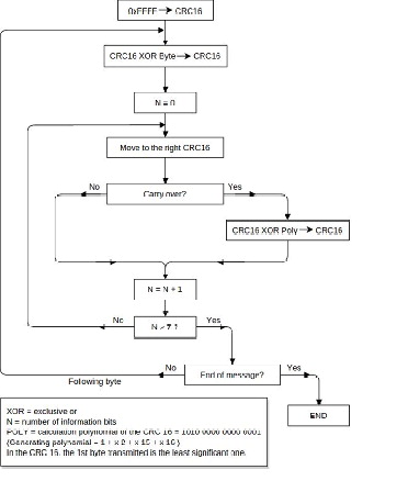
Calculation algorithm of the CRC16
Calculating CRC Checksum
1Initialize a 16 bit register (2 bytes) with 0xFFFF. This register is referred to as the CRC16 register.
2XOR-link the first byte of the message with the less significant byte of the CRC16 register. The result is saved in the CRC16 register.
3Move the CRC16 register 1 bit to the right (in the direction of the LSB), fill MSB with 0. Look at LSB.
4Check LSB value
- If the LSB was 0: Go to step 3 (move again).
- If the LSB was 1: XOR-link the CRC16 register with the CRC polynomial 0xA001 (1010 0000 0000 0001).
5Repeat steps 3 and 4 until eight movement operations have been carried out. When these have been carried out, a complete byte of the message will have been processed.
6Repeat steps 3 to 5 for the next byte of the message. Repeat everything until all bytes of the message have been processed.
7After the last byte, the CRC16 register contains the checksum.
8When the checksum is added to the message to be sent, then the two byes must be inverted as described below.
Adding CRC Checksum to the Message
If the 16 bit (2 bytes) CRC checksum is sent with a message, then the less significant byte is transferred before the more significant one.
For example, if the CRC checksum is 0x1241 (0001 0010 0100 0001): | ||||||||
Addr | Func | Data | Data | Data | Data | Data | CRC | CRC |
|
|
|
|
|
|
| 0x41 | 0x12 |
General
Abbreviations Used
AC | Alternating current |
| V | Voltage (volts) |
DC | Direct current |
| VA | Apparent power |
FW | Firmware |
| VAr | Reactive power |
PF | Power factor (cos j) |
| VMax | Maximum voltage |
PV | Photovoltaics |
| VMin | Minimum voltage |
RTC | Real-time clock |
| VRef | Reference voltage |
SF | Scale factor |
| W | Power (watts) |
SW | Software |
| IN | Inverter |
Abbreviations Used
AC | Alternating current |
| V | Voltage (volts) |
DC | Direct current |
| VA | Apparent power |
FW | Firmware |
| VAr | Reactive power |
PF | Power factor (cos j) |
| VMax | Maximum voltage |
PV | Photovoltaics |
| VMin | Minimum voltage |
RTC | Real-time clock |
| VRef | Reference voltage |
SF | Scale factor |
| W | Power (watts) |
SW | Software |
| IN | Inverter |
Communication with the Modbus Master
The Fronius Datamanager communicates with the Modbus master using register addresses in accordance with the SunSpec Alliance specifications.
(http://www.sunspec.org/)
NOTE!
The Fronius Datamanager also supports the integration of Fronius String Controls via Fronius Solar Net.
Fronius String Controls are displayed by an integrated Common Block and the subsequent String Combiner Model.
In addition, the Fronius Datamanager offers the option of providing via Modbus TCP data of an energy meter connected via Modbus RTU. The meter is displayed via an integrated Common Block and the subsequent Meter Model.
- For all devices:
- Common Block (1)
- For inverters:
- Fronius Register
- Inverter model (101, 102, 103, 111, 112, or 113)
- Inverter Controls:
- Nameplate (120)
- Basic Settings (121)
- Extended Measurements & Status (122)
- Immediate Controls (123) - Multiple MPPT Inverter Extension (160)
- Basic Storage Control (124) only available with Fronius Hybrid inverters
- For Fronius String Controls:
- String Combiner Model (403)
- For energy meters:
- Meter Model (201, 202, 203, 211, 212, or 213).
NOTE!
Only applies for Modbus RTU and only if no energy meter is connected:
If no data exchange takes place on the RS-485 bus, noise and interference may affect the lines.
In order for a receiver to remain in a defined status when there are no data signals, bias resistors should be used in order to maintain a defined idle state on the data lines.
The Fronius Datamanager does not have any bias resistors. Detailed information about the use of these resistors can be found in the document "MODBUS over serial line specification and implementation guide V1.02" (http://modbus.org/docs/Modbus_over_serial_line_V1_02.pdf).
Maps Register
Inverter |
| Fronius String Control |
| Energy Meter |
| Sensor Card |
SID |
| SID |
| SID |
| SID |
Common Block |
| Common Block |
| Common Block |
| Common Block |
Inverter Model |
| String Combiner Model |
| Meter Model |
| Irradiance Model |
Nameplate Model |
| End Block |
| End Block |
| Back of Module Temperature Model |
Basic Settings Model |
|
|
|
|
| Base Meteorological Model |
Ext. Measurement Model |
|
|
|
|
| End Block |
Immediate Controls Model |
|
|
|
|
|
|
Multi. MPPT Inv. Ext. Model |
|
|
|
|
|
|
Basic Storage Control (only in Fronius Hybrid inverter) |
|
|
|
|
|
|
End Block |
|
|
|
|
|
|
The register lists can be downloaded from the Fronius homepage:
https://www.fronius.com/de/downloads / Solar Energy / Modbus Sunspec Maps, State Codes und Events
Communication with the Modbus Master
Communication with the Modbus master takes place using register addresses in accordance with the SunSpec Alliance specifications.
(http://www.sunspec.org/)
The data of an energy meter connected via Modbus RTU can be made available via Modbus TCP or via Modbus RTU (second interface). The meter is displayed via an integrated Common Block and the subsequent Meter Model.
The allocation of register addresses to the corresponding function can be found in the following tables:- For all devices:
- Common Block (1)
- For inverters:
- Inverter Model (101, 102, 103, 111, 112 or 113)
- Inverter Controls:
- Nameplate (120)
- Basic Settings (121)
- Extended Measurements & Status (122)
- Immediate Controls (123) - Multiple MPPT Inverter Extension (160)
- Basic Storage Control (124)
- For energy meters:
- Meter Model (201, 202, 203, 211, 212 or 213)
NOTE!
Only applies for Modbus RTU and only if no energy meter is connected:
if no data exchange takes place on the RS-485 bus, noise and interference may affect the lines.
In order for a receiver to remain in a defined status when there are no data signals, bias resistors should be used in order to maintain a defined idle state on the data lines.
The Fronius Datamanager does not have any bias resistors. Detailed information about the use of these resistors can be found in the document "MODBUS over serial line specification and implementation guide V1.02" (http://modbus.org/docs/Modbus_over_serial_line_V1_02.pdf).
Response Times
The response times depend on factors such as the number of devices in the Fronius Solar Net ring. The higher the number of devices used, the longer the timeout for responses needs to be.
NOTE!
If there are several devices in the Fronius Solar Net ring, a timeout of at least 10 seconds should be used when querying inverter data.
Recommendation for timeout values
Modbus queries should only be executed sequentially and not in parallel. Execute the queries with a timeout of at least 10 seconds. Queries at millisecond intervals can lead to long response times. Multiple register queries in one message are faster than multiple queries of individual registers.
When using Fronius String Controls, a single Modbus request might result in two requests being sent via Fronius Solar Net; this can lead to longer response times than when using inverter requests. If Fronius String Controls are present, you should therefore use a higher timeout value for responses.
When first requesting common block data after restarting the Fronius Datamanager, the information about the Fronius String Control must first be requested using Fronius Solar Net. For this reason, this first request will take a little more time than subsequent requests.
If there are a larger number of devices in a Fronius Solar Net ring, it is advisable to split these between several Fronius Solar Net rings, which each have their own Fronius Datamanager, in order to speed up responses further. Fronius recommends operating a maximum of 6 inverters with a Datamanager.
Modbus Device ID for Inverters
The inverter's Modbus device ID is the same as its inverter number, which can be set using the control panel on the inverter.
(See the inverter operating instructions.)
NOTE!
There is only one exception to this rule:
The inverter number 00 converts to device ID 100 because Modbus reserves device ID 0 for broadcast messages.
Example: | |
Inverter number | Modbus device ID |
00 | 100 |
01 | 001 |
02 | 002 |
03 | 003 |
99 | 099 |
Modbus Device ID for Fronius String Controls
- its address in Fronius Solar Net
- a String Control offset value.
The default value for the String Control offset is 101 because the range reserved for inverters goes up to Modbus device ID 100.
The offset value can, however, be adjusted via the Fronius Datamanager web page.
=> see section "Data Output via Modbus"
| Example 1: String Control offset = 101 (standard value) | |
Fronius String Control address | Modbus device ID | |
0 | 101 | |
1 | 102 | |
2 | 103 | |
99 | 200 | |
A Fronius Solar Net Ring allows up to 100 inverters and up to 200 Fronius String Controls. The available Modbus device IDs are reserved for other functions (e.g., for energy meters) from 240.
With the standard String Control offset of 101, it would therefore not be possible to have Fronius String Control addresses from 139 (which corresponds to Modbus ID 240) upwards.
For this reason, it is possible to adjust the String Control offset on the Fronius Datamanager website if fewer than 100 inverters are being used.
| Example 2: 30 inverters, 200 Fronius String Controls, String Control offset = 40 | |
Fronius String Control address | Modbus device ID | |
0 | 40 | |
1 | 41 | |
2 | 42 | |
199 | 239 | |
Modbus Device ID for Energy Meters
If an energy meter (e.g., Fronius Smart Meter 63A) is connected to the Fronius Datamanager via Modbus RTU, it can be read out via the fixed Modbus device ID using Modbus TCP.
Fronius Smart Meter Address | Modbus Device ID | |
1 | 240 | |
2 | 241 | |
3 | 242 | |
4 | 243 | |
5 | 244 |
Modbus device ID for Fronius Sensor Cards
If a Fronius Sensor Card is connected to the Fronius Datamanager via Solar Net, it can be read out via a fixed Modbus device ID.
The Modbus device ID of a Fronius Sensor Card is derived from
- your address in the Fronius Solar Net
- the Sensor Card offset value 245
Fronius Sensor Card address | Modbus device ID | |
0 | 245 | |
1 | 246 | |
2 | 247 |
Event Flags
Status changes and faults in the inverters and Fronius String Controls are shown as event flags.
Detailed information and lists can be downloaded in various formats (xlsx, csv, json) from the Fronius website:
https://www.fronius.com/de/downloads / Solar Energy / Modbus SunSpec Maps, State Codes and Events
NOTE!
It is also possible to combine several state codes for one event.
For inverters:
An accurate description of the state codes can be found in the operating instructions of the relevant inverter.
If the inverter generates a state code, the relevant event flag is set in the Fronius Datamanager.
NOTE!
In addition, the relevant state code is also displayed in register F_Active_State_Code (214).
The event flag and state code will remain active for as long as the state code is displayed on the inverter. If another state code is generated, it will also be displayed in the event flags. In this case, there is a chance that the previous event flag will not be deleted.
It is therefore possible to manually delete the event flags and the state code
by entering 0xFFFF in register F_Reset_All_Event_Flags (215).
Register addresses
IMPORTANT!
- Register addresses do not remain constant.
- The actual register addresses depend on the composition of the dynamic SunSpec register list.
Correct procedure:
- Search for the model by making a request (determine start address)
- Then work with offsets
To read a register, the register's start address must be specified in the Modbus request.
Fronius Basic Register: 212
SunSpec Basic Register: 40001
Registers begin at 1 and do not represent a function code.
Do not confuse the registers with the Modicon address scheme:
In the Modicon address scheme, 40001 is displayed as 4x40001.
To read register 40001, use address 40000 (0x9C40).
The register address that is output therefore always has 1 number less than the actual register number.
NOTE!
The lengths of individual models may vary due to the data types used.
Start addresses are therefore specified for SunSpec models in the case of some register tables.
This start address, together with the offset from the table, then produces the value of the actual register number.
Example: Table Nameplate Model (120) on page (→):
The register WRtg of the nameplate model has an offset of 4. The start address is specified as 40131 with the setting "float".
Therefore, the correct register number is: 40131 + 4 = 40135.
Examples for Modbus RTU:
| 1. Request for four registers starting from register 40005 (Mn, Manufacturer) | |||||||||||||
Send (bytes in hexadecimal) | ||||||||||||||
01 | 03 | 9C | 44 | 00 | 04 | 2A | 4C |
| ||||||
Device ID | Function code | Address 40004 (corresponds to | Number of registers to be read | Checksum |
| |||||||||
Low byte | High byte |
| ||||||||||||
|
|
|
|
|
|
|
|
|
|
|
|
|
| |
Receive (bytes in hexadecimal) |
| |||||||||||||
01 | 03 | 08 | 46 | 72 | 6F | 6E | 69 | 75 | 73 | 00 | 8A | 2A |
| |
Device ID | Function code | Number of bytes | Address 40005 | Address 40006 | Address 40007 | Address 40008 | Checksum |
| ||||||
Low byte | High byte |
| ||||||||||||
| 2. Enter one register starting from register 40242 (WmaxLimPct) | |||||||||||||
01 | 10 | 9D | 32 | 00 | 01 | 02 | 13 | 88 | E3 | DD | ||||
Device ID | Function code | Address 40242 | Number of registers to be entered | Number of data bytes still to follow | Register value to be entered 0x1388 = 5000 | Checksum | ||||||||
| Low byte | High byte | ||||||||||||
|
|
|
|
|
|
|
|
|
|
|
|
|
| |
01 | 10 | 9D | 32 | 00 | 01 | 8F | AA |
| ||||||
Device ID | Function code | Address 40242 | Number of registers entered | Checksums | 40008 |
|
| |||||||
Low byte | High byte |
| ||||||||||||
Examples for Modbus TCP:
| 1. Request for four registers starting from register 40005 (Mn, Manufacturer) | |||||||||||
Send (bytes in hexadecimal) | ||||||||||||
MBAP header | 03 | 9C | 44 | 00 | 04 |
| ||||||
For details, see description of MBAP header | Function code | Address 40004 (corresponds to | Number of registers to be read |
| ||||||||
| ||||||||||||
| ||||||||||||
Receive (bytes in hexadecimal) | ||||||||||||
MBAP header | 03 | 08 | 46 | 72 | 6F | 6E | 69 | 75 | 73 | 00 | ||
For details, see description of MBAP header | Function code | Number of bytes | Address 40005 | Address 40006 | Address 40007 | Address 40008 | ||||||
| 2. Enter one register starting from register 40242 (WmaxLimPct) | |||||||||||
MBAP header | 10 | 9D | 32 | 00 | 01 | 02 | 13 | 88 | ||||
For details, see description of MBAP header | Function code | Address 40242 | Number of registers to be entered | Number of data bytes still to follow | Register value to be entered 0x1388 = 5000 | |||||||
| ||||||||||||
MBAP header | 10 | 9D | 32 | 00 | 01 | |||||||
For details, see description of MBAP header | Function code | Address 40242 | Number of registers entered | |||||||||
Unavailable data records
| Fronius inverters cannot always provide all the data specified in the SunSpec data models. Depending on the data type, this data is represented by the following values in accordance with the SunSpec specification: | |
| 0x80001) | |
1) The prefix "0x" stands for hexadecimal numbers.
NOTE!
Data points that are not supported are marked with "Not supported" in the "Range of values" column in the register tables.
In this case, during reading, the corresponding value from the list above is obtained depending on the data type.
In certain instances, registers which are basically listed as supported may also return this value. This is because some values depend on the device type, e.g., currents AphB and AphC in the case of a single-phase inverter.
Time Response of the Supported Operating Modes
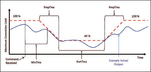
Time Response Illustrated by Power Reduction
Three possible time values are shown in the figure "Time response illustrated by power reduction":
- WinTms 0–300 [seconds]
Specifies a time window in which the operating mode is randomly started. The time window starts when the start command for the operating mode is issued (e.g., OutPFSet_Ena = 1).
WinTms can be used to prevent all the inverters in the system from applying the changes at the same time. If the time window is set to 0 (the default value), the operating mode will start immediately. - RvrtTms 0–28800 [seconds]
Determines how long the operating mode will remain active. The timer is restarted with every Modbus message received. If no new Modbus message was received during the fallback time (= RvrtTms), the operating mode is automatically ended and the operating mode with the next highest priority (Datamanager web interface - Settings - UC Editor) becomes active, e.g., dynamic power reduction. If RvrtTms is 0 (the default value), the operating mode remains active until it is manually deactivated via the corresponding register. In this instance the fallback option is not available. - RmpTms (supported from version 1.11.3-2 (Hybridmanager) / 3.13.3-2 (Datamanager))
Specifies how quickly the changes are to be made. The corresponding value gradually changes during the specified time period from the old to the new value.
If RmpTms is 0 (the default value) or if this value is not supported, the new value will be valid immediately.
Sign Convention for the Power Factor
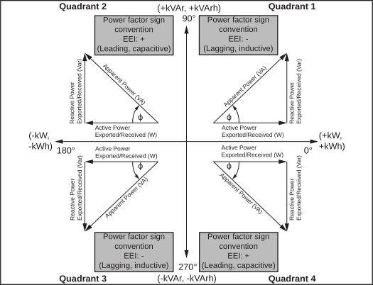
The EEI sign convention1) for the power factor is in line with the SunSpec specification and is based on the information contained in the "Handbook for Electricity Metering" and IEC 61557-12 (2007).
The power factor is:- negative if the reactive power is positive (over-excited, quadrant 1)
- positive if the reactive power is negative (under-excited, quadrant 4)
1) EEI = Edison Electrical Institute
Values Saved on the Card
- WRtg
AC nominal output of inverter. - VARtg
AC nominal apparent output of inverter.
Default value = WRtg - VArRtgQ1
Maximum AC reactive power in the first quadrant (over-excited).
Default value is calculated based on the available cos Phi (0.85) and the nominal apparent power. Note the scaling factor VArRtg_SF. - VArRtgQ4
Maximum AC reactive power in the fourth quadrant (under-excited).
Default value is calculated based on the available cos Phi (0.85) and the nominal apparent power. Note the scaling factor VArRtg_SF. - ARtg
AC nominal current of inverter.
- WMax
Maximum AC power
Default value = WRtg - VRef
Reference voltage at the feed-in point - VRefOfs
Deviation from reference voltage - VMax
Maximum AC voltage - VMin
Minimum AC voltage - VAMax
Maximum AC apparent power
Default value = VARtg
Saving Values
If data is not available or is incorrectly displayed, the values listed above can be adjusted and saved on the Datamanager.
Changes currently have no influence on the way the Datamanager or the inverters function and are merely used to display device-specific information.
In order to save the values, the register F_Store_Data (213) of any inverter must be written with 0xFFFF. The values for all inverters are then permanently saved and are also available after an AC reset of the Datamanager.
Deleting Values
It is only possible to delete values for an individual inverter. To do this, enter 0xFFFF into the register F_Delete_Data (212) of the relevant inverter.
Scale Factors
IMPORTANT! Scale factors (also possible when selecting “Float”!) are not static, even if they are entered as a fixed value in these Operating Instructions.
Scale factors can change every time the firmware is changed (e.g., scale factor for power specification).
Scale factors with constant values are listed in the tables in the column “Range of values”.
Current data (data of inverters, Fronius String Controls, and energy meters) may have variable scale factors. These must be read from the corresponding registers.
The data type "sunssf" is a signed integer with 16 bits.
Example calculation:
(Model 160): 1_DCW = 10000, DCW_SF = -1 -> Power = 10000 x 10^(-1) = 1000 W
Non-writable registers
- Read-only (R) registers
- Registers which are currently not supported
NOTE!
If an attempt is made to write to such registers, the inverter does not return an exception code!
The values written to these registers are ignored without an error message.
In Model 123 and 124, an exception occurs during write access if the control option in the local web interface has been deactivated.
Entering Invalid Values
Some registers only permit certain values. The valid values can be found in the relevant register table.
If an invalid value is entered into a register, the inverter control will return exception code 3 (illegal data value). The invalid value is ignored.
Modbus Settings
General
From your web browser, you can use the Fronius Datamanager web interface to apply the Modbus connection settings which cannot be accessed via the Modbus protocol.
NOTE!
It is not necessary to use a web interface when transferring data via Modbus RTU since Modbus RTU is enabled at the factory, except for Symo Hybrid.
General
From your web browser, you can use the Fronius Datamanager web interface to apply the Modbus connection settings which cannot be accessed via the Modbus protocol.
NOTE!
It is not necessary to use a web interface when transferring data via Modbus RTU since Modbus RTU is enabled at the factory, except for Symo Hybrid.
Opening the Modbus Settings
1Install Fronius Datamanager
=> see the Fronius Datamanager operating instructions.
=> see the Fronius Datamanager operating instructions.
2Open Internet browser
3Enter the following in the address field of the Internet browser:The web interface's start page is displayed.
- the IP address of the Fronius Datamanager (can be accessed via System Information)
- or host name and domain name of the Fronius Datamanager.
4Select the "Settings" section (1).
5Open the "Modbus" section (2).
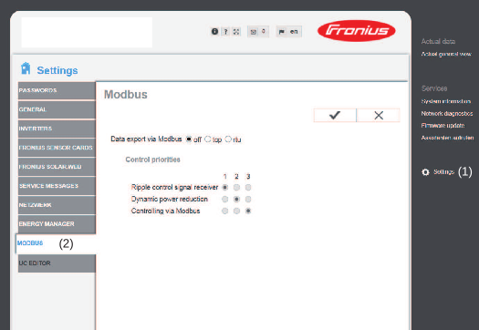
NOTE!
In the case of Fronius Datamanager 2.
0, the "Data output via Modbus" is set to rtu in the factory.
The rtu option is not available for the Datamanager 1.
Open the Modbus settings
1Open the web interface of the inverter
2Select the "Communication" section (1)
3Open the "Modbus" menu item (2)
Data Output via Modbus
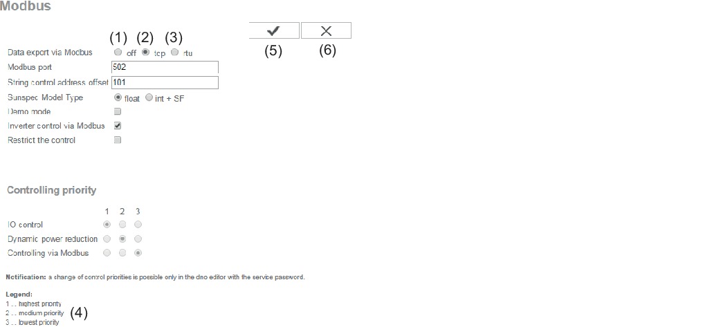
| Data Output via Modbus The Modbus rtu transmission protocol is only available for Fronius Datamanager 2.0. |
Note! If there is a Modbus energy meter (e.g., Fronius Smart Meter) configured under Settings/Meter on the system, it will not be possible to use the "rtu" setting. In this case, data output via Modbus will be deactivated automatically upon selection of "rtu." This change will only be visible once the Datamanager website has been reloaded.
Any energy meter connected via RS485 can also be read by Modbus TCP via the corresponding SunSpec models. The Modbus ID for the meter is 240.
(1) | off If the data output via Modbus is deactivated, control commands sent to the inverter via Modbus are reset, e.g., no power reduction or no reactive power specification. |
(2) | tcp |
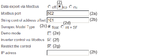 | |
(2a) | Modbus port Presetting: 502 |
(2b) | String Control address offset |
| SunSpec Model Type |
(2c) | float |
(2d) | int+SF |
| IMPORTANT! Since the different models have different numbers of registers, the register addresses of all the subsequent models also change when the data type is changed. |
(2e) | Demo mode |
(2f) | Inverter control via Modbus If this option is activated, the inverter can be controlled via Modbus. The "Restrict the control" selection field is displayed. Inverter control includes the following functions:
|
(3) | rtu |
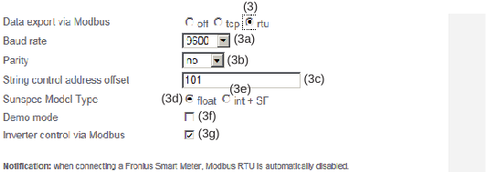 | |
(3a) | Baud rate |
(3b) | Parity |
(3c) | String Control address offset |
| SunSpec model type |
(3d) | float |
(3e) | int+SF |
| IMPORTANT! Since the different models have different numbers of registers, the register addresses of all the subsequent models also change when the data type is changed. |
(3f) | Demo mode |
(3g) | Inverter control via Modbus If this option is activated, the inverter is controlled via Modbus. Inverter control includes the following functions:
|
(4) | Controlling priority 1 = highest priority, 3 = lowest priority. The control priorities can only be changed in the UC EDITOR menu item. |
(5) | "Apply/Save" button |
(6) | "Cancel/Discard entries" button |
Limiting control
The "Limit Control" option is only available for the TCP transmission protocols.
It is used to block inverter control commands from unauthorized users by only permitting control for specific devices.
Limit Control
If this option is activated, only certain devices will be able to send control commands.
IP address
To limit inverter control to one or more devices, enter the IP addresses of the devices which are permitted to send commands to the inverter in this field. Multiple entries are separated by commas.
- One IP address: 98.7.65.4
- Control only permitted by IP address 98.7.65.4
- Control only permitted by IP address 98.7.65.4
- Several IP addresses: 98.7.65.4,222.44.33.1
- Control only permitted by IP addresses 98.7.65.4 and 222.44.33.1
- Control only permitted by IP addresses 98.7.65.4 and 222.44.33.1
- IP address range, e.g., from 98.7.65.1 to 98.7.65.254 (CIDR notation): 98.7.65.0/24
- Control only permitted by IP addresses 98.7.65.1 to 98.7.65.254
Save or Reject Changes
 Saves the changes and displays a message confirming this.
If you exit the Modbus section without saving your changes, all the changes you have made will be rejected.
 Prompts you to confirm whether or not you wish to reject the changes you have made and then reinstates the most recently saved values.
Fronius Registers
Fronius Register
These registers only apply to inverters. These registers are not relevant to Fronius String Controls and energy meters.
The Register tables can be found on the Fronius homepage or opened using the link:
http://www.fronius.com/QR-link/0006
Fronius Register
These registers only apply to inverters. These registers are not relevant to Fronius String Controls and energy meters.
The Register tables can be found on the Fronius homepage or opened using the link:
http://www.fronius.com/QR-link/0006
Inverter Status Code
Register F_Active_State_Code (214) displays the inverter status code which has just been generated. This may also be displayed on the inverter’s display. This code is also displayed as an event flag in the inverter model. The displayed code remains active for as long the inverter has the corresponding status. Alternatively, the status can also be deleted by using register F_Reset_All_Event_Flags.
Deleting Event Flags and Status Codes
The event flags in the inverter models (101, 102, 103 and 111, 112, 113) remain active until the corresponding status is no longer present on the inverter. There are a few exceptional cases in which the event flags are not deleted. For this reason, it is possible to reset the event flags and the displayed status code by issuing the Modbus command.
1Enter 0xFFFF in register F_Reset_All_Event_Flags (215)
- F_Active_State_Code (214)
- Evt1
- Evt2
- EvtVnd1 to EvtVnd4
Saving and Deleting Data
If the value 0xFFFF is written in the register F_Store_Data (213), then all nominal values (ratings) for all inverters are saved on the Fronius Datamanager. These values can be changed in the corresponding registers of the Nameplate Model and the Basic Settings Model. This can be useful if, for example, no nominal values could be automatically determined for a device and you want to enter the values manually.
If you want to delete the saved values for a particular inverter, you must write the value 0xFFFF in the F_Delete_Data (212) register. The values are then only deleted for this inverter. The deletion can only ever be applied to the inverter with which there is currently communication.
Changing the Data Type
The data type for the data models for inverters and energy meters can be selected via the F_ModelType (216) register. It is possible to select either display as floating point numbers (float, standard) or as integers with scale factors (int+SF).
NOTE!
This setting only relates to the inverter model (inverter) and the meter model (energy meter).
All other models continue to use integers and scale factors.
This setting functions in the same way as the web interface Modbus settings – SunSpec model type.
- Float = 1 (standard): Inverter model 111, 112, or 113; meter model 211, 212, or 213
- int+SF = 2: Inverter model 101, 102, or 103; meter model 201, 202, or 203.
NOTE!
Since the different models have different numbers of registers, the register addresses of all the subsequent models also change when the data type is changed.
NOTE!
To avoid accidental changes, writing a value to setting F_ModelType must be confirmed by writing value 0x06 to the same register immediately after writing the type.
If the confirmation is omitted, changes will be reset after a few seconds.
System Totals
These values are displayed in Watt (W) or Watt hours (Wh) and do not require scale factors.
- F_Site_Power (500–501): Power
- F_Site_Energy_Day (502–505): Daily Energy
- F_Site_Energy_Year (506–509): Yearly Energy
- F_Site_Energy_Total (510–513): Total energy of the entire system.
Common & Inverter Model
Common Block Register
The description of the Common Block including the SID register (register 40001–40002) for identification as a SunSpec device applies for each device type (inverter, Fronius String Control, energy meter). Each device has its own Common Block, which lists information about the device (model, serial number, SW version, etc.).
The Register tables can be found on the Fronius homepage or opened using the link:
http://www.fronius.com/QR-link/0006
Common Block Register
The description of the Common Block including the SID register (register 40001–40002) for identification as a SunSpec device applies for each device type (inverter, Fronius String Control, energy meter). Each device has its own Common Block, which lists information about the device (model, serial number, SW version, etc.).
The Register tables can be found on the Fronius homepage or opened using the link:
http://www.fronius.com/QR-link/0006
Inverter Model Register
- the default set inverter model with floating point display
(setting "float"; 111, 112 or 113) - the inverter model with integers and scaling factors
(setting "int+SF"; 101, 102 or 103)
The register number of the two model types is different!
The Register tables can be found on the Fronius homepage or opened using the link:
http://www.fronius.com/QR-link/0006
SunSpec Operating Codes
Name | Value | Description |
|---|---|---|
I_STATUS_OFF | 1 | Inverter is off |
I_STATUS_SLEEPING | 2 | Auto shutdown |
I_STATUS_STARTING | 3 | Inverter starting |
I_STATUS_MPPT | 4 | Inverter working normally |
I_STATUS_THROTTLED | 5 | Power reduction active |
I_STATUS_SHUTTING_DOWN | 6 | Inverter shutting down |
I_STATUS_FAULT | 7 | One or more faults present, see St*or Evt* register |
I_STATUS_STANDBY | 8 | Standby |
| * | Inverter model register |
Fronius Operating Codes
Name | Value | Description |
|---|---|---|
I_STATUS_OFF | 1 | Inverter is off |
I_STATUS_SLEEPING | 2 | Auto shutdown |
I_STATUS_STARTING | 3 | Inverter starting |
I_STATUS_MPPT | 4 | Inverter working normally |
I_STATUS_THROTTLED | 5 | Power reduction active |
I_STATUS_SHUTTING_DOWN | 6 | Inverter shutting down |
I_STATUS_FAULT | 7 | One or more faults present, see St*or Evt* register |
I_STATUS_STANDBY | 8 | Standby |
I_STATUS_NO_BUSINIT | 9 | No SolarNet communication |
I_STATUS_NO_COMM_INV | 10 | No communication with inverter possible |
I_STATUS_SN_OVERCURRENT | 11 | Overcurrent detected on SolarNet plug |
I_STATUS_BOOTLOAD | 12 | Inverter is currently being updated |
I_STATUS_AFCI | 13 | AFCI event (arc detection) |
| * | Inverter model register |
Nameplate Model (120)
General
- DERType (3)
Type of device. The register returns the value 4 (PV device). - WRtg (4)
Nominal power of inverter. - VARtg (6)
Nominal apparent power of inverter. - VArRtgQ1 (8) – VArRtgQ4 (11)
Nominal reactive power values for the four quadrants. - ARtg (13)
Nominal current of inverter. - PFRtgQ1 (15) – PFRtgQ4 (18)
Minimal power factor values for the four quadrants.
General
- DERType (3)
Type of device. The register returns the value 4 (PV device). - WRtg (4)
Nominal power of inverter. - VARtg (6)
Nominal apparent power of inverter. - VArRtgQ1 (8) – VArRtgQ4 (11)
Nominal reactive power values for the four quadrants. - ARtg (13)
Nominal current of inverter. - PFRtgQ1 (15) – PFRtgQ4 (18)
Minimal power factor values for the four quadrants.
Nameplate Register
- for "float" setting: 40131
- for "int+SF" setting: 40121
The Register tables can be found on the Fronius homepage or opened using the link:
http://www.fronius.com/QR-link/0006
Basic Settings Model (121)
Basic Settings Register
- for "float" setting: 40159
- for "int+SF" setting: 40149
The Register tables can be found on the Fronius homepage or opened using the link:
http://www.fronius.com/QR-link/0006
Basic Settings Register
- for "float" setting: 40159
- for "int+SF" setting: 40149
The Register tables can be found on the Fronius homepage or opened using the link:
http://www.fronius.com/QR-link/0006
Reference Voltage
VRef (4)
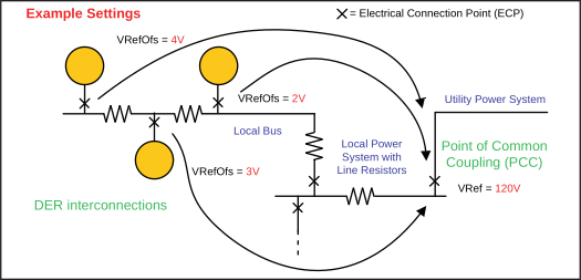
The reference voltage is the voltage at the joint connection point where the local grid is connected to the public grid. The reference voltage is the same as the inverter's nominal voltage.
=> See figure "Joint Connection Point."
The value is given in volts in the range of 0 (0x0000) to 400 (0x0190).
Joint Connection Point
Deviation from Reference Voltage
VRefOfs (5)
Depending on the wiring of the local grid, there may be a deviation from the reference voltage at the point where each individual inverter is connected to the local grid (see "Joint connection point" diagram).
The value is given in volts in the range of -20 (0xFFEC) to 20 (0x0014).
Extended Measurements & Status Model (122)
General
- PVConn (3)
This bit field displays the inverter's status- Bit 0: Connected
- Bit 1: Responsive
- Bit 2: Operating (inverter feeds energy in)
- ECPConn (5)
This register displays the status of connection to the grid- ECPConn = 1: Inverter is currently feeding power into the grid
- ECPConn = 0: Inverter is not feeding power into the grid
- ActWH (6–9)
Active energy meter - StActCtl (36–37)
Bit field for currently active inverter modes- Bit 0: Power reduction (FixedW; corresponds to WMaxLimPct specification)
- Bit 1: Constant reactive power specification (FixedVAR; corresponds to VArMaxPct)
- Bit 2: Setting a constant power factor (FixedPF; corresponds to OutPFSet)
- TmSrc (38–41)
Source for the time synchronization, the register returns the string "RTC" - Tms (42–43)
Current time and date of the RTC
The seconds are specified from January 1, 2000 00:00 (UTC) to the current time.
General
- PVConn (3)
This bit field displays the inverter's status- Bit 0: Connected
- Bit 1: Responsive
- Bit 2: Operating (inverter feeds energy in)
- ECPConn (5)
This register displays the status of connection to the grid- ECPConn = 1: Inverter is currently feeding power into the grid
- ECPConn = 0: Inverter is not feeding power into the grid
- ActWH (6–9)
Active energy meter - StActCtl (36–37)
Bit field for currently active inverter modes- Bit 0: Power reduction (FixedW; corresponds to WMaxLimPct specification)
- Bit 1: Constant reactive power specification (FixedVAR; corresponds to VArMaxPct)
- Bit 2: Setting a constant power factor (FixedPF; corresponds to OutPFSet)
- TmSrc (38–41)
Source for the time synchronization, the register returns the string "RTC" - Tms (42–43)
Current time and date of the RTC
The seconds are specified from January 1, 2000 00:00 (UTC) to the current time.
Extended Measurements & Status Register
- for "float" setting: 40191
- for "int+SF" setting: 40181
The Register tables can be found on the Fronius homepage or opened using the link:
http://www.fronius.com/QR-link/0006
Immediate Control Model (123)
General
- deactivation of inverter's grid power feed operation (standby)
- constant reduction of output power
- specification of a constant power factor
- specification of a constant relative reactive power
In the settings on the inverter's web interface, the setting "Inverter control via Modbus" must be enabled under Modbus for write functions to be possible. Depending on the control priority that has been set (IO control, dynamic power reduction, or control via Modbus), Modbus commands may not be accepted.
General
- deactivation of inverter's grid power feed operation (standby)
- constant reduction of output power
- specification of a constant power factor
- specification of a constant relative reactive power
In the settings on the inverter's web interface, the setting "Inverter control via Modbus" must be enabled under Modbus for write functions to be possible. Depending on the control priority that has been set (IO control, dynamic power reduction, or control via Modbus), Modbus commands may not be accepted.
Immediate Controls Register
- for "float" setting: 40237
- for "int+SF" setting: 40227
The Register tables can be found on the Fronius homepage or opened using the link:
http://www.fronius.com/QR-link/0006
Standby
Conn_WinTms (3) to Conn (5)
These registers are used to control the standby mode (no grid power feed operation) of the inverter.
Conn_WinTms (3) and Conn_RvrtTms (4)
These registers can be used to control the inverter's time response. => See section "Time Response of the Supported Operating Modes".
0 is set as the default for all registers.
Register Conn indicates whether or not the inverter is currently feeding power into the grid (0 = standby, 1 = grid power feed operation).
- In order to switch the inverter to standby, enter the value 0 into this register.
- In order to reactivate the inverter, enter the value 1 into this register.
NOTE!
To find out whether or not the inverter is feeding power into the grid, you can also use the ECPConn register and check the extended measurements and status model.
Power reduction
WMaxLimPct (6) to WMaxLim_Ena (10)
These registers can be used to set an output power reduction in the inverter.
WMaxLimPct (6)
In register WMaxLimPct you can enter values between 0% and 100%. Depending on the inverter’s software version, values below 10 may force the inverter into standby (no grid power feed operation).
The values limit the device’s maximum possible output power and therefore may not necessarily affect the real-time power.
IMPORTANT! Observe the scale factor for this register.
Further information can be found at:
http://sunspec.org/wp-content/uploads/2015/06/SunSpec-Information-Models-12041.pdf
WMaxLimPct_WinTms (7), WMaxLimPct_RvrtTms (8)
These registers can be used to control the inverter’s time response for this operating mode. => See section “Time Response of the Supported Operating Modes.”
0 is set as the default for all registers.
Used to start and end this operating mode
- Enter value 1 into register WMaxLim_Ena = start operating mode
- Enter value 0 into register WMaxLim_Ena = end operating mode
NOTE!
Proceed as follows to change values when an operating mode is active (e.
g., when setting a different power limit or return time):
Enter the new value into the relevant register
Restart the operating mode using register WMaxLim_Ena
Example:
Setting a Power Reduction
If you are working with function code 0x10 (write multiple registers), performance specifications can be used to achieve a higher level of performance. Instead of using two Modbus commands, it is now possible to preset both the power and enable at the same time with just one command. All 5 registers (WMaxLimPct, WMaxLimPct_WinTms, WMaxLimPct_RvrtTms, WMaxLimPct_RmpTms, WMaxLim_Ena) can be written with one command. Writing to the non-supported "Read Only" register WMaxLimPct_RmpTms takes place without returning an otherwise usual exception (error) code.
For example, register values for 80% specification without timing specification: 8000, 0, 0, 0, 1
1Enter the value for the output power reduction in register WMaxLimPct
(e.g., 30 for 30%).
(e.g., 30 for 30%).
2As an option, you can set the start and return time using registers WMaxLimPct_WinTms and WMaxLimPct_RvrtTms.
3Start the operating mode by entering 1 in register WMaxLim_Ena.
IMPORTANT! Observe the scale factor for this register.
Further information can be found at:
http://sunspec.org/wp-content/uploads/2015/06/SunSpec-Information-Models-12041.pdf
Example:
Changing the Return Time When Power Reduction Has Been Activated
If the power reduction was originally started using WMaxLimPct_RvrtTms = 0, the operating mode must be manually deactivated.
1Set WMaxLimPct_RvrtTms to 30, for example
2Apply the change by entering 1 in register WMaxLim_Ena
- The operating mode is automatically deactivated after 30 seconds and the mode with the next highest priority becomes active (e.g., dynamic power reduction)
Effects of Reactive Power Specifications on Effective Power
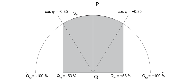
- Fronius Galvo cos phi = 0.85, VArrel = 53%
- Fronius Symo cos phi = 0.7, VArrel = 71%.
NOTE!
Due to the current technical conditions, only a cos phi up to a maximum of ±0.
80 can be specified per Modbus. In some circumstances, however, VArrel specifications may demand a lower value.
The following diagram shows the possible working area of the inverter. All valid operating points defined by effective power P and reactive power Q are within the gray area.
Under-excited (inductive) | Over-excited (capacitive) | ||
 | |||
Legend: | ||||
W | Power |
| VArmax | Nominal reactive power |
Wmax | Nominal power |
| VArrel | Relative reactive power |
Constant Power Factor
OutPFSet (11) to OutPFSet_Ena (15)
These registers can be used to set a constant power factor in the inverter.
- In register OutPFSet it is possible to enter both positive and negative values for the power factor.
- The values must be scaled up by the factor in register OutPFSet_SF.
- The lowest possible values depend on the inverter type and can be found in the Nameplate Model.
NOTE!
The power factor value must be entered with the correct sign, see section "Sign Convention for the Power Factor"
positive for under-excited
negative for over-excited.
OutPFSet_WinTms (12), OutPFSet_RvrtTms (13)
These registers can be used to control the inverter's time response for this operating mode. => See section "Time Response of the Supported Operating Modes".
0 is set as the default for all registers.
Used to start and end this operating mode
- Enter value 1 into register OutPFSet_Ena = start operating mode
- Enter value 0 into register OutPFSet_Ena = end operating mode.
NOTE!
Proceed as follows to change values when an operating mode is active (e.g., when setting a different power factor or return time):
Enter the new value into the relevant register
Restart the operating mode using register OutPFSet_Ena.
Example:
Setting a Constant Power Factor
1Enter the power factor value in register OutPFSet
(e.g., 950 for 0.95).
(e.g., 950 for 0.95).
2As an option, you can set the start and return time using registers OutPFSet_WinTms and OutPFSet_RvrtTms.
3Start the operating mode by entering 1 in register OutPFSet_Ena.
Constant Relative Reactive Power
VArMaxPct (17) to VArPct_Ena (23)
These registers can be used to set on the inverter a constant value for the reactive power to be produced by the inverter.
- Used to set a value for constant reactive power.
- The minimum and maximum limits depend on the type of inverter.
NOTE!
In practical operation, the reactive power that is actually available is specified by the inverter's operating limits.
For this reason, the reactive power specification can only be reached if enough effective power is fed into the grid.
If too little effective power is fed into the grid, the inverter will operate at its operating limit.
VArPct_WinTms (19), VArPct_RvrtTms (20)
These registers can be used to control the inverter's time response for this operating mode. => See section "Time Response of the Supported Operating Modes".
0 is set as the default for all registers.
- This register cannot be changed.
- It returns the (currently) supported operating mode.
Reactive power as a percentage of the maximum possible reactive power.
Used to start and end this operating mode
- Enter value 1 into register VArPct_Ena = start operating mode
- Enter value 0 into register VArPct_Ena = end operating mode.
NOTE!
Proceed as follows to change values when an operating mode is active (e.
g., when setting a different reactive power value or return time):
Enter the new value into the relevant register.
Restart the operating mode using register VArPct_Ena.
Example:
Setting Constant Reactive Power
1Enter the relative reactive power value in register VArMaxPct
(e.g., 80 for 80%).
(e.g., 80 for 80%).
2As an option, you can set the start and return time using registers VArPct_WinTms and VArPct_RvrtTms.
3Start the operating mode by entering 1 in register VArPct_Ena.
Multiple MPPT Inverter Extension Model (160)
General
The Multiple MPPT Inverter Extension Model contains the values of up to two DC inverter inputs.
If the inverter has two DC inputs, then this is where the current, voltage, power, energy, and status codes for the individual inputs are listed. In the inverter model (101–103 or 111–113), only the full DC power of both inputs is output in this case. DC current and DC voltage are displayed as “not implemented”.
If the inverter only has one DC input, all values for the second string are set to “not implemented” (from register 2_DCA). The description of the second input (register 2_IDStr) appears as “not supported” in this case. The values for the first (and only) input are displayed normally.
General
The Multiple MPPT Inverter Extension Model contains the values of up to two DC inverter inputs.
If the inverter has two DC inputs, then this is where the current, voltage, power, energy, and status codes for the individual inputs are listed. In the inverter model (101–103 or 111–113), only the full DC power of both inputs is output in this case. DC current and DC voltage are displayed as “not implemented”.
If the inverter only has one DC input, all values for the second string are set to “not implemented” (from register 2_DCA). The description of the second input (register 2_IDStr) appears as “not supported” in this case. The values for the first (and only) input are displayed normally.
Multiple MPPT Inverter Extension Register
- for "float" setting: 40263
- for "int+SF" setting: 40253
The Register tables can be found on the Fronius homepage or opened using the link:
http://www.fronius.com/QR-link/0006
Start Offset | End Offset | Size | R/W | Function codes | Name | Type | Units | Scale factor | Description | Range of values |
40 | 40 | 1 | R | 0x03 | 2_DCA | uint16 | A | DCA_SF | DC Current | 1) |
41 | 41 | 1 | R | 0x03 | 2_DCV | uint16 | V | DCV_SF | DC Voltage | 1) |
42 | 42 | 1 | R | 0x03 | 2_DCW | uint16 | W | DCW_SF | DC Power | 1) |
1) | Total values DCW = Total DC power In hybrid systems: When discharging the storage: DCW = 1_DCW + 2_DCW Examples | |||||||||
| a) | PV input: | 2000 W production ==> | 1_DCW = 2000 W | ||||||
|
| Storage: | 1000 W discharge ==> | 2_DCW = 1000 W | ||||||
|
| DCW = 1_DCW + 2_DCW = 1000 W + 2000 W = 3000 W | ||||||||
| b) | PV input: | 2000 W production ==> | 1_DCW = 2000 W | ||||||
|
| Storage: | - 1000 W charge ==> | 2_DCW = 1000 W | ||||||
|
| DCW = 1_DCW + 2_DCW = 2000 W + (- 1000 W) = 1000 W | ||||||||
Basic Storage Control Model (124)
General
This model is only available for inverters with a storage solution.
The Basic Storage Control Model can be used to make the following settings on the inverter:
- Setting a power window within which the charge/discharge capacity of the energy storage may fluctuate.
- Setting a minimum charge level that the energy storage must not fall below.
- Permitting/preventing grid charging of the energy storage.
NOTE!
All specifications are to be considered recommendations.
The inverter may deviate from the specifications if this is necessary for operational safety reasons.
General
This model is only available for inverters with a storage solution.
The Basic Storage Control Model can be used to make the following settings on the inverter:
- Setting a power window within which the charge/discharge capacity of the energy storage may fluctuate.
- Setting a minimum charge level that the energy storage must not fall below.
- Permitting/preventing grid charging of the energy storage.
NOTE!
All specifications are to be considered recommendations.
The inverter may deviate from the specifications if this is necessary for operational safety reasons.
Information Provided
The Basic Storage Control Model provides the following read-only information:
WChaMax
- If energy storage is available, this register feeds back the baseline value for the registers OutWRte and InWRt.
WChaMax := max(MaxChaRte, MaxDisChaRte) - If energy storage is not available, the register feeds back a value of 0.
ChaState
- Energy storage charge level in %:
Estimated_Capacity_Remaining [Wh] / Estimated_Capacity_Maximum [Wh]
ChaSt
Energy storage operating status
- OFF: Energy storage is not available
- EMPTY: Energy storage is currently fully discharged
- DISCHARGING: Energy storage is in the process of being discharged
- CHARGING: Energy storage is in the process of being charged
- FULL: Energy storage is currently fully charged
- HOLDING: Energy storage is currently neither charged nor discharged
- TESTING: used during calibration or service charge
Power Window Specifications
In the settings on the inverter's web interface, the setting "Inverter control via Modbus" must be enabled under Modbus for write functions to be possible. Depending on the control priority that has been set (IO control, dynamic power reduction, or control via Modbus), Modbus commands may not be accepted.
The following examples assume that WchaMax = 3300 W.
The following applies for the resulting power windows:
- Negative power values indicate that the energy storage is charging
- Positive values indicate that the energy storage is discharging
NOTE!
The values in the following examples must be scaled according to their scale factors in the specified scale registers after reading and before writing.
Manipulating the registers InWRte, OutWRte and StorCtl_Mod will generate changes in the battery status in Fronius Solar.web, ex: Forced Recharge and Energy saving mode, depending on user settings and current status of the battery.
Example 1: Only permit energy storage charging
This behavior can be achieved by limiting the maximum discharge capacity to 0% => results in window [-3300 W, 0 W]
- OutWRte = 0% (set discharge limit of WchaMax to 0%)
- StorCtl_Mod = 2 (activates discharge limit, bit pattern: 10)
- InWRte is not relevant in this case
Example 2: Only permit energy storage discharging
This behavior can be achieved by limiting the maximum charge capacity to 0% => results in window [0 W, 3300 W]
- InWRte = 0% (set charge limit of WchaMax to 0%)
- StorCtl_Mod = 1 (bit 1 activates charge limit, bit pattern: 01)
- OutWRte is not relevant in this case
Example 3: Do not permit charging or discharging
This behavior can be achieved by limiting the maximum charge capacity to 0% and the maximum discharge capacity to 0%
=> results in window [0 W, 0 W]
- InWRte = 0% (set charge limit of WchaMax to 0%)
- OutWRte = 0% (set discharge limit of WchaMax to 0%)
- StorCtl_Mod = 3 (activate both limit values, bit pattern: 11)
Example 4: Charging and discharging with maximum 50% of the nominal power
This behavior can be achieved by limiting the maximum charge capacity to 50% and the maximum discharge capacity to 50%
=> results in window [-1650 W, 1650 W]
- InWRte = 50% (set charge limit of WchaMax to 50%)
- OutWRte = 50% (set discharge limit of WchaMax to 50%)
- StorCtl_Mod = 3 (activate both limit values, bit pattern: 11)
Example 5: Charging in the range of 50% to 75% of the nominal power
This behavior can be achieved by limiting the maximum charge capacity to 75% and the maximum discharge capacity to -50%
=> results in window [1650 W, 2475 W]
- InWRte = 75% (set charge limit of WchaMax to 75%)
- OutWRte = -50% (set discharge limit of WchaMax to -50%)
- StorCtl_Mod = 3 (activate both limit values, bit pattern: 11)
- Battery status in Fronius Solar.web will change to Forced Recharge
Example 6: Discharging with 50% of the nominal power
This behavior can be achieved by limiting the maximum charge capacity to -50% and the maximum discharge capacity to 50%
=> results in window [-1650 W, -1650 W]
- InWRte = -50% (set charge limit of WchaMax to -50%)
- OutWRte = 50% (set discharge limit of WchaMax to 50%)
- StorCtl_Mod = 3 (activate both limit values, bit pattern: 11)
Example 7: Charging with 50% to 100% of the nominal power
This behavior can be achieved by limiting the maximum discharge capacity to -50% => results in window [1650 W, 3300 W]
- OutWRte = -50% (set discharge limit of WchaMax to -50%)
- StorCtl_Mod = 2 (activates discharge limit, bit pattern: 10)
- InWRte is not relevant in this case
- Battery status in Fronius Solar.web will change to Forced Recharge
Setting the Minimum Charge Level
By setting register MinRsvPct, a minimum state of charge of the energy storage can be set.
For example, by setting MinRsvPct to 20%, a reserve of 20% of the state of charge can be reserved that the state of charge should not fall below.
Charging the energy storage via the grid
The ChaGriSet register can be used to allow or prevent inverter storage charging via the grid. The register ChaGriSet and the field "battery charging from DNO grid" in the Fronius system monitoring settings are AND-linked (Fronius system monitoring - Settings - DNO Editor - Battery charge). If the behavior is to be controlled by the ChaGriSet flag, "battery charging from DNO grid" must be checked.
The battery can be woken from standby mode via the IC124 model. If the SocMin under the last known SoC is set while the battery is in standby mode, this will be enabled.
Basic Storage Controls Register
- for "float" setting: 40313
- for "int+SF" setting: 40303
The Register tables can be found on the Fronius homepage or opened using the link:
http://www.fronius.com/QR-link/0006
Register manipulation and Battery status changes in Fronius Solar.web
Fronius Solar.web allow users to visualize status changes from the battery. These changes can be seen in Fronius Solar.web under the option Energy balance then Production or Consumption. The changes are marked with a bubble status, clicking on a state change will show the previous state followed by an arrow and the new state.
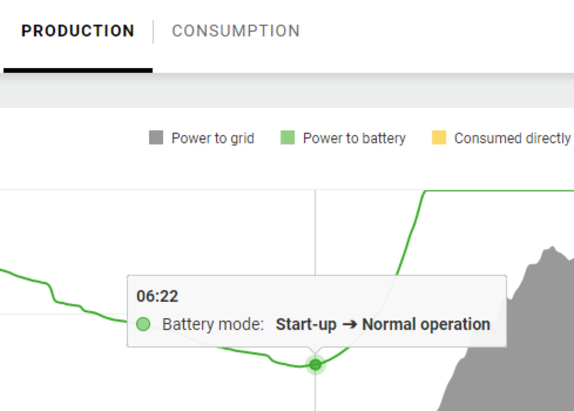
Battery state change from Start-up to Normal Operation.
The changes could be triggered as follows:
- A minimum state of charge is set using the register MinRsvPct, the corresponding state change is “Energy-saving mode”.
- Setting the registers InWRte, OutWRte, StorCtl_Mod the battery status could change to “Forced Recharge”.
String Combiner Model (403)
String Combiner Register
The Register tables can be found on the Fronius homepage or opened using the link:
http://www.fronius.com/QR-link/0006
String Combiner Register
The Register tables can be found on the Fronius homepage or opened using the link:
http://www.fronius.com/QR-link/0006
Meter Model
Meter Model Register
In a similar way to the inverter models, there are also two different SunSpec models in this case:
- the meter model with floating point display
(setting "float"; 211, 212 or 213) - the meter model with integers and scaling factors
(setting "int+SF"; 201, 202 or 203)
The register number of the two model types is different!
The Modbus device ID of the energy meter is 240.
The Register tables can be found on the Fronius homepage or opened using the link:
http://www.fronius.com/QR-link/0006
There are 4 different meter locations, which are described by the location number (see table). Depending on where the Smart Meter is located and whether the inverter is producing or consuming, the signs of the PowerReal values and the Energy values change. These are shown in the following table:
Meter_Location | 0 (grid) | 1 (load) | 3 (ext. generator) | 256-511 (subload) |
|---|---|---|---|---|
PowerReal_P_Sum (+ positive) | consuming from grid | producing power | generation | load is producing power |
PowerReal_P_Sum (- negative) | feeding in to grid | normal consumption | consumption | normal consumption |
energy plus (absolute counter) | import from grid = energy consumed | producing power* = energy produced | generation = energy produced | producing power* = energy produced |
energy minus (absolute counter) | export to grid = energy produced | consumption = energy consumed | consumption = energy consumed | consumption = energy consumed |
Meter Model Register
In a similar way to the inverter models, there are also two different SunSpec models in this case:
- the meter model with floating point display
(setting "float"; 211, 212 or 213) - the meter model with integers and scaling factors
(setting "int+SF"; 201, 202 or 203)
The register number of the two model types is different!
The Modbus device ID of the energy meter is 240.
The Register tables can be found on the Fronius homepage or opened using the link:
http://www.fronius.com/QR-link/0006
There are 4 different meter locations, which are described by the location number (see table). Depending on where the Smart Meter is located and whether the inverter is producing or consuming, the signs of the PowerReal values and the Energy values change. These are shown in the following table:
Meter_Location | 0 (grid) | 1 (load) | 3 (ext. generator) | 256-511 (subload) |
|---|---|---|---|---|
PowerReal_P_Sum (+ positive) | consuming from grid | producing power | generation | load is producing power |
PowerReal_P_Sum (- negative) | feeding in to grid | normal consumption | consumption | normal consumption |
energy plus (absolute counter) | import from grid = energy consumed | producing power* = energy produced | generation = energy produced | producing power* = energy produced |
energy minus (absolute counter) | export to grid = energy produced | consumption = energy consumed | consumption = energy consumed | consumption = energy consumed |
End Block
General
The addresses of these two registers are different depending on the device type (inverter, String Control, energy meter) and selected data type ("float" or "int+SF").
- Inverter:
- - Start address for setting "float": 40313
- - Start address for setting "int+SF": 40303
- Fronius String Control:
- - Start address: 40127
- Energy meter:
- - Start address for setting "float": 40195
- - Start address for setting "int+SF": 40176
General
The addresses of these two registers are different depending on the device type (inverter, String Control, energy meter) and selected data type ("float" or "int+SF").
- Inverter:
- - Start address for setting "float": 40313
- - Start address for setting "int+SF": 40303
- Fronius String Control:
- - Start address: 40127
- Energy meter:
- - Start address for setting "float": 40195
- - Start address for setting "int+SF": 40176
End Block
The Register tables can be found on the Fronius homepage or opened using the link:
http://www.fronius.com/QR-link/0006
String Combiner Event Flags
String Combiner
Event Flags
Name | Event Flags |
|
|---|---|---|
LOW_VOLTAGE | 0x00000001 |
|
LOW_POWER | 0x00000002 |
|
LOW_EFFICIENCY | 0x00000004 |
|
CURRENT | 0x00000008 |
|
VOLTAGE | 0x00000010 |
|
POWER | 0x00000020 |
|
PR | 0x00000040 |
|
DISCONNECTED | 0x00000080 |
|
FUSE_FAULT | 0x00000100 |
|
COMBINER_FUSE_FAULT | 0x00000200 |
|
COMBINER_CABINET_OPEN | 0x00000400 |
|
TEMP | 0x00000800 |
|
GROUNDFAULT | 0x00001000 |
|
REVERSED_POLARITY | 0x00002000 |
|
INCOMPATIBLE | 0x00004000 |
|
COMM_ERROR | 0x00008000 |
|
INTERNAL_ERROR | 0x00010000 |
|
THEFT | 0x00020000 |
|
ARC_DETECTED | 0x00040000 |
|
String Combiner
Event Flags
Name | Event Flags |
|
|---|---|---|
LOW_VOLTAGE | 0x00000001 |
|
LOW_POWER | 0x00000002 |
|
LOW_EFFICIENCY | 0x00000004 |
|
CURRENT | 0x00000008 |
|
VOLTAGE | 0x00000010 |
|
POWER | 0x00000020 |
|
PR | 0x00000040 |
|
DISCONNECTED | 0x00000080 |
|
FUSE_FAULT | 0x00000100 |
|
COMBINER_FUSE_FAULT | 0x00000200 |
|
COMBINER_CABINET_OPEN | 0x00000400 |
|
TEMP | 0x00000800 |
|
GROUNDFAULT | 0x00001000 |
|
REVERSED_POLARITY | 0x00002000 |
|
INCOMPATIBLE | 0x00004000 |
|
COMM_ERROR | 0x00008000 |
|
INTERNAL_ERROR | 0x00010000 |
|
THEFT | 0x00020000 |
|
ARC_DETECTED | 0x00040000 |
|