Safety rules
Explanation of Safety Instructions
DANGER!
Indicates an immediate danger.
Death or serious injury may result if appropriate precautions are not taken.
WARNING!
Indicates a possibly dangerous situation.
Death or serious injury may result if appropriate precautions are not taken.
CAUTION!
Indicates a situation where damage or injury could occur.
Minor injury or damage to property may result if appropriate precautions are not taken.
NOTE!
Indicates the possibility of flawed results and damage to the equipment.
General
- serious or fatal injury to the operator or a third party,
- and damage to the device and other material assets belonging to the operating company.
- be suitably qualified,
- have knowledge of and experience in dealing with electrical installations and
- have fully read and precisely followed these Operating Instructions.
The Operating Instructions must always be kept on hand wherever the device is being used. In addition to the Operating Instructions, all applicable local rules and regulations regarding accident prevention and environmental protection must also be followed.
All safety and danger notices on the device- must be kept in a legible state
- must not be damaged/marked
- must not be removed
- must not be covered, pasted, or painted over.
The terminals can reach high temperatures.
Only operate the device when all protection devices are fully functional. If the protection devices are not fully functional, there is a risk of- serious or fatal injury to the operator or a third party,
- and damage to the device and other material assets belonging to the operating company.
Any safety devices that are not functioning properly must be repaired by an authorized specialist before the device is switched on.
Never bypass or disable protection devices.
For the location of the safety and danger notices on the device, refer to the section headed “General” in the Operating Instructions for the device.
Any equipment malfunctions which might impair safety must be remedied immediately before the device is turned on.
Your personal safety is at stake!
Environmental conditions
Operation or storage of the device outside the stipulated area will be deemed as not in accordance with the intended purpose. The manufacturer accepts no liability for any damage resulting from improper use.
Qualified personnel
The information contained in these operating instructions is intended only for qualified personnel. An electric shock can be fatal. Do not carry out any actions other than those described in the documentation. This also applies to qualified personnel.
All cables must be secured, undamaged, insulated, and adequately dimensioned. Loose connections, damaged or under-dimensioned cables must be repaired immediately by an authorized specialist company.
Maintenance and repair work must only be carried out by an authorized specialist company.
It is impossible to guarantee that third-party parts are designed and manufactured to meet the demands made on them, or that they satisfy safety requirements. Only use original spare parts.
Do not carry out any alterations, installations, or modifications to the device without first obtaining the manufacturer's permission.
Replace any damaged components or have them replaced immediately.
Data Regarding Noise Emission Values
The inverter generates a maximum sound power level of < 65 dB(A) (ref. 1 pW) when operating under full load in accordance with IEC 62109-1:2010.
The device is cooled as quietly as possible with the aid of an electronic temperature control system, and depends on the amount of converted power, the ambient temperature, the level of soiling of the device, etc.
It is not possible to provide a workplace-related emission value for this device, because the actual sound pressure level is heavily influenced by the installation situation, the power quality, the surrounding walls and the properties of the room in general.
EMC measures
In certain cases, even though a device complies with the standard limit values for emissions, it may affect the application area for which it was designed (e.g., when there is equipment that is susceptible to interference at the same location or if the site where the device is installed is close to either radio or television receivers). If this is the case, the operator is obliged to take action to rectify the situation.
Safety symbols
Devices marked with the CSA test mark satisfy the requirements of the relevant standards for Canada and the USA.
Disposal
Dispose of in accordance with the applicable national and local regulations.
Data backup
- backing up any changes made to the factory settings
- saving and storing personal settings
Copyright
Copyright of these operating instructions remains with the manufacturer.
Text and illustrations were accurate at the time of printing, subject to change.
We are grateful for suggestions for improvement and information on any discrepancies in the operating instructions.
General
Device concept

Device construction:
| (1) | Housing cover |
| (2) | Inverter |
| (3) | Wall bracket |
| (4) | Connection area incl. DC main switch |
| (5) | Data communication area |
| (6) | Data communication cover |
The inverter transforms the direct current generated by the solar modules into alternating AC current. This alternating current is fed into your home system or into the public grid and synchronized with the voltage that is used there.
The inverter has been designed exclusively for use in grid-connected photovoltaic systems. It cannot generate electric power independently of the grid.
The design and function of the inverter provide a maximum level of safety during both installation and operation.
The inverter automatically monitors the public grid. Whenever conditions in the electric grid are inconsistent with standard conditions (for example, grid switch-off, interruption), the inverter will immediately stop operating and interrupt the supply of power into the grid.
Grid monitoring is carried out using voltage monitoring, frequency monitoring and monitoring islanding conditions.
The inverter is fully automatic. Starting at sunrise, as soon as the solar modules generate enough energy, the inverter starts monitoring grid voltage and frequency. As soon as there is a sufficient level of irradiance, the solar inverter starts feeding energy into the grid.
The inverter ensures that the maximum possible power output is drawn from the solar modules at all times.
When there is no longer sufficient energy available to feed power into the grid, the inverter shuts down the grid connection completely and stops operating. All settings and recorded data are saved.
If the inverter temperature exceeds a certain value, the inverter automatically derates power output for self-protection.
The cause for a too high inverter temperature can be found in a high ambient temperature or an inadequate heat transfer away (eg for installation in control cabinets without proper heat dissipation).
Device concept
Device construction:
| (1) | Housing cover |
| (2) | Inverter |
| (3) | Wall bracket |
| (4) | Connection area incl. DC main switch |
| (5) | Data communication area |
| (6) | Data communication cover |
The inverter transforms the direct current generated by the solar modules into alternating AC current. This alternating current is fed into your home system or into the public grid and synchronized with the voltage that is used there.
The inverter has been designed exclusively for use in grid-connected photovoltaic systems. It cannot generate electric power independently of the grid.
The design and function of the inverter provide a maximum level of safety during both installation and operation.
The inverter automatically monitors the public grid. Whenever conditions in the electric grid are inconsistent with standard conditions (for example, grid switch-off, interruption), the inverter will immediately stop operating and interrupt the supply of power into the grid.
Grid monitoring is carried out using voltage monitoring, frequency monitoring and monitoring islanding conditions.
The inverter is fully automatic. Starting at sunrise, as soon as the solar modules generate enough energy, the inverter starts monitoring grid voltage and frequency. As soon as there is a sufficient level of irradiance, the solar inverter starts feeding energy into the grid.
The inverter ensures that the maximum possible power output is drawn from the solar modules at all times.
When there is no longer sufficient energy available to feed power into the grid, the inverter shuts down the grid connection completely and stops operating. All settings and recorded data are saved.
If the inverter temperature exceeds a certain value, the inverter automatically derates power output for self-protection.
The cause for a too high inverter temperature can be found in a high ambient temperature or an inadequate heat transfer away (eg for installation in control cabinets without proper heat dissipation).
Intended Use
The inverter is designed exclusively to be connected and used with nongrounded solar modules. The solar modules cannot be grounded at either the positive or negative pole.
The solar inverter is designed exclusively to convert direct current from solar modules into alternating current and feed this power into the public grid.The following are deemed not to be in conformity with its intended purpose:
- utilization for any other purpose, or in any other manner
- alterations to the inverter that are not expressly recommended by Fronius
- installation of components that are not expressly recommended or sold by Fronius.
The manufacturer is not responsible for any damage resulting from improper use.
All warranty claims are considered void in such cases.
- carefully reading and obeying all the instructions and safety and danger notices in the operating instructions
- carrying out all the specified inspection and servicing work
- installation as per operating instructions.
When configuring the photovoltaic system, make sure that all photovoltaic system components are operating completely within their permitted operating range.
All measures recommended by the solar module manufacturer for maintaining solar module properties must be followed.
Utility company regulations regarding grid power feed must be followed.
Information on ‘Field-adjustable trip points’ and ‘Advanced Grid Features’
The inverter is equipped with ‘Field adjustable trip points’ and ‘Advanced Grid Features’. For further information, please contact ‘Fronius Technical Support’ at the following email address: pv-support-usa@fronius.com.
FCC / RSS Compliance
FCC
This device corresponds to the limit values for a digital device of class B in accordance with Part 15 of the FCC regulations. The limit values should provide adequate protection against harmful interference in homes. This device creates and uses high frequency energy and can interfere with radio communications when not used in accordance with the instructions. However, there is no guarantee against interference occurring in a particular installation.
If this device interferes with radio or television reception when turning the device on and off, it is recommended that the user solve this with one or more of the following measures:
- adjust or reposition the receiving antenna
- increase the distance between the device and the receiver
- connect the device to another circuit, which does not include the receiver
- for further support, please contact the retailer or an experienced radio/TV technician.
Industry Canada RSS
The device corresponds to the license-free Industry Canada RSS standards. Operation is subject to the following conditions:
(1) The device may not cause harmful interference
(2) The device must accept any interference received, including interference that may cause undesired operation.
Insulation Monitoring
The inverter is fitted with the following safety function as required by UL 1741 and the National Electrical Code:
Insulation monitoring
In photovoltaic systems with ungrounded solar modules, the inverter checks the resistance between the photovoltaic system's positive or negative pole and the ground potential. In the case of a short circuit between the DC+ or DC- cable and the ground (e.g., due to poorly insulated DC cables or faulty solar modules) the inverter disconnects from the grid.
Arc detection/interruption
The inverter is equipped with integrated arc detection/interruption, which detects and extinguishes serial arcs.
For example, a serial arc can occur after the following errors or situations:
- Poorly-connected plug connections on the solar module
- Poor or defective cable connections on the solar module side, which enable a connection against the earth potential
- Defective solar modules due to problems in the junction box or production errors, such as high resistance solder connections in individual solar cells
- Cables incorrectly connected to an inverter’s input terminals
If a serial arc is detected, the power is switched off and the grid power feed operation is interrupted. A state code is shown on the display. The state code on the display must be manually reset before the grid power feed operation can be resumed.
The power shutdown also extinguishes the serial arc.
NOTE!
This product is equipped with a communication interface in line with the "Communication Signal for Rapid Shutdown - SunSpec Interoperability Specification”.
Power optimizers and other MLPE features in the photovoltaic system can impair the correct functioning of the arc detection/interruption. When using these kinds of components, the system installer is responsible for ensuring the correct functioning of the arc detection/interruption. Contact your Fronius Technical Support for more information.
Warning notices on the device
There are warning notices and safety symbols on the inside and outside of the inverter. These warnings and safety symbols must not be removed or painted over because they are required by the standard. They warn against incorrect operation, as this may result in serious injury and property damage.
 |
| Safety symbols: | |
|  | Danger of serious injury and property damage due to incorrect operation | |
|  | Do not use the functions described here until you have fully read and understood the following documents:
| |
|  | Dangerous electrical voltage | |
|  | Wait for the capacitors to discharge. | |
Text of the warning notices:
WARNING!
Risk of electric shock
Non-insulated inverter
Do not remove the cover. The device does not contain any user-serviceable parts. Maintenance work must be carried out by a trained service technician.
Both AC and DC voltage sources terminate inside this device. Each circuit must be turned off before carrying out maintenance work.
If the solar module is exposed to light, it will supply a DC voltage to the device.
Risk of electric shock due to energy stored in capacitors. Do not remove the cover until all power supply sources have been switched off for at least 5 minutes.
Ungrounded system: The DC cables in this PV system are not grounded and can be live.
String Fuses
You can give solar modules extra protection by using string fuses inside the Fronius Primo 10-15 kW.
Crucial for the fuse protection of the solar modules is the maximum short circuit current Isc of the relevant solar module.
National regulations regarding fuse protection must be observed. The electrician performing the installation is responsible for choosing the right string fuses.
NOTE!
To prevent a risk of fire, faulty fuses must only be replaced by new equivalent fuses.
- 4x 15 A string fuses at DC+ input (MPPT1) and 4x metal bolts at DC- input
- 8x metal bolts

Criteria for the Proper Selection of String Fuses
- IN > 1.5 x ISC
- VN >/= maximum open circuit voltage of pv generator
- Fuse dimensions: Diameter 10 x 38 mm
| IN | Nominal current of the fuse |
| ISC | Short circuit current for standard test conditions (STC) according to solar module data sheet |
| VN | Nominal voltage of the fuse |
NOTE!
The nominal current value of the fuse must not exceed the maximum fuse protection value specified in the solar module manufacturer's data sheet.
If a maximum fuse protection value is not specified, please request it from the solar module manufacturer.
Data Communication and Fronius Solar Net
Fronius Solar Net and data interface
Fronius developed Solar Net to make these system add-ons flexible and capable of being used in a wide variety of different applications. Fronius Solar Net is a data network that enables several inverters to be linked to the system add-ons. | |
Fronius Solar Net is a bus system with ring topology. Just one suitable cable is enough for communication between one or more inverters connected to Fronius Solar Net and a system add-on. | |
In order to clearly define each inverter in Fronius Solar Net, each inverter must also be assigned an individual number. | |
Different system add-ons are automatically recognized by Fronius Solar Net. | |
In order to distinguish between several identical system add-ons, each one must be assigned a unique number. | |
More detailed information on the individual system add-ons can be found in the relevant operating instructions or on the internet at http://www.fronius.com | |
More detailed information on cabling Fronius DATCOM components can be found at: | |
 | → http://www.fronius.com/QR-link/4204101938 |
Fronius Solar Net and data interface
Fronius developed Solar Net to make these system add-ons flexible and capable of being used in a wide variety of different applications. Fronius Solar Net is a data network that enables several inverters to be linked to the system add-ons. | |
Fronius Solar Net is a bus system with ring topology. Just one suitable cable is enough for communication between one or more inverters connected to Fronius Solar Net and a system add-on. | |
In order to clearly define each inverter in Fronius Solar Net, each inverter must also be assigned an individual number. | |
Different system add-ons are automatically recognized by Fronius Solar Net. | |
In order to distinguish between several identical system add-ons, each one must be assigned a unique number. | |
More detailed information on the individual system add-ons can be found in the relevant operating instructions or on the internet at http://www.fronius.com | |
More detailed information on cabling Fronius DATCOM components can be found at: | |
| → http://www.fronius.com/QR-link/4204101938 |
Installing Option Cards in Inverters
Information on installing option cards (e.g.: Datamanager) in the inverters and for connecting data communication cables can be found in the installation instructions.
System monitoring
General
The inverter is equipped with the Wi-Fi enabled system monitoring of the Fronius Data Manager 2.0.
The monitoring system includes the following functions:
- own website with display of actual data and a wide variety of settings
- Connection-possibility to Fronius Solar.web via WiFi or LAN
- automatic sending of service messages via SMS or e-mail in case of errors
- Possibility to control the inverter by setting of power limits, minimum or maximum operational times or target operational times
- Controlling the inverter via Modbus (TCP / RTU)
- Allocation of control priorities
- Controlling the inverter by connected meters (Fronius Smart Meter)
- Controlling the inverter via a ripple control signal receiver (eg reactive power setting or power setting)
- dynamic power reduction considering the self consumption
Further information about the Fronius Data Manager 2.0 can be found online in the Fronius Data Manager 2.0 operating instructions.
Starting for the first time
- the Fronius Datamanager 2.0 plug-in card must be installed in the inverter,
or - there must be a Fronius Datamanager Box 2.0 in the Fronius Solar Net ring.
IMPORTANT! "Obtain an IP address automatically (DHCP)" must be activated for the end device in question (e.g., laptop, tablet, etc.) to establish a connection to the Fronius Datamanager 2.0.
NOTE!
If the photovoltaic system only has one inverter, the following work steps 1 and 2 can be skipped.
Start the process with work step 3 in this case.
1Connect the inverters with Fronius Datamanager 2.0 or Fronius Datamanager Box 2.0 in Fronius Solar Net
2When networking several inverters in Fronius SolarNet:Set the Fronius Solar Net primary/secondary switch on the Fronius Datamanager 2.0 plug-in card correctly
- One inverter with Fronius Datamanager 2.0 = primary
- All other inverters with Fronius Datamanager 2.0 = secondary (the LEDs on the Fronius Datamanager 2.0 plug-in cards are off)
3Switch the inverters to service mode
- Activate the WLAN Access Point via the inverter's setup menu

The inverter establishes the WLAN Access Point. The WLAN Access Point stays open for one hour. The IP switch on the Fronius Datamanager 2.0 can remain in switch position B by activating the WLAN Access Point.
| Installation via Web Browser |
| 4Connect the end device to the WLAN Access PointSSID = FRONIUS_240.xxxxx (5-8 digits)
5Enter in the browser: http://datamanager or 192.168.250.181 (IP address for WLAN connection) or 169.254.0.180 (IP address for LAN connection) |
|
|
The start page of the Setup wizard appears.
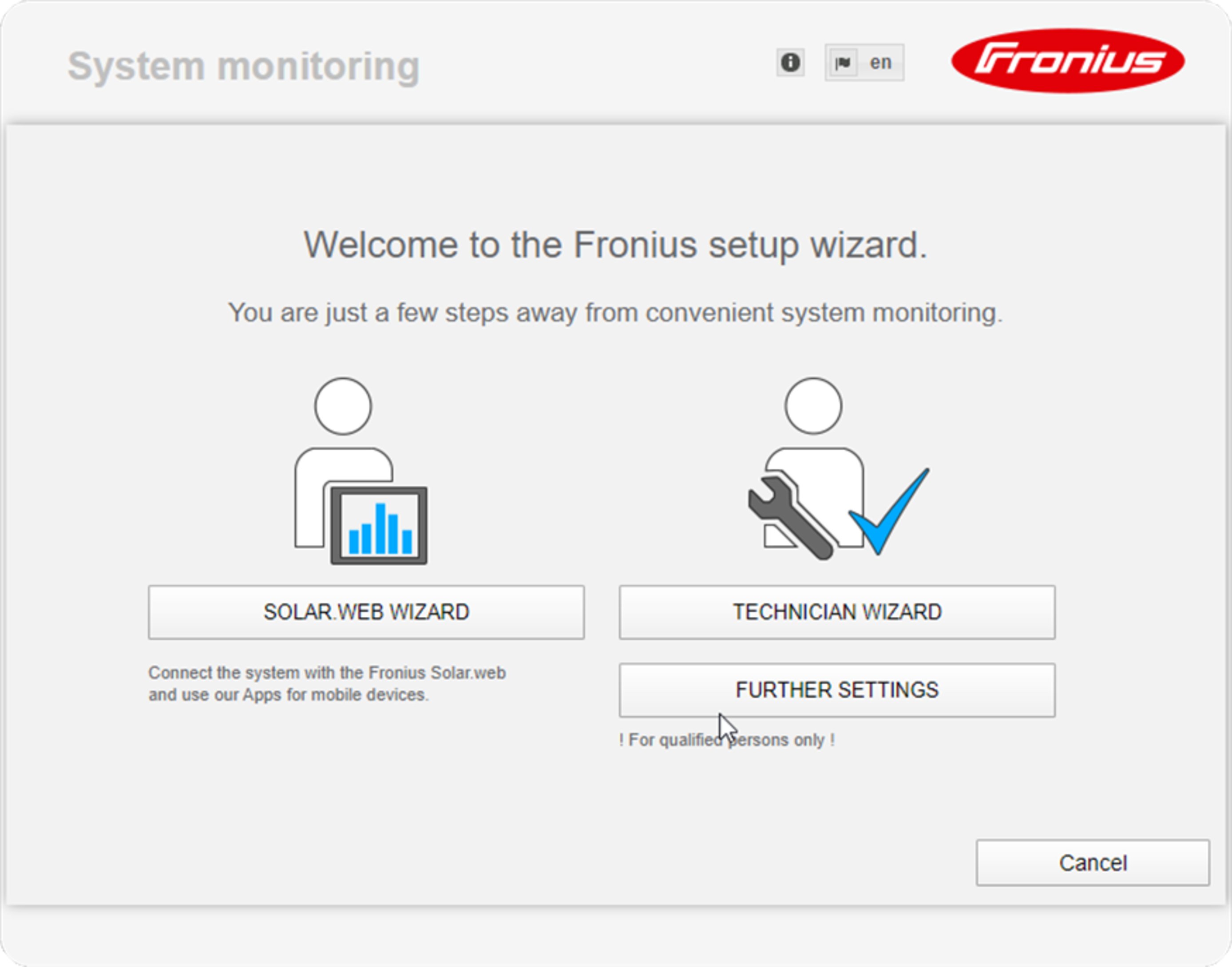
The Technician Wizard is designed for the installer and includes standard-specific settings. Running the Technician Wizard is optional.
If the Technician Wizard is run, it is essential to note down the assigned service password. This service password is required to configure the UC Editor menu item.
If the Technician Wizard is not run, no specifications for power reduction are set.
The Fronius Solar Web Wizard must be run.
6Run the Fronius Solar Web Wizard and follow the instructions
The Fronius Solar.web start page appears.
or
The Fronius Datamanager 2.0 website opens.
7If necessary, run the Technician Wizard and follow the instructions
More Detailed Information on Fronius Datamanager 2.0
More detailed information on Fronius Datamanager 2.0 and other start-up options can be found at: | |
 | → http://www.fronius.com/QR-link/4204260191EA |
Keys and symbols
Operating elements and displays

Item | Description |
|---|---|
(1) | Display |
Control and status LEDs | |
(2) | General status LED (red)
|
(3) | Status LED (orange)
|
(4) | Operating LED (green)
|
| |
(5) | "Left/Up" key |
(6) | "Down/Right" key |
(7) | "Menu/Esc" key |
(8) | "Enter" key |
The keys are capacitive by design and wetting them with water may impair their function. For optimal function, wipe the keys with a dry cloth if necessary.
Operating elements and displays
Item | Description |
|---|---|
(1) | Display |
Control and status LEDs | |
(2) | General status LED (red)
|
(3) | Status LED (orange)
|
(4) | Operating LED (green)
|
| |
(5) | "Left/Up" key |
(6) | "Down/Right" key |
(7) | "Menu/Esc" key |
(8) | "Enter" key |
The keys are capacitive by design and wetting them with water may impair their function. For optimal function, wipe the keys with a dry cloth if necessary.
Display
Power for the display comes from the AC grid voltage. The display can be available all day long depending on the setting in the Setup menu.
IMPORTANT! The inverter display is not a calibrated measuring instrument.
Slight deviation from the utility company meter is intrinsic to the system. A calibrated meter is required to make calculations for the utility company.

Display area, display mode

Display area, setup mode
| (*) | Scroll bars |
| (**) | The Energy Manager symbol is displayed, if the Energy Manager function has been activated |
| (***) | WR no. = InverterDATCOM number, Store icon – appears briefly when set values are stored, USB connection – appears if a USB flash drive has been inserted |
Menu level
Activate the display illumination
1Press any key.
The display illumination is activated.
The SETUP menu, under the ‘Display settings - illumination’ entry, offers a choice between a permanently lit or permanently dark display.
The display illumination is activated.
The SETUP menu, under the ‘Display settings - illumination’ entry, offers a choice between a permanently lit or permanently dark display.
Automatic Deactivation of Display Illumination / Switching to the "NOW" Display Mode
If no key is pressed for 2 minutes, the display illumination turns off automatically and the inverter switches to the ‘NOW’ display mode (if the display illumination is set to AUTO).
The inverter can automatically be switched to the ‘NOW’ display mode from any menu level, unless the inverter was manually switched to standby mode.
The current power feed-in is displayed after automatically switching to the ’NOW’ menu item.
Accessing the menu level
 | 1Press the "Menu"  key key |
 | The display switches to the menu level. |
2Use the "left" or "right" key  to select the desired menu item to select the desired menu item | |
3Access the desired menu item by pressing the "Enter"  key key |
Menu items NOW, LOG, and GRAPH
NOW
LOG
GRAPH
| NOW |
 | LOG |
 | GRAPH Press the "Back" key to close the display |
NOW
LOG
GRAPH
| NOW |
| LOG |
| GRAPH Press the "Back" key to close the display |
Values Displayed in the Menu Items NOW and LOG
Data displayed in menu item NOW:
AC Output Power (W) |
AC Reactive Power (VAr) |
AC Voltage (V) |
AC Output Current (A) |
AC Frequency (Hz) |
PV Array Voltage (V) |
PV Array Current (A) |
Time / Date |
Data displayed in menu item LOG:
(for the current day, the current calendar year, and since using the inverter for the first time)
AC Energy Yield (kWh / MWh) Due to the variety of different monitoring systems, there can be deviations between the readings of other metering instruments and the readings from the inverter. For determining the energy supplied to the grid, only the readings of the calibrated meter supplied by the electric utility company are relevant. |
AC Maximum output power (W) |
Earnings As was the case for the output energy, readings may differ from those of other instruments. "The Setup Menu" section describes how to set the currency and rate for the energy supplied. |
CO2 savings (g / kg) The value for CO2 savings depends on the power station facilities and corresponds to the CO2 emissions that would be released when generating the same amount of energy. The factory setting is 0.53 kg / kWh (source: DGS – Deutsche Gesellschaft für Sonnenenergie e.V. (German Society for Solar Energy). |
AC Max. Voltage L-N (V) |
PV Array Max. Voltage (V) |
Operating Hours IMPORTANT! The time must be set correctly for day and year values to be displayed properly. |
The SETUP menu item
Presetting
After completing the entire start-up process (for example, using the Installation Wizard), the inverter is preconfigured depending on the country setup.
The SETUP menu lets you easily customize the inverter’s preset parameters to your needs.
Presetting
After completing the entire start-up process (for example, using the Installation Wizard), the inverter is preconfigured depending on the country setup.
The SETUP menu lets you easily customize the inverter’s preset parameters to your needs.
SETUP
 |
| SETUP |
NOTE!
Because of software updates, certain functions may be available for your device but not described in these Operating Instructions or vice versa.
In addition, individual figures may also differ slightly from the operating elements of your device. These operating elements function in exactly the same way, however.
Navigation in the SETUP Menu
Accessing the SETUP menu | |
"SETUP" mode selected at the menu level | 1In the menu level, use the "left" or "right" keys to select the "SETUP" menu item |
2Press the "Enter" key | |
 "Standby" entry | The first entry in the SETUP menu is displayed: |
Scrolling between entries | |
 Example: "WiFi Access Point" menu item | 3Use the "up" or "down" keys  to scroll between the available entries to scroll between the available entries |
Exiting an entry | |
| 4To exit an entry, press the "Back" keyThe menu level is displayed |
- the inverter switches from any item within the menu level to the "NOW" menu item (exception: Setup menu item "Standby").
- The display illumination turns off.
- The current power of feeding in is displayed.
General Menu Item Settings
1Access the desired menu
2Use the ‘Up’ and ‘Down’ keys to select the desired entry
3Press the "Enter" key
The available settings are displayed: |
| The first digit of a value to be set flashes: |
4Use the ‘Up’ and ‘Down’ keys to select the desired setting 5Press the ‘Enter’ key to save and apply the selection. Press the ‘Esc’ key to exit without saving. | 4Use the "Up" and "Down" keys to select a value for the first digit 5Press the "Enter" key The second digit of the value flashes. 6Repeat steps 4 and 5 until... the entire value flashes. | |
| 7Press the "Enter" key 8Repeat steps 4 - 6 for units or other values to be set until the unit or value flashes. 9Press the ‘Enter’ key to save and apply the changes. Press the ‘Esc’ key to exit without saving. | |
The currently selected entry is displayed. |
| The currently selected entry is displayed. |
Application Example: Setting the Feed-In Tariff
 | 1Select the ‘Energy yield’ setup menu entry |
2Press the ‘Enter’ key | |
| |
 | The overview of adjustable values is displayed. |
3Use the ‘up’ or ‘down’ keys to select the ‘Feed-in tariff’ | |
4Press the ‘Enter’ key | |
 | The feed-in tariff is displayed |
5Use the ‘plus’ or ‘minus’ keys  to select a value for the tens digit to select a value for the tens digit | |
6Press the ‘Enter’ key | |
 | The units position flashes. |
7Repeat steps 5 and 6 for the units position and the 3 decimal places until ... | |
 | The set feed-in tariff flashes. |
8Press the ‘Enter’ key | |
| The feed-in tariff is applied and the overview of adjustable values is displayed. |
9Press the ‘Esc’ | |
| The ‘Energy yield’ setup menu entry is displayed. |
|
The Setup menu item
Standby
Manual activation/deactivation of the standby mode
- No energy is fed into the grid.
- The Startup LED lights up orange.
- The display switches between STANDBY/ENTER
- In standby mode, no other menu item can be accessed or set in the menu level.
- The automatic switching to the ‘NOW’ menu item after 2 minutes if no key is pressed is not activated.
- The standby mode can only be deactivated manually by pressing the ‘Enter’ key.
- The grid power feed operation can be resumed at any time by pressing the ‘Enter’ key, if no error (state code) is displayed
Setting the standby mode (manual shutoff for feeding energy into the grid):
1Select the ‘Standby’ entry
2Press the ‘Enter’ function key
The display alternates between ‘STANDBY’ and ‘ENTER.’
The Standby mode is now activated.
The Startup LED lights up orange.
Restoring the grid power feed operation:
In Standby mode, the display alternates between ‘STANDBY’ and ‘ENTER’.
In Standby mode, the display alternates between ‘STANDBY’ and ‘ENTER’.
1Press the ‘Enter’ function key to restore the grid power feed operation
to restore the grid power feed operationThe ‘Standby’ entry is displayed.
The inverter also switches to the Startup phase.
After the grid power feed operation is restored, the Operation Status LED lights up green.
WLAN Access Point
To activate/deactivate the WLAN Access Point. For example, this is required to set up or adjust the system monitoring using the Datamanager web interface. If no Datamanager is detected by the inverter, [not available] is displayed
Setting range | WLAN Access Point |
| Activate WLAN AP? To activate the WLAN Access Point |
| WLAN Access Point The SS-ID (SS) and the password (PW) are displayed. |
| Deactiv. WLAN AP? To deactivate the WLAN Access Point |
| WLAN Access Point Is displayed if no system monitoring is available on the inverter. |
DATCOM
Check the data communication, entry of the inverter number, protocol settings
Setting range | Status/inverter number/protocol type |
Status | |
Inverter Number | |
Setting range | 00 - 99 (00 = inverter address 100) |
Factory setting | 01 |
IMPORTANT! Each inverter must be assigned its own address when using multiple inverters in a data communications system. | |
Protocol Type | |
Setting range | Fronius Solar Net / Interface * |
Factory setting | Fronius Solar Net |
* The interface protocol type only functions without a Fronius Datamanager card. Existing Fronius Datamanager cards must be removed from the inverter. | |
USB
Value settings when using a USB stick
Setting range | Safely remove hardware / software update / logging interval |
IMPORTANT! The time must be set correctly in order for the logging function to work properly.
Safely remove hardware
|
Software update |
Procedure: 1Download the "froxxxxx.upd" update file (e.g., at http://www.fronius-usa.com; xxxxx stands for the respective version number) |
IMPORTANT! To ensure problem-free updates of inverter software, the USB stick should have no hidden partitions and no encryption (see section "Suitable USB Sticks). |
2Save the update file to the highest data level of the USB stick 3Open the data communication area 4Insert the USB stick with the update file into the USB socket in the data communication area 5In the Setup menu, select the menu item "USB" and then "Update Software" 6Press the "Enter" key 7Wait until a comparison of the current software version on the inverter and the new software version is displayed:
8Press the "Enter" key after every page |
The inverter begins copying the data. |
After the copying is complete the inverter updates the required electronic assemblies one after the other. |
The inverter updates the display in the last step. |
When the software update is complete, the inverter switches to the startup phase and then to grid power feed operation. The USB stick can be removed.. |
Individual settings in the Setup menu are retained when the inverter software is updated. |
Logging Interval |
Unit | Minutes |
Setting range | 30 Min. / 20 Min. / 15 Min. / 10 Min. / 5 Min. / No Log |
Factory setting | 30 Min. |
|
|
30 Min. | The logging interval is 30 minutes; new logging data are saved to the USB stick every 30 minutes. |
20 Min. |  |
15 Min. | |
10 Min. | |
5 Min. | The logging interval is 5 minutes; new logging data are saved to the USB stick every 5 minutes. |
No Log | No data are saved |
IMPORTANT! The time must be set correctly in order for the logging function to work properly. | |
Relay (Floating Switch Contact)
A floating switch contact (relay) on the inverter can be used to display status codes, the inverter status (e.g. the grid power feed operation) or the Energy Manager functions.
Setting range | Relay Mode / Relay Test / Switch-on Point* / Switch-off Point* |
* is only shown if the “E-Manager” function has been activated under “Relay Mode.”
Relay Mode
| |
Setting range | ALL / Permanent / GAF / OFF / ON / E-manager |
Factory setting | ALL |
Alarm function: | ||
ALL / Permanent: | Switches the floating switch contact for continual and temporary service codes (e.g. brief interruption of grid power feed operation, a service code occurs a certain number of times per day – can be set in the “BASIC” menu) | |
GAF | As soon as “GAF” mode is selected, the relay will be switched on. As soon as the power module reports an error and switches from regular grid power feed operation to an error state, the relay is opened. This way, the relay can be used for fail safe functions. Application example | |
Active output: | ||
ON: | The floating NO switch contact is constantly switched on while the inverter is operating (as long as the display lights up or displays). | |
OFF: | The floating NO switch contact is switched off. | |
Energy Manager: | ||
E-Manager: | You can find additional information on the “Energy Manager” function in the following “Energy Manager” section. | |
Relay test | ||
Switch-on point (only if the “Energy Manager” function is activated) | ||
Factory setting | 1000 W |
Setting range | set switch-off point up to the inverter’s nominal output (W or kW) |
Switch-off point (only if the “Energy Manager” function is activated) | |
Factory setting | 500 |
Setting range | 0 up to the inverter’s set switch-on point (W or kW) |
Time/Date
Setting the time, date, display format, and automatic adjustment for daylight saving time
Setting range | Set time / Set date / Time display format / Date display format / Daylight saving time |
Set time | |
Set date | |
Time display format | |
Setting range | 12hrs/24hrs |
Factory setting | depends on the country setup |
Date display format | |
Setting range | mm/dd/yyyy or dd.mm.yy |
Factory setting | depends on the country setup |
Daylight saving time | |
IMPORTANT! Only use the automatic daylight savings changeover function when there are no LAN or WLAN-compatible system components in a Fronius Solar Net ring (e.g. Fronius Datalogger Web, Fronius Datamanager or Fronius Hybridmanager). | |
Setting range | on/off |
Factory setting | on |
IMPORTANT! The time and date must be set correctly for day and year values to be displayed properly. | |
Display Settings
Setting range | Language / Night Mode / Contrast / Illumination |
Language | |
Setting range | English, German, French, Spanish, Italian, Dutch, Czech, Slovakian, Hungarian, Polish, Turkish, Portuguese, Romanian |
Night mode | |
Setting range | AUTO / ON / OFF |
Factory setting | OFF |
AUTO: | The Fronius DATCOM operation is maintained as long as a Fronius Datamanager is connected to an active, uninterrupted Fronius Solar Net. | |
ON: | The Fronius DATCOM operation is always maintained. The inverter provides an uninterrupted 12 V DC voltage to supply Fronius Solar Net with power. The display is always active. IMPORTANT! When the Fronius DATCOM night mode is ON or on AUTO with connected Fronius Solar Net components, the power consumption of the inverter at night increases to around 7 W. | |
OFF: | No Fronius DATCOM operation at night, the inverter therefore does not require any power to supply electricity to the Fronius Solar Net at night. | |
Contrast | ||
Setting range | 0 - 10 |
Factory setting | 5 |
Since contrast depends on temperature, it may be necessary to adjust the ‘Contrast’ menu item when environmental conditions change. | |
Illumination | |
The ‘Illumination’ menu item only applies to the inverter display background illumination. | |
Setting range | AUTO / ON / OFF |
Factory setting | AUTO |
AUTO: | The inverter display illumination is activated by pressing any key. If no key is pressed for 2 minutes, the display backlight goes out. | |
ON: | The inverter display illumination is permanently on when the inverter is active. | |
OFF: | The inverter display illumination is permanently off. |
Energy yield
- Meter deviation/calibration
- Currency
- Feed-in tariff
- CO2 factor
Setting range | Currency / Feed-in tariff |
Meter deviation/calibration | |
Currency | |
Setting range | 3-digit, A-Z |
Feed-in tariff | |
Setting range | 2-digit, 3 decimal places |
Factory setting | (depends on the country setup) |
CO2 factor | |
Fan
for checking the fan functionality
Setting range | Test fan #1 / Test fan #2 |
- Use the "Up" and "Down" keys to select Test fan #1
- Press the "Enter" key to start testing of the fans
- The fans run until the menu is exited by pressing the "Esc" key
Arc Detection
for checking arc detection/interruption
Setting range | ArcDetector Status/Start Self-test |
Arc.det. Status | |
Start Self-test Test procedure: 1Select "Arc Detection" in the Setup menu 2Press the "Enter" key 3Use the up and down keys to select "Start Self-test" 4Press the "Enter" key The self-test starts. The arc detection/interruption function simulates an arc and sends the corresponding signal to the inverter. The message "Self-test completed and Start AFCI" is shown on the display. 5Confirm the indication by pressing the "Enter" key | |
The INFO menu item
INFO
 | INFO |
INFO
| INFO |
Measured values
LT status
Grid status
Measured values | Display range: | PV Iso. / Ext. Lim. / U PV1 / U PV2 / GVDPR / Fan #1 |
| PV Iso. | |
| Ext. Lim. | |
| U PV1 | |
| U PV 2 | |
| GVDPR | |
| Fan #1 | |
LT Status | The status indicator of the last error that occurred in the inverter can be shown. IMPORTANT! Status codes 306 (Power low) and 307 (DC low) appear naturally every morning and evening due to low solar irradiance. These status codes are not the result of a fault.
| |
Grid status | The last 5 grid errors that occurred can be displayed:
| |
Device Information
Used to display settings relevant to a power supply company. The displayed values depend on the respective country setup or device-specific inverter settings.
Display range | General/Country Setup/MPP Tracker/AC Monitoring/AC Voltage Limits/AC Frequency Limits/Q-Mode/AC Power Limits/AC Voltage Derating / Fault Ride Through |
General: | Device type |
Country Setup: | Setup |
Version | |
Group | |
MPP Tracker: | Tracker 1 (status, voltage) |
Tracker 2 (status, voltage) | |
AC Monitoring: | GMTi |
GMTr | |
ULL | |
LLTrip | |
AC Voltage Limits: | UILmax |
UILmin | |
UOLmax | |
UOLmin | |
AC Frequency Limits: | FILmax |
FILmin | |
FOLmax | |
FOLmin | |
Q-Mode: | Currently set power factor (cos phi) |
AC Power Limits: | Max. P AC |
AC Voltage Derating: | Status |
GVDPRe | |
GVDPRv | |
Message | |
Fault Ride Through: | Status – default setting: OFF DB min – default setting: 90% DB max – default setting: 120% k-Fac. default setting: 0 |
Version
Display of version number and serial number of the PC boards installed in the inverter (e.g., for service purposes)
Display range | Display/Display Software/Integrity Checksum/Memory Card/Memory Card #1/Power Stage/Power Stage Software/EMI Filter/Power Stage #3/Power Stage #4 |
Switching the key lock on and off
General
The inverter comes equipped with a ‘Key lock’ function.
When the ‘Keylock’ function is active, the Setup menu cannot be accessed, e.g., to protect against setup data being changed by accident.
You must enter code 12321 to activate / deactivate the ‘Key lock’ function.
General
The inverter comes equipped with a ‘Key lock’ function.
When the ‘Keylock’ function is active, the Setup menu cannot be accessed, e.g., to protect against setup data being changed by accident.
You must enter code 12321 to activate / deactivate the ‘Key lock’ function.
Switching the Key Lock On and Off
1Press the ‘Menu’ key | |
| The menu level is displayed. 2Press the unassigned ‘Menu/Esc’ key 5 times  |
 | In the ‘CODE’ menu, the ‘Access Code’ is displayed and the first digit flashes. |
3Enter code 12321: Use the ‘plus’ or ‘minus’ keys to select the first digit of the code | |
4Press the ‘Enter’ key |
 | The second digit flashes. |
5Repeat steps 3 and 4 for the second, third, fourth, and fifth digit in the code until... the set code flashes. 6Press the ‘Enter’ key |
 | In the ‘LOCK’ menu, the ‘Key lock‘ function is displayed. |
7Use the ‘plus’ or ‘minus’ keys to switch the key lock on or off:ON = the key lock function is activated (the SETUP menu item cannot be accessed) OFF = the key lock function is deactivated (the SETUP menu item can be accessed) | |
8Press the ‘Enter’ key |
USB Stick as a Data Logger and for Updating Inverter Software
USB Stick as a Data Logger
A USB stick connected to the USB A socket can act as a data logger for an inverter.
Logging data saved to the USB stick can at any time- be imported into the Fronius Solar.access software via the included FLD file
- be viewed directly in third-party applications (e.g., Microsoft® Excel) via the included CSV file.
Older versions (up to Excel 2007) have a row limit of 65536.
Further information on "Data on a USB stick", "Data volume and storage capacity" as well as "Buffer memory" can be found at: | |
 | ® http://www.fronius.com/QR-link/4204260171EN |
USB Stick as a Data Logger
A USB stick connected to the USB A socket can act as a data logger for an inverter.
Logging data saved to the USB stick can at any time- be imported into the Fronius Solar.access software via the included FLD file
- be viewed directly in third-party applications (e.g., Microsoft® Excel) via the included CSV file.
Older versions (up to Excel 2007) have a row limit of 65536.
Further information on "Data on a USB stick", "Data volume and storage capacity" as well as "Buffer memory" can be found at: | |
| ® http://www.fronius.com/QR-link/4204260171EN |
Suitable USB Thumb Drives
Due to the number of USB thumb drives on the market, we cannot guarantee that every USB thumb drive will be recognized by the inverter.
Fronius recommends using only certified, industrial USB thumb drives (look for the USB-IF logo).
The inverter supports USB thumb drives using the following file systems:
- FAT12
- FAT16
- FAT32
Fronius recommends that the USB thumb drive only be used for recording logging data or for updating the inverter software. USB thumb drives should not contain any other data.
USB symbol on the inverter display, e.g., in the 'NOW' display mode:

When the inverter recognizes a USB thumb drive, the USB symbol will appear at the top right of the display.
When inserting the USB thumb drive, make sure that the USB symbol is displayed (it may also be flashing).
Notice! Please be aware that in outdoor applications the USB thumb drive may only function in a limited temperature range.
Make sure, for example, that the USB thumb drive will also function at low temperatures for outdoor applications.
USB Stick for Updating Inverter Software
The USB stick can be used to help end customers update inverter software via the USB menu item in the SETUP menu item: the update file is first saved on the USB stick and then transferred to the inverter. The update file must be saved in the USB stick root directory.
Removing the USB Stick
Safety information for removing a USB stick | ||
 |
| IMPORTANT! To prevent a loss of data, the connected USB stick should only be removed under the following conditions:
|
The Basic menu
General
The following important parameters are set in the Basic menu for the installation and operation of the inverter:
|
|
|
General
The following important parameters are set in the Basic menu for the installation and operation of the inverter:
|
|
|
Accessing the Basic menu
| 1Press the "Menu" key. | |
|
| The menu level is displayed. 2Press the unassigned "Menu / Esc" key 5 x. |
| In the "CODE" menu, the "Access Code" is displayed; the first digit flashes. | |
| 3Enter code 22742: Use the "Up" and "Down" keys to select a value for the first digit of the code. | |
| 4Press the "Enter" key. |
 | The second digit flashes. | |
| 5Repeat steps 3 and 4 for the second, third, fourth and fifth digit in the code until......the set code flashes. 6Press the "Enter" key. |

| The Basic menu is shown. | |
| 7Use the "Up" and "Down" keys to select the desired item. | |
| 8Edit the selected item by pressing the "Enter" key. | |
| 9Press "Esc" to exit the Basic menu. |
Items in the Basic Menu
The Basic menu contains the following items:
| MPP Tracker 1 | DC Tracking Mode: |
Dyn. Peak Manager: | ||
Fix PV Voltage: | ||
MPPT1 Start Voltage: | ||
| MPP Tracker 2 | MPP Tracker 2: |
DC operating mode: | ||
Dyn. Peak Manager: | ||
Fix PV Voltage: | ||
MPPT2 Start Voltage: | ||
USB Eventlog | Activating or deactivating the function to save all error messages to a USB stick | |
| Input Signal | Mode of operation: |
Trigger response (at Mode of operation „Ext. Sig.“): | ||
Connection type (at Mode of operation „Ext. Sig.“): | ||
| SMS / Relay | Event Delay: |
Event Counter: | ||
| Insulation settings | Insulation warning: |
Threshold warning: | ||
Threshold error: | ||
| TOTAL Reset | ... resets the max. and min. voltage values and the max. power of feeding in in the LOG menu item to zero. To reset the values to zero, press the "Enter" key. |
Status Diagnosis and Troubleshooting
Displaying status codes
Your inverter is equipped with system self diagnosis that automatically identifies a large number of possible operation issues by itself and displays them on the screen. This enables you to know immediately if there are any malfunctions in the inverter or the photovoltaic system or any installation or operating errors.
Whenever the system self diagnosis has identified a particular issue, the respective status code is shown on the screen.
IMPORTANT! Status codes may sometimes appear briefly as a result of the control response from the inverter. If it subsequently continues to operate normally, there has not been a system error.
Total Failure of the Display
- check the AC voltage at the inverter's connections:
the AC voltage must be 208–240 V (+10% / -12%) according to the grid.
Class 1 status codes
Status codes in class 1 are typically temporary. Their cause lies in the grid.
Example: The grid frequency is too high and the inverter is not permitted to feed energy into the grid because this would not comply with a standard. No device fault has occurred.
The inverter will first respond by disconnecting from the grid. Then, the grid will be checked for the duration of the observation period stipulated. If, after the end of this period, no further defect is identified, your inverter resumes operating and feeding energy into the grid.
The GPIS soft start function is activated depending on the country setup:
According to national guidelines, the output power of the inverter increases continuously after a shutdown due to an AC error.
Code | Description | Behavior | Remedy |
|---|---|---|---|
102 | AC voltage too high | Grid conditions are being tested and as soon as they are within the permissible range again, the inverter will resume feeding energy into the grid. | Check grid connections. |
103 | AC voltage too low | ||
105 | AC frequency too high | ||
106 | AC frequency too low | ||
107 | No AC grid detected | ||
108 | Stand-alone operation detected | ||
112 | RCMU error |
Class 3 status codes
Class 3 comprises status codes that may appear during feed-in operation and that do not cause a permanent interruption of the grid power feed operation.
After automatic disconnection from the grid and waiting for its conditions to return to those stipulated, your inverter will try to resume grid power feed operation.
Code | Description | Behavior | Remedy |
|---|---|---|---|
301 |
| Short interruption of grid power feed operation due to overcurrent in the inverter | Error is corrected automatically; |
302 | Overcurrent (DC) | ||
303 | Overtemperature power module | Short interruption of power feeding into the grid due to over-temperature | If required, clean cool air vents and cooling elements with compressed air. |
304 | Interior temperature too high | ||
306 | PV POWER LOW | Short interruption of grid power feed operation | The fault is rectified automatically; |
307 | PV VOLTAGE LOW | ||
|
|
|
|
IMPORTANT! Status codes 306 (PV POWER LOW) and 307 (PV VOLTAGE LOW) appear naturally every morning and evening due to low solar irradiance. These status codes are not the result of a fault. | |||
308 | Intermediate circuit overvoltage | Short interruption of grid power feed operation | Error is corrected automatically; |
309 | DC input voltage MPPT1 too high | ||
313 | DC input voltage MPPT2 too high | ||
Class 4 status codes
Class 4 status codes may require the intervention of a trained Fronius service technician.
Code | Description | Behavior | Remedy |
|---|---|---|---|
401 | No internal communication with power stage set | The inverter will automatically attempt to connect again and, if possible, resume grid power feed operation | If status code persists: Contact a Fronius-trained service technician |
406 | Defective temperature sensor of power stage set | ||
407 | Interior temperature sensor defective | ||
408 | Direct current feed-in detected | ||
412 | The "fixed voltage" setting has been selected instead of MPP voltage operation and the voltage is set to a value that is too low or too high. | - | If this status code keeps recurring, contact your system installer. |
415 | Safety cut-out triggered by option card or RECERBO | Inverter does not feed current into the grid. | If status code persists: Contact a Fronius-trained service technician |
416 | No communication between power module and control unit | The inverter will automatically attempt to connect again and, if possible, resume grid power feed operation | |
417 | ID problem with hardware | ||
419 | Unique ID conflict | ||
421 | Error HID range | ||
425 | Communication with the power module is not possible | ||
426–428 | Possible hardware defect | ||
431 | Software problem | Inverter does not feed current into the grid. | Perform AC reset (turn automatic circuit breaker off and on); update inverter firmware; |
436 | Function incompatibility (one or more PC boards in the inverter are not compatible with each other, e.g., after PC board replacement) | The inverter will automatically attempt to connect again and, if possible, resume grid power feed operation | Update the inverter firmware; |
437 | Power module problem | ||
438 | Function incompatibility (one or more PC boards in the inverter are not compatible with each other, e.g., after PC board replacement) | The inverter will automatically attempt to connect again and, if possible, resume grid power feed operation | Update the inverter firmware; |
443 | Intermediate circuit voltage too low or unsymmetrical | Inverter does not feed current into the grid. | If status code persists: Contact a Fronius-trained service technician |
445 | Limit value settings not permissible | Inverter does not feed current into the grid for safety reasons. | Update the inverter firmware; |
447 | Insulation fault | If this status code keeps recurring, contact your system installer. | |
448 | Neutral conductor not connected | ||
450 | No guard found | ||
451 | Memory error detected | The inverter will automatically attempt to connect again and, if possible, resume grid power feed operation | If status code persists: Contact a Fronius-trained service technician |
452 | Communication error between processors | ||
453 | Short-term mains voltage error | ||
454 | Short-term mains frequency error | ||
456 | Anti-islanding function has stopped running properly | ||
457 | Grid relay stuck | Inverter does not feed current into the grid. | Contact a Fronius-trained service technician |
459 | Error during measuring signal detection for insulation test | ||
460 | Reference voltage source for the digital signal processor (DSP) is operating outside of tolerances | ||
461 | Error in DSP data memory | ||
462 | Error in DC feed-in monitoring routine | ||
463 | AC polarity reversed, AC connector plugged in incorrectly | ||
474 | RCMU sensor faulty | Inverter does not feed current into the grid. | If this status code keeps recurring, contact your system installer. |
475 | Solar module ground, insulation error (connection between solar module and ground) | ||
476 | Supply voltage for driver too low | ||
479 | Intermediate circuit voltage relay switched off | The inverter will automatically attempt to connect again and, if possible, resume grid power feed operation | If status code persists: Contact a Fronius-trained service technician |
480, | Function incompatibility (one or more PC boards in the inverter are not compatible with each other, e.g., after PC board replacement) | Inverter does not feed current into the grid. | Update the inverter firmware; |
482 | Commissioning not complete | Inverter does not feed current into the grid. | Perform an AC reset (switch the automatic circuit breaker off and on), complete commissioning |
483 | Voltage UDCfix for MPP2 string is outside of valid range | Check MPP settings; | |
485 | CAN transmission buffer is full | Perform AC reset (turn automatic circuit breaker off and on); | |
489 | Permanent overvoltage at intermediate circuit capacitor (status code 479 appears 5x one after the other) | Inverter does not feed current into the grid. | If status code persists: Contact a Fronius-trained service technician |
Class 5 status codes
Class 5 status codes generally do not impair grid power feed operation, but can lead to limitations. They will be displayed until the status code is acknowledged by pressing a key (the inverter, however, continues working normally in the background).
Code | Description | Behavior | Remedy |
|---|---|---|---|
502 | Insulation fault on solar modules | Warning message is shown on the display | If this status code keeps recurring, contact your system installer. |
509 | No feed-in within the last 24 hours | Warning message is shown on the display | Acknowledge status code; |
515 | Communication with filter not possible | Warning message on the display | If status code persists: Contact a Fronius-trained service technician |
516 | Communication with memory unit not possible | Warning message of memory unit | |
517 | Power derating due to excessive temperature | A warning message is shown on the display when a power derating occurs | If required, clean cool air vents and cooling elements with compressed air. |
522 | DC low String 1 | Warning message on the display | If this status code keeps recurring, contact your system installer. |
523 | DC low String 2 | ||
558 | Function incompatibility (one or more PC boards in the inverter are not compatible with each other, e.g., after PC board replacement) | Possible error displays or malfunctions in the inverter | If this status code keeps recurring, contact your system installer. |
560 | Power derating due to over-frequency | The status code is displayed when the mains frequency is excessive. | As soon as the mains frequency is back within the permissible range and the inverter is back in normal operation, the error is automatically corrected |
566 | Arc Detector switched off | This status code is displayed every day until the Arc Detector is reactivated. | No error! |
Class 7 status codes
Class 7 status codes concern the inverter control unit, configuration and data recording, and can directly or indirectly affect grid power feed operation.
Code | Description | Behavior | Remedy |
|---|---|---|---|
705 | Conflict when setting the inverter number (e.g., number assigned twice) | - | Correct inverter number in the setup menu |
721 | EEPROM was reinitialized or EEPROM defective | Warning message is shown on the display | Acknowledge status code; |
731 | Initialization error – USB thumb drive is not supported | Warning message is shown on the display | Check or replace the USB thumb drive |
732 | Overcurrent at USB thumb drive | ||
733 | No USB thumb drive inserted | Warning message is shown on the display. | Insert or check the USB thumb drive. |
734 | Update file is not detected or is not available | Warning message is shown on the display | Check the update file (e.g., for the proper file name). |
735 | The update file does not match the device, the update file is too old | Warning message is shown on the display, update process is canceled | Check the update file. |
736 | Write or read error occurred | Warning message is shown on the display | Check the USB thumb drive and the files on the USB thumb drive or replace the USB thumb drive. |
738 | Log file could not be saved (e.g.: USB thumb drive is write-protected or full) | Warning message is shown on the display | Free up memory. Remove write-protection. If necessary, check or replace the USB thumb drive. |
743 | Error occurred during the update | Warning message is shown on the display | Repeat the update process. Check the USB thumb drive. |
745 | Update file defective | Warning message is shown on the display, update process is canceled | Download the update file again. |
751 | Time lost | Warning message is shown on the display | Reset the time and date on the inverter |
752 | Real Time Clock module communication error | ||
757 | Hardware error in the Real Time Clock module | Error message is shown on the display, the inverter does not feed current into the grid | If status code persists: Contact a Fronius-trained service technician |
758 | Internal error: Real Time Clock module is in emergency mode | Inaccurate time, time loss possible (grid power feed operation normal) | |
766 | Emergency power limiter has been activated (max. 750 W) | Error message is shown on the display |
Customer service
- An error appears frequently or for a long period of time
- An error appears that is not listed in the tables
Operation in dusty environments
When operating the inverter in extremely dusty environments:
when necessary, clean the cooling elements and fan on the back of the inverter and the supply air openings in the mounting bracket using clean compressed air.
Technical data
Fronius Primo 208-240 3.8-1 / 5.0-1 / 6.0-1
Fronius Primo |
| 3.8-1 208-240 | 5.0-1 208-240 | 6.0-1 208-240 | ||||||||
|---|---|---|---|---|---|---|---|---|---|---|---|---|
Input data | ||||||||||||
MPP voltage range |
| 200 - 800 V | 240 - 800 V | 240 - 800 V | ||||||||
Start-up input voltage |
| 80 V | ||||||||||
Max. input voltage | 1000 V | |||||||||||
Nominal input voltage |
| 650 V | 660 V | 660 V | ||||||||
Nominal input current |
| 6.1 A | 7.9 A | 9.4 A | ||||||||
Max. input current (MPPT1/MPPT2) | 18.0 A | 18.0 A | 18.0 A | |||||||||
Max. short circuit current of the solar modules | 27.0 A | 27.0 A | 27.0 A | |||||||||
Max. continuous utility backfeed current 1) | 0.0 A 2) | |||||||||||
Output data | ||||||||||||
Nominal output power (Pnom) | at 208 V | 3800 W | 5000 W | 6000 W | ||||||||
Pnom at +131 °F (55 °C) | at 208 V | 3800 W | 5000 W | 5300 W | ||||||||
Max. output power | at 208 V | 3800 W | 5000 W | 5300 W | ||||||||
Rated apparent power |
| 3800 VA | 5000 VA | 5300 VA | ||||||||
Nominal grid voltage |
| 208 V/220 V/240 V | ||||||||||
Mains voltage tolerance |
| -12%/+10% | ||||||||||
Operating AC voltage range | at 208 V | 183–229 V | ||||||||||
Adjustment range for grid voltage | at 208 V | 104–288 V | ||||||||||
Voltage trip limit accuracy |
| 1% of nominal value | ||||||||||
Setting range for voltage limit violation tolerance time |
| 0.016–21.0 s | ||||||||||
Max. continuous output current at Vnom | at 208 V | 18.3 A | 24.0 A | 28.8 A | ||||||||
Recommended min. AC overcurrent protection | at 208 V | 25.0 A | 30.0 A | 40.0 A | ||||||||
Phases |
| 1 | ||||||||||
Max. output fault current per duration | at 208 V | 384 A/146 ms | ||||||||||
Nominal output frequency |
| 50/60 Hz | ||||||||||
Output frequency range |
|
| ||||||||||
Adjustment range for mains frequency |
| 45.0–55.0 Hz/50.0–66.0 Hz | ||||||||||
Frequency trip limit accuracy |
| 0.05 Hz | ||||||||||
Setting range for frequency limit violation tolerance time |
| 0.016 - 600 s | ||||||||||
Total harmonic distortion |
| < 5% | ||||||||||
Power factor (cos phi) |
| 0.85–1 ind./cap. 4) | ||||||||||
General data | ||||||||||||
Maximum efficiency |
| 97.9% | ||||||||||
CEC efficiency | at 208 V | 96.0% | 96.5% | 96.5% | ||||||||
Cooling |
| Forced-air ventilation | ||||||||||
Protection class |
| NEMA4X | ||||||||||
Dimensions h x w x d |
| 24.7 x 16.9 x 8.1 inches (628 x 428 x 205 mm) | ||||||||||
Weight |
| 47.29 lbs. (21.45 kg) | ||||||||||
Shipping dimensions l x h x w |
| 30.1 x 21.7 x 11.4 inches (770 x 550 x 290 mm) | ||||||||||
Shipping weight |
| 57.56 lbs. (26.11 kg) | ||||||||||
Permitted ambient temperature |
| -40 °F to +131 °F (-40 °C to +55 °C) | ||||||||||
Permitted storage temperature |
| -40 °F to +158 °F (-40 °C to +70 °C) | ||||||||||
Protection devices | ||||||||||||
Insulation monitoring |
| Integrated | ||||||||||
Stand-alone operation protection |
| Integrated | ||||||||||
Reverse polarity protection |
| Integrated | ||||||||||
Arc Fault Circuit Interrupter/interruption |
| Integrated | ||||||||||
High temperature |
| Operating point shift/active cooling | ||||||||||
| ||||||||||||
Fronius Primo 208-240 7.6-1 / 8.2-1 / 10.0-1
Fronius Primo | 7.6-1 208-240 | 8.2-1 208-240 | 10.0-1 208-240 | |||||||||
|---|---|---|---|---|---|---|---|---|---|---|---|---|
Input data | ||||||||||||
MPP voltage range |
| 250 - 800 V | 270 - 800 V | 220 - 800 V | ||||||||
Start-up input voltage |
| 80 V | ||||||||||
Max. input voltage | 1000 V | |||||||||||
Nominal input voltage |
| 660 V | 655 V | |||||||||
Nominal input current |
| 11.9 A | 12.3 A at 208 V | 15.7 A | ||||||||
Max. input current (MPPT1/MPPT2) | 18.0 A | 18.0 A | 33.0 A / 18.0 A | |||||||||
Max. short circuit current of the solar modules | 27.0 A | 27.0 A | 49.5 A / 27.0 A | |||||||||
Max. continuous utility backfeed current 1) | 0.0 A 2) | |||||||||||
Output data | ||||||||||||
Nominal output power (Pnom) | at 208 V | 7600 W | 7900 W | 9995 W | ||||||||
Pnom at +131 °F (55 °C) | at 208 V | 5300 W | 5300 W | 99,995 W | ||||||||
Pnom at +140 °F (60 °C) | at 208 V | - | - | 9940 W | ||||||||
Max. output power | at 208 V | 7600 W | 7900 W | 9995 W | ||||||||
Rated apparent power |
| 7600 VA | 8200 VA | 10,000 VA | ||||||||
Nominal grid voltage |
| 208 V/220 V/240 V | ||||||||||
Mains voltage tolerance |
| -12%/+10% | ||||||||||
Operating AC voltage range | at 208 V | 183–229 V | ||||||||||
Adjustment range for grid voltage | at 208 V | 104–288 V | ||||||||||
Voltage trip limit accuracy |
| 1% of nominal value | ||||||||||
Setting range for voltage limit violation tolerance time |
| 0.016–21.0 s | ||||||||||
Max. continuous output current at Vnom | at 208 V | 36.5 A | 38.0 A | 48.1 A | ||||||||
Recommended min. AC overcurrent protection | at 208 V | 50.0 A | 50.0 A | 60.0 A | ||||||||
Phases |
| 1 | 2 | |||||||||
Max. output fault current per duration | at 208 V | 384 A/146 ms | 484 A/166.2 ms | |||||||||
Nominal output frequency |
| 50/60 Hz | ||||||||||
Output frequency range |
|
| ||||||||||
Adjustment range for mains frequency |
| 45.0–55.0 Hz/50.0–66.0 Hz | ||||||||||
Frequency trip limit accuracy |
| 0.05 Hz | ||||||||||
Setting range for frequency limit violation tolerance time |
| 0.016 - 600 s | ||||||||||
Total harmonic distortion |
| < 5% | < 2.5% | |||||||||
Power factor (cos phi) |
| 0.85–1 ind./cap. 4) | 0–1 ind./cap. 4) | |||||||||
General data | ||||||||||||
Maximum efficiency |
| 97.9% | 97.9% | |||||||||
CEC efficiency | at 208 V | 97.0% | 97.0% | 96.5% | ||||||||
Cooling |
| Forced-air ventilation | ||||||||||
Protection class |
| NEMA4X | ||||||||||
Dimensions h/w/d |
| 24.7/16.9/8.1 inch | 28.5/20.1/8.9 inch | |||||||||
Weight |
| 42.029 lbs. (21.45 kg) | 82.5 lbs. (37.4 kg) | |||||||||
Shipping dimensions l/h/w |
| 30.1/21.7/11.4 inch | 31.1/22.6/13.4 inch | |||||||||
Shipping weight |
| 57.56 lbs. (26.11 kg) | 90.2 lbs. (40.9 kg) | |||||||||
Permitted ambient temperature |
| -40 °F to +131 °F | -40 °F to +140 °F | |||||||||
Permitted storage temperature |
| -40 °F to +158 °F (-40 °C to +70 °C) | ||||||||||
Protection devices | ||||||||||||
Insulation monitoring |
| Integrated | ||||||||||
Stand-alone operation protection |
| Integrated | ||||||||||
Reverse polarity protection |
| Integrated | ||||||||||
Arc Fault Circuit Interrupter/interruption |
| Integrated | ||||||||||
High temperature |
| Operating point shift/active cooling | ||||||||||
| ||||||||||||
Fronius Primo 208-240 11.4-1 / 12.5-1 / 15.0-1
Fronius Primo |
| 11.4-1 208-240 | 12.5-1 208-240 | 15.0-1 208-240 | ||||||||
|---|---|---|---|---|---|---|---|---|---|---|---|---|
Input data | ||||||||||||
MPP voltage range |
| 240 - 800 V | 260 - 800 V | 320 - 800 V | ||||||||
Start-up input voltage |
| 80 V | ||||||||||
Max. input voltage | 1000 V | |||||||||||
Nominal input voltage |
| 660 V | 665 V | 680 V | ||||||||
Nominal input current |
| 17.8 A | 19.4 A | 20.8 A at 208 V | ||||||||
Max. input current |
| |||||||||||
Max. short circuit current of the solar modules |
| |||||||||||
Max. continuous utility backfeed current 1) | 0.0 A 2) | |||||||||||
Output data | ||||||||||||
Nominal output power (Pnom) | at 208 V | 11,400 W | 12,500 W | 13,750 W | ||||||||
Pnom at +140 °F (60 °C) | at 208 V | 9940 W | 9940 W | 9940 W | ||||||||
Max. output power | at 208 V | 11,400 W | 12,500 W | 13,750 W | ||||||||
Rated apparent power |
| 11,400 VA | 12,500 VA | 15,000 VA | ||||||||
Nominal grid voltage |
| 208 V/220 V/240 V | ||||||||||
Mains voltage tolerance |
| -12%/+10% | ||||||||||
Operating AC voltage range | at 208 V | 183–229 V | ||||||||||
Adjustment range for grid voltage | at 208 V | 104–288 V | ||||||||||
Voltage trip limit accuracy |
| 1% of nominal value | ||||||||||
Setting range for voltage limit violation tolerance time |
| 0.016–21.0 s | ||||||||||
Max. continuous output current at Vnom | at 208 V | 54.8 A | 60.1 A | 66.1 A | ||||||||
Recommended min. AC overcurrent protection | at 208 V | 70.0 A | 80.0 A | 90.0 A | ||||||||
Phases |
| 2 | ||||||||||
Max. output fault current per duration | at 208 V | 484 A/166.2 ms | ||||||||||
Nominal output frequency |
| 50/60 Hz | ||||||||||
Output frequency range |
|
| ||||||||||
Adjustment range for mains frequency |
| 45.0–55.0 Hz/50.0–66.0 Hz | ||||||||||
Frequency trip limit accuracy |
| 0.05 Hz | ||||||||||
Setting range for frequency limit violation tolerance time |
| 0.016 - 600 s | ||||||||||
Total harmonic distortion |
| < 2.5% | ||||||||||
Power factor (cos phi) |
| 0–1 ind./cap. 4) | ||||||||||
General data | ||||||||||||
Maximum efficiency |
| 97.9% | ||||||||||
CEC efficiency | at 208 V | 96.5% | 96.5% | 97.0% | ||||||||
Cooling |
| Forced-air ventilation | ||||||||||
Protection class |
| NEMA4X | ||||||||||
Dimensions h x w x d |
| 28.5 x 20.1 x 8.9 inch | ||||||||||
Weight |
| 82.5 lbs. (37.4 kg) | ||||||||||
Shipping dimensions l x h x w |
| 31.1 x 22.6 x 13.4 inch | ||||||||||
Shipping weight |
| 90.2 lbs. (40.9 kg) | ||||||||||
Permitted ambient temperature |
| -40 °F to +140 °F (-40 °C to +60 °C) | ||||||||||
Permitted storage temperature |
| -40 °F to +158 °F (-40 °C to +70 °C) | ||||||||||
Protection devices | ||||||||||||
Insulation monitoring |
| Integrated | ||||||||||
Stand-alone operation protection |
| Integrated | ||||||||||
Reverse polarity protection |
| Integrated | ||||||||||
Arc Fault Circuit Interrupter/interruption |
| Integrated | ||||||||||
High temperature |
| Operating point shift/active cooling | ||||||||||
| ||||||||||||
Relevant standards and directives
|
|
|
* Only for AFCI and insulation monitoring functions
Terms and conditions of warranty and disposal
Fronius manufacturer's warranty
Detailed, country-specific warranty conditions are available at www.fronius.com/solar/warranty.
To obtain the full warranty period for your newly installed Fronius product, please register at www.solarweb.com.
Fronius manufacturer's warranty
Detailed, country-specific warranty conditions are available at www.fronius.com/solar/warranty.
To obtain the full warranty period for your newly installed Fronius product, please register at www.solarweb.com.
Disclaimer
Damages claims against Fronius are excluded unless they are based on gross negligence or willful intent on the part of Fronius.
The installer and the operator shall comply with the safety rules given by Fronius and regional applicable guidelines, standards, and regulations in connection with work on photovoltaic systems. The safety rules can be found in the operating instructions provided upon delivery. The installer as well as the operator are fully liable for damages and costs which arise due to noncompliance of this provision.
This Fronius product has an internal Arc Fault Circuit Interrupter (AFCI) Type 1. This component detects and separates serial arcs in your PV system, thus meeting the requirements of standard UL1699B Outline of Investigation for Photovoltaic (PV) DC Arc Fault Circuit Protection (Issue Number 2, January 14, 2013). In addition, Fronius accepts no liability for damages that may result from the occurrence of arcs. Claims against Fronius due to reduced yield or yield loss during the time the inverter is shut down by the AFCI are excluded. Costs that may arise due to inverter being shut down by the AFCI shall be borne by the operator.
Disposal
Waste electrical and electronic equipment must be collected separately and recycled in an environmentally sound manner in accordance with the European Directive and national law. Used equipment must be returned to the distributor or through a local authorized collection and disposal system. Proper disposal of the used device promotes sustainable recycling of material resources. A failure to observe this may lead to potential health/environmental impacts