General information
General
Safety
WARNING!
Danger from incorrect operation and work that is not carried out properly.
Serious injury and damage to property may result.
All the work and functions described in this document must only be carried out by trained and qualified personnel.
Read and understand this document.
Read and understand all the Operating Instructions for the system components, especially the safety rules.
General
Safety
WARNING!
Danger from incorrect operation and work that is not carried out properly.
Serious injury and damage to property may result.
All the work and functions described in this document must only be carried out by trained and qualified personnel.
Read and understand this document.
Read and understand all the Operating Instructions for the system components, especially the safety rules.
Safety
WARNING!
Danger from incorrect operation and work that is not carried out properly.
Serious injury and damage to property may result.
All the work and functions described in this document must only be carried out by trained and qualified personnel.
Read and understand this document.
Read and understand all the Operating Instructions for the system components, especially the safety rules.
General
Testing system /i
The testing system /i is used to check MTB R robot welding torches for dimensional deviations.
The testing system /i is available in the following configurations:
Testing/straightening system |
Testing system /i G/W system |
Testing system /i G/W V |
Straightening system /i
44,0350,5241
With the straightening system /i dimensional deviations can be corrected on the MTB R robot welding torches.
IMPORTANT! For dimensional deviations > 5 mm, you should no longer set up the torch body on your own. Send torch body to Fronius for repair.
Calibrating the Testing System
IMPORTANT! In order to achieve optimal test results with the testing system /i, it is recommended that the system be calibrated by Fronius on a yearly basis.
Required Tools
- Allen key size 6 mm
- Contact-tip spanner
42,0410,0570 ... M6
42,0410,0138 ... M8x1.5 - Torch wrench
45,0200,1261 - Torque wrench
42,0435,0090
Notes for Testing and Setup
NOTE!
If possible, use two different base plates for checking and setting up the torch bodies, for example:
Checking with testing system /i
Set up on steel “professional” base plate
Options
- Steel “professional” base plate (42,0201,2064)
e.g. for frequent testing and straightening work (only factory installation) - Test shaft (xx,xxxx,xxxx)
for checking of the testing system /i - Fixing set /i G/W TX (44,0350,5242)
for checking of gas and water-cooled TX robot welding torches
Scope of Supply
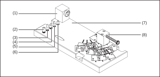
Testing / Straightening System /i
|
|
|
Testing / Straightening System /i
|
|
|
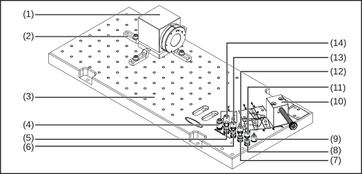
Scope of Delivery, Testing System /i G/W System
|
|
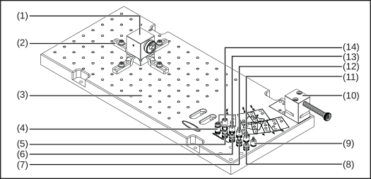
Scope of Delivery, Testing System /i G/W V
|
|
Fixing Set /i G/W TX
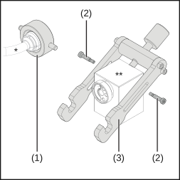
| (1) | Clamping bush |
| (2) | 2 shoulder bolts 6h8 M5 x 20 mm |
| (3) | Clamp |
| * | Torch body |
| ** | Torch body holder (included in the scope of delivery of the testing system) |
Straightening System /i
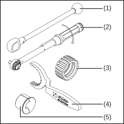
Straightening system /i - 44,0350,5241
| (1) | Straightening lever |
| (2) | Torque wrench |
| (3) | Union nut |
| (4) | Torch wrench |
| (5) | Straightening cup ø 16 mm Straightening cup ø 18 mm |
Check MTB R robot welding torch
Check MTB R robot welding torch with testing / straightening system /i
Preparing the testing unit
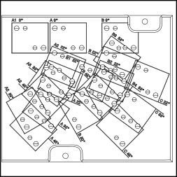
The base plate of the testing system /i contains various positions for mounting the testing unit.
The testing unit is pre-mounted on the 0° mounting position when delivered.
For every other torch body curvature, the testing unit must be mounted on the base plate according to the torch body curvature of the welding torch that is to be tested:
Name | Length (mm) | Length (inch) | Height (mm) | Height (inch) | Angle |
|---|---|---|---|---|---|
A 0° | 250 | 9.842 | 0 | 0 | 0° |
A 22° | 241 | 9.488 | 50 | 1.969 | 22° |
A 36° | 224 | 8.819 | 86 | 3.386 | 36° |
A 45° | 209 | 8.228 | 107 | 4.213 | 45° |
A1 0° | 187.5 | 7.382 | 0 | 0 | 0° |
A2 22° | 246 | 9.685 | 27 | 1.063 | 22° |
A2 45° | 228.5 | 8.996 | 56.5 | 2.224 | 45° |
A2 60° | 212 | 8.346 | 71 | 2.795 | 60° |
A3 36° | 236 | 9.291 | 44.5 | 1.752 | 36° |
B 0° | 335 | 13.189 | 0 | 0 | 0° |
B 22° | 331 | 13.032 | 27 | 1.063 | 22° |
B 45° | 313.5 | 12.342 | 56.5 | 2.224 | 45° |
B 60° | 297 | 11.692 | 71 | 2.795 | 60° |
B1 22° | 291 | 11.457 | 50 | 1.969 | 22° |
B2 22° | 325 | 12.795 | 50 | 1.969 | 22° |
B3 36° | 338 | 13.307 | 0 | 0 | 36° |
B4 36° | 321 | 12.638 | 44.5 | 1.752 | 36° |
C 22° | 383 | 15.079 | 50 | 1.969 | 22° |
C 36° | 366 | 14.409 | 86 | 3.386 | 36° |
C 45° | 351 | 13.819 | 107 | 4.134 | 45° |
1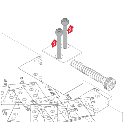
2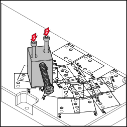
Check MTB R robot welding torch with testing / straightening system /i
Preparing the testing unit
The base plate of the testing system /i contains various positions for mounting the testing unit.
The testing unit is pre-mounted on the 0° mounting position when delivered.
For every other torch body curvature, the testing unit must be mounted on the base plate according to the torch body curvature of the welding torch that is to be tested:
Name | Length (mm) | Length (inch) | Height (mm) | Height (inch) | Angle |
|---|---|---|---|---|---|
A 0° | 250 | 9.842 | 0 | 0 | 0° |
A 22° | 241 | 9.488 | 50 | 1.969 | 22° |
A 36° | 224 | 8.819 | 86 | 3.386 | 36° |
A 45° | 209 | 8.228 | 107 | 4.213 | 45° |
A1 0° | 187.5 | 7.382 | 0 | 0 | 0° |
A2 22° | 246 | 9.685 | 27 | 1.063 | 22° |
A2 45° | 228.5 | 8.996 | 56.5 | 2.224 | 45° |
A2 60° | 212 | 8.346 | 71 | 2.795 | 60° |
A3 36° | 236 | 9.291 | 44.5 | 1.752 | 36° |
B 0° | 335 | 13.189 | 0 | 0 | 0° |
B 22° | 331 | 13.032 | 27 | 1.063 | 22° |
B 45° | 313.5 | 12.342 | 56.5 | 2.224 | 45° |
B 60° | 297 | 11.692 | 71 | 2.795 | 60° |
B1 22° | 291 | 11.457 | 50 | 1.969 | 22° |
B2 22° | 325 | 12.795 | 50 | 1.969 | 22° |
B3 36° | 338 | 13.307 | 0 | 0 | 36° |
B4 36° | 321 | 12.638 | 44.5 | 1.752 | 36° |
C 22° | 383 | 15.079 | 50 | 1.969 | 22° |
C 36° | 366 | 14.409 | 86 | 3.386 | 36° |
C 45° | 351 | 13.819 | 107 | 4.134 | 45° |
1
2
- Check MTB R robot welding torch
- Check MTB R robot welding torch with testing / straightening system /i
Preparing the testing unit
The base plate of the testing system /i contains various positions for mounting the testing unit.
The testing unit is pre-mounted on the 0° mounting position when delivered.
For every other torch body curvature, the testing unit must be mounted on the base plate according to the torch body curvature of the welding torch that is to be tested:
Name | Length (mm) | Length (inch) | Height (mm) | Height (inch) | Angle |
|---|---|---|---|---|---|
A 0° | 250 | 9.842 | 0 | 0 | 0° |
A 22° | 241 | 9.488 | 50 | 1.969 | 22° |
A 36° | 224 | 8.819 | 86 | 3.386 | 36° |
A 45° | 209 | 8.228 | 107 | 4.213 | 45° |
A1 0° | 187.5 | 7.382 | 0 | 0 | 0° |
A2 22° | 246 | 9.685 | 27 | 1.063 | 22° |
A2 45° | 228.5 | 8.996 | 56.5 | 2.224 | 45° |
A2 60° | 212 | 8.346 | 71 | 2.795 | 60° |
A3 36° | 236 | 9.291 | 44.5 | 1.752 | 36° |
B 0° | 335 | 13.189 | 0 | 0 | 0° |
B 22° | 331 | 13.032 | 27 | 1.063 | 22° |
B 45° | 313.5 | 12.342 | 56.5 | 2.224 | 45° |
B 60° | 297 | 11.692 | 71 | 2.795 | 60° |
B1 22° | 291 | 11.457 | 50 | 1.969 | 22° |
B2 22° | 325 | 12.795 | 50 | 1.969 | 22° |
B3 36° | 338 | 13.307 | 0 | 0 | 36° |
B4 36° | 321 | 12.638 | 44.5 | 1.752 | 36° |
C 22° | 383 | 15.079 | 50 | 1.969 | 22° |
C 36° | 366 | 14.409 | 86 | 3.386 | 36° |
C 45° | 351 | 13.819 | 107 | 4.134 | 45° |
1
2
- Check MTB R robot welding torch
- Check MTB R robot welding torch with testing / straightening system /i
Preparing the torch body for testing
1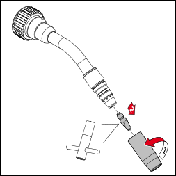
2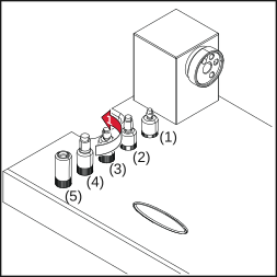
(1) ... M6 (2) ... M8 (3) ... M8x1.5 (4) ... M10x1.25
(5) ... M10x1.25 Contec
(5) ... M10x1.25 Contec
3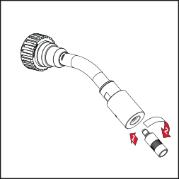
- Check MTB R robot welding torch
- Check MTB R robot welding torch with testing / straightening system /i
Checking the torch body
1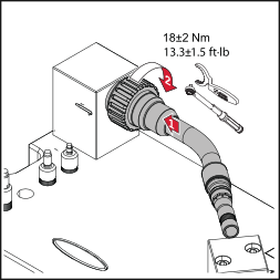
2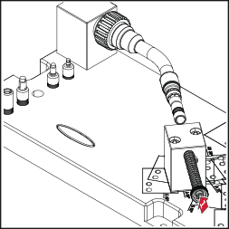
NOTE!
The torch body is okay if
The dowel pin glides fully into the centering sleeve with ease
The dowel pin glides out of the centering sleeve with ease after the spring is released due to the spring force
If the dowel pin cannot easily be moved into or out of the centering sleeve, set up the torch body according to the chapter "Set up MTB R robot welding torch" (from page (→)).
IMPORTANT! For dimensional deviations > 5 mm, you should no longer set up the torch body on your own. Send torch body to Fronius for repair.
Check MTB R robot welding torch complete systems with testing system /i G/W System
General
With the testing system /i G/W System you can check complete robot welding torch systems from torch body to CrashBox for dimensional deviations.
The user is responsible for the setup and initial adjustment.
There are various possibilities available for testing, e.g.:
- Torch body
- Torch body + hosepack
- Torch body + hosepack + clamp
- Torch body + hosepack + clamp + CrashBox
- Check MTB R robot welding torch
- Check MTB R robot welding torch complete systems with testing system /i G/W System
General
With the testing system /i G/W System you can check complete robot welding torch systems from torch body to CrashBox for dimensional deviations.
The user is responsible for the setup and initial adjustment.
There are various possibilities available for testing, e.g.:
- Torch body
- Torch body + hosepack
- Torch body + hosepack + clamp
- Torch body + hosepack + clamp + CrashBox
- Check MTB R robot welding torch
- Check MTB R robot welding torch complete systems with testing system /i G/W System
Preparing the Testing System /i G/W System and Torch Body of the Complete System
1Check torch body of the complete system using a suitable testing system
The base plate of the testing system /i G/W contains a wide range of positions for mounting the testing unit.
The testing unit is pre-mounted on the 0° mounting position when delivered.
For every other torch neck curvature, the testing unit must be mounted on the base plate according to the torch neck curvature of the welding torch that is to be tested:
2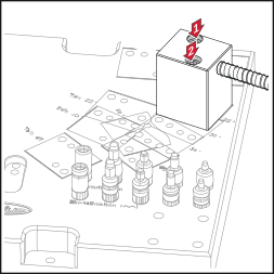
3
NOTE!
To distinguish between centering sleeve (2) and adjusting sleeve (1), the adjusting sleeves are equipped with two additional cross grooves.
4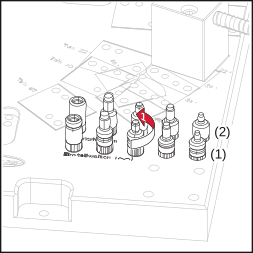
Unscrew adjusting sleeve
5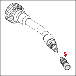
The mounting block is designed for mounting various robot shutoff boxes.
6
Mount the complete system on the mounting block
- Check MTB R robot welding torch
- Check MTB R robot welding torch complete systems with testing system /i G/W System
Calibrating the Testing System /i G/W System
1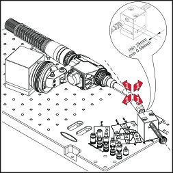
2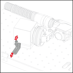
3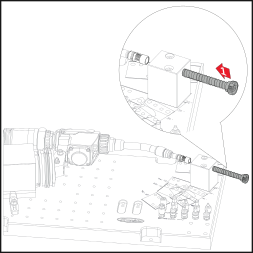
The dowel pin must fully glide into the adjusting sleeve with ease.
The dowel pin must glide out of the adjusting sleeve with ease after the spring is released due to the spring force.
If the dowel pin doesn’t glide into the adjusting sleeve or only does so with difficulty, the complete system with mounting block must be readjusted.
4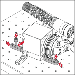
5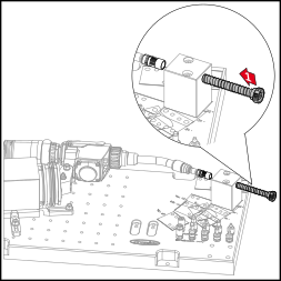
If the dowel pin doesn’t glide into the adjusting sleeve or only does so with difficulty, the complete system with mounting block must be readjusted.
- Check MTB R robot welding torch
- Check MTB R robot welding torch complete systems with testing system /i G/W System
Checking the Complete System
NOTE!
The hosepack must be released during checking.
If the hosepack is not released the robot shut off box may be misaligned.
NOTE!
To distinguish between centering sleeve (2) and adjusting sleeve (1), the adjusting sleeves are equipped with two additional cross grooves.
1
2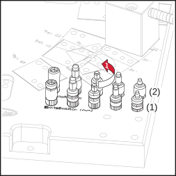
Unscrew centering sleeve.
3
4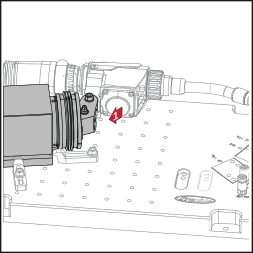
Mount the complete system on the mounting block
5
NOTE!
The complete system is okay if
the dowel pin glides fully into the centering sleeve with ease, and
the dowel pin glides out of the centering sleeve with ease after the spring is released due to the spring force.
If the dowel pin does not easily glide into or out of the centering sleeve, the complete system must be adjusted (e.g. at the clamp).
Check customer-specific robot welding torch with testing system /i G/W
General
With the testing system /i G/W V, you can check customer-specific robot welding torch systems and special models for dimensional deviations.
The user is responsible for the setup and initial adjustment.
- Check MTB R robot welding torch
- Check customer-specific robot welding torch with testing system /i G/W
General
With the testing system /i G/W V, you can check customer-specific robot welding torch systems and special models for dimensional deviations.
The user is responsible for the setup and initial adjustment.
- Check MTB R robot welding torch
- Check customer-specific robot welding torch with testing system /i G/W
Preparing the testing system /i G/W V and torch body
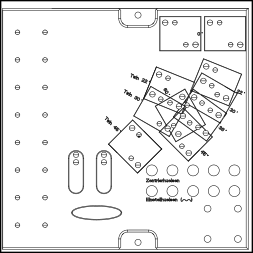
The base plate of the testing system /i G/W V contains various positions for mounting the testing unit.
The testing unit is pre-mounted on the 0° mounting position when delivered.
For every other torch body curvature, the testing unit must be mounted on the base plate according to the torch body curvature of the welding torch that is to be tested:
1
2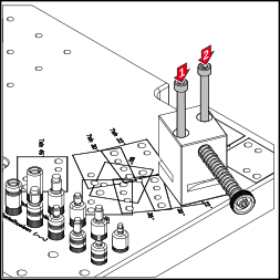
3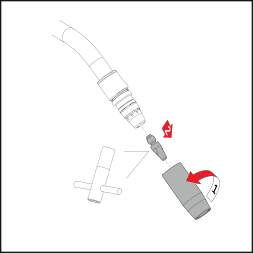
NOTE!
To distinguish between centering sleeve (2) and adjusting sleeve (1), the adjusting sleeves are equipped with two additional cross grooves.
4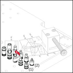
Unscrew adjusting sleeve
5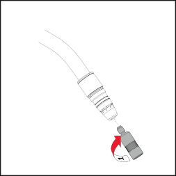
6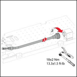
- Check MTB R robot welding torch
- Check customer-specific robot welding torch with testing system /i G/W
Calibrating the Testing System /i G/W V
1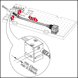
2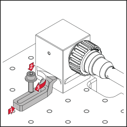
3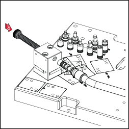
The dowel pin must fully glide into the adjusting sleeve with ease.
The dowel pin must glide out of the adjusting sleeve with ease after the spring is released due to the spring force.
If the dowel pin doesn’t glide into the adjusting sleeve or only does so with difficulty, the torch body holder with torch body must be readjusted.
4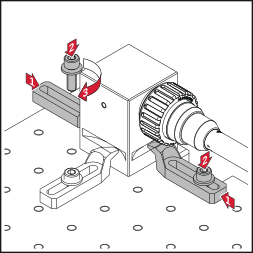
5
If the dowel pin doesn’t glide into the adjusting sleeve or only does so with difficulty, the torch body holder with torch body must be readjusted.
- Check MTB R robot welding torch
- Check customer-specific robot welding torch with testing system /i G/W
Checking the Customer-Specific Robot Welding Torches
1
NOTE!
To distinguish between centering sleeve (2) and adjusting sleeve (1), the adjusting sleeves are equipped with two additional cross grooves.
2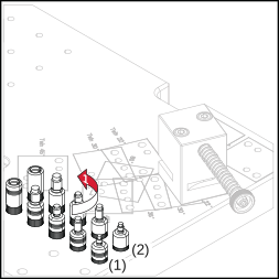
Unscrew centering sleeve.
3
Check TX robot welding torches with fixing system /i G/W TX
General
The fixing set /i G/W TX is an add-on for checking TX robot welding torches and is used in conjunction with the following testing systems:
- Testing/straightening system /i (44,0360,0073)
- Testing system /i G/W V (44,0360,0012)
Testing units are assembled as described.
Afterwards, the fixing set /i G/W TX and the TX robot welding torch are mounted on the torch body holder.
The testing process is then carried out according to the respective testing system.
General
The fixing set /i G/W TX is an add-on for checking TX robot welding torches and is used in conjunction with the following testing systems:
- Testing/straightening system /i (44,0360,0073)
- Testing system /i G/W V (44,0360,0012)
Testing units are assembled as described.
Afterwards, the fixing set /i G/W TX and the TX robot welding torch are mounted on the torch body holder.
The testing process is then carried out according to the respective testing system.
Preparing the Testing Unit and Torch Body
Mounting the fixing set /i G/W TX and TX robot welding torch onto the torch body holder
1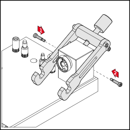
2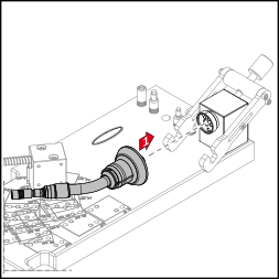
3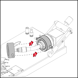
4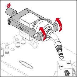
5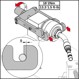
Use torque wrench!
Set up MTB R robot welding torch
Set up robot welding torch
Preparing the Torch Body for Setup
1
2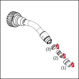
3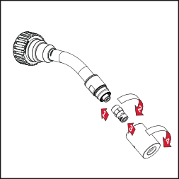
Screw in nozzle fitting replacement and straightening sleeve
4
Unscrew centering sleeve
(1) ... M6 (2) ... M8 (3) ... M8x1.5 (4) ... M10x1.25
(5) ... M10x1.25 Contec
(1) ... M6 (2) ... M8 (3) ... M8x1.5 (4) ... M10x1.25
(5) ... M10x1.25 Contec
5
Screw in centering sleeve
Set up robot welding torch
Preparing the Torch Body for Setup
1
2
3
Screw in nozzle fitting replacement and straightening sleeve
4
Unscrew centering sleeve
(1) ... M6 (2) ... M8 (3) ... M8x1.5 (4) ... M10x1.25
(5) ... M10x1.25 Contec
(1) ... M6 (2) ... M8 (3) ... M8x1.5 (4) ... M10x1.25
(5) ... M10x1.25 Contec
5
Screw in centering sleeve
Preparing the Torch Body for Setup
1
2
3
Screw in nozzle fitting replacement and straightening sleeve
4
Unscrew centering sleeve
(1) ... M6 (2) ... M8 (3) ... M8x1.5 (4) ... M10x1.25
(5) ... M10x1.25 Contec
(1) ... M6 (2) ... M8 (3) ... M8x1.5 (4) ... M10x1.25
(5) ... M10x1.25 Contec
5
Screw in centering sleeve
Setting up the torch body
Preparation:
1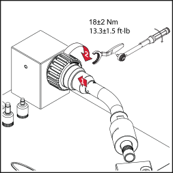
2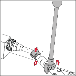
* The straightening cups are only required for setup at the outer tube.
3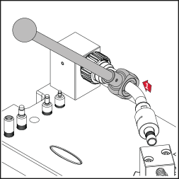
To set up at the outer tube, push the straightening lever over the straightening cups
4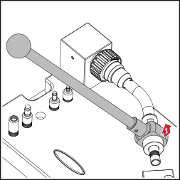
Position straightening lever above straightening sleeve
Set up torch body horizontally and/or vertically:
5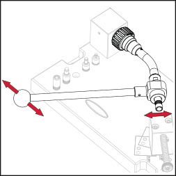
Set up horizontally
6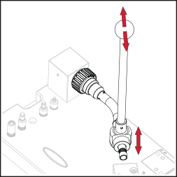
Set up vertically
7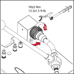
Loosen union nut and re-tighten
8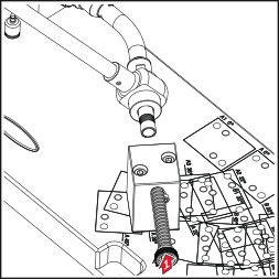
Check the torch body
NOTE!
The torch body is okay if
The dowel pin glides fully into the centering sleeve with ease
The dowel pin glides out of the centering sleeve with ease after the spring is released due to the spring force
If the dowel pin does not easily glide into or out of the centering sleeve, the torch body must be readjusted.
IMPORTANT! For dimensional deviations > 5 mm, you should no longer set up the torch body on your own. Send torch body to Fronius for repair.
Final tasks
If the torch body is okay:
1Remove straightening lever
2Loosen union nut
3Remove the torch body from the testing system
4Unscrew straightening sleeve from the torch body
5Unscrew centering sleeve from the torch body
6Remove nozzle fitting replacement
7Mount wearing parts on the torch body according to the Operating Instructions of the welding torch
Set up customer-specific robot welding torch with testing system /i G/W V
General
The testing system /i G/W V is also designed to set up customer-specific welding torches.
- Set up MTB R robot welding torch
- Set up customer-specific robot welding torch with testing system /i G/W V
General
The testing system /i G/W V is also designed to set up customer-specific welding torches.
- Set up MTB R robot welding torch
- Set up customer-specific robot welding torch with testing system /i G/W V
Preparing the Torch Body for Setup
1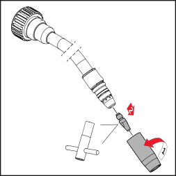
2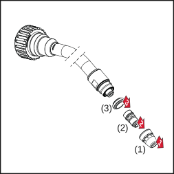
3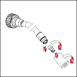
Screw in nozzle fitting replacement and straightening sleeve
4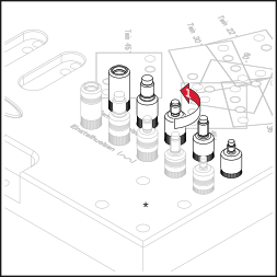
Unscrew centering sleeve
* Torch body holder not shown
* Torch body holder not shown
5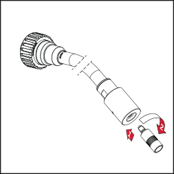
Screw in centering sleeve
- Set up MTB R robot welding torch
- Set up customer-specific robot welding torch with testing system /i G/W V
Preparing the Testing System /i G/W V
1
- Set up MTB R robot welding torch
- Set up customer-specific robot welding torch with testing system /i G/W V
Mounting the Torch Body Holder
1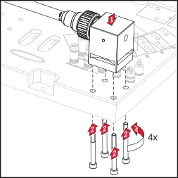
- Set up MTB R robot welding torch
- Set up customer-specific robot welding torch with testing system /i G/W V
Mounting the Testing Unit
1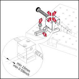
Align testing unit to torch body and fix lightly with a clamp
2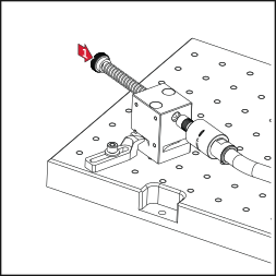
Check the torch body
3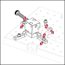
Fix testing unit with the remaining clamps
4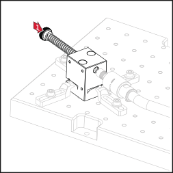
Check the torch body
- Set up MTB R robot welding torch
- Set up customer-specific robot welding torch with testing system /i G/W V
Setting up Customer-Specific Robot Welding Torch
NOTE!
For the setup of the welding torch
the torch body holder must be mounted with four screws at the adjustment / centering sleeves on the testing system /i G/W V,
the welding torch must be mounted on the torch body holder.