Warnings are intended to warn people of possible injury and to prevent personal injury and damage to the product. They relate to individual actions performed with and on the product.
DANGER!
Indicates an immediately dangerous situation.
Serious injury or death will result if the hazard is not avoided.
Action step to escape the situation.
WARNING!
Indicates a potentially dangerous situation.
Serious injury or death will potentially result if the hazard is not avoided.
Action step to escape the situation.
CAUTION!
Indicates a potentially dangerous situation.
Minor or moderate injury may result if the hazard is not avoided.
Action step to escape the situation.
NOTE!
Indicates a situation which may result in damage to property.
Failure to avoid the situation may result in impaired work results and material damage to the product or other property.
Action step to avoid the situation.
Safety instructions are intended to ensure safe use of the product. They are preventive and help to inform users about basic risks when using the product. They do not refer specifically to individual actions performed with and on the product.
Warnings are intended to warn people of possible injury and to prevent personal injury and damage to the product. They relate to individual actions performed with and on the product.
DANGER!
Indicates an immediately dangerous situation.
Serious injury or death will result if the hazard is not avoided.
Action step to escape the situation.
WARNING!
Indicates a potentially dangerous situation.
Serious injury or death will potentially result if the hazard is not avoided.
Action step to escape the situation.
CAUTION!
Indicates a potentially dangerous situation.
Minor or moderate injury may result if the hazard is not avoided.
Action step to escape the situation.
NOTE!
Indicates a situation which may result in damage to property.
Failure to avoid the situation may result in impaired work results and material damage to the product or other property.
Action step to avoid the situation.
Safety instructions are intended to ensure safe use of the product. They are preventive and help to inform users about basic risks when using the product. They do not refer specifically to individual actions performed with and on the product.
The device is manufactured using state-of-the-art technology and according to recognised safety standards. If used incorrectly or misused, however, it can cause:- injury or death to the operator or a third party,
- damage to the device and other material assets belonging to the operating company,
- inefficient operation of the device.
- be suitably qualified,
- have sufficient knowledge of welding and
- read and follow these operating instructions carefully.
The operating instructions must always be at hand wherever the device is being used. In addition to the operating instructions, attention must also be paid to any generally applicable and local regulations regarding accident prevention and environmental protection.
All safety and danger notices on the device - must be in a legible state,
- must not be damaged,
- must not be removed,
- must not be covered, pasted or painted over.
For the location of the safety and danger notices on the device, refer to the section headed "General" in the operating instructions for the device.
Before switching on the device, rectify any faults that could compromise safety.
The device is to be used exclusively for its intended purpose. Utilization for any other purpose, or in any other manner, shall be deemed to be not in accordance with the intended use.
Intended use also means:- Reading and adhering to all instructions in the operating instructions
- Carefully reading and obeying all safety instructions and danger notices
Only operate the device with the welding machines provided for this purpose.
The device is designed for commercial and industrial use. The manufacturer shall not be liable for any damage resulting from use in a residential area.
Operation or storage of the device outside the stipulated area will be deemed as not in accordance with the intended purpose.
Ambient temperature range:- during operation: -10°C to + 50°C (14°F to 122°F)
- during transport and storage: -15°C to +70°C (5°F to 158°F)
- up to 50 % at 40 °C (104 °F)
- up to 90 % at 20 °C (68 °F)
The surrounding air must be free from dust, acids, corrosive gases or substances, etc.
Can be used at altitudes of up to 2000 m (6500 ft)
The operator must only allow persons to work with the device who: - are familiar with the fundamental instructions regarding safety at work and accident prevention and have been instructed in how to use the device
- have read and understood these operating instructions, especially the section "safety rules", and have confirmed as much with their signatures
- are trained to produce the required results.
Checks must be carried out at regular intervals to ensure that operators are working in a safety-conscious manner.
Before using the device, all persons instructed to do so must:- observe the basic instructions regarding safety at work and accident prevention; and
- read these operating instructions (especially the "Safety rules" section) and sign to confirm that they have understood them and will follow them.
Before leaving the workplace, ensure that people or property cannot come to any harm in your absence.
Devices in emission class A:- Are only designed for use in industrial settings
- Can cause line-bound and radiated interference in other areas
- Satisfy the emissions criteria for residential and industrial areas. This is also true for residential areas in which the energy is supplied from the public low-voltage mains.
EMC device classification as per the rating plate or technical data.
In certain cases, even though a device complies with the standard limit values for emissions, it may affect the application area for which it was designed (e.g. when there is sensitive equipment at the same location, or if the site where the device is installed is close to either radio or television receivers).
If this is the case, then the operator is obliged to take appropriate action to rectify the situation.
Check and evaluate the immunity to interference of nearby devices according to national and international regulations. Examples of equipment that may be susceptible to interference from the device include:- Safety devices
- Network, signal and data transfer lines
- IT and telecommunications devices
- Measuring and calibrating devices
- Mains supply
- If electromagnetic interference arises despite the correct mains connection, additional measures are necessary (e.g. use of a suitable line filter)
- Welding power-leads
- must be kept as short as possible
- must be laid close together (to avoid EMF problems)
- must be kept well apart from other leads
- Equipotential bonding
- Earthing of the workpiece
- If necessary, establish an earth connection using suitable capacitors.
- Shield, if necessary
- Shield other devices nearby
- Shield the entire welding installation
- Effects on the health of persons in the vicinity, e.g. those with pacemakers and hearing aids
- Individuals with pacemakers must seek advice from their doctor before approaching the device or any welding that is in progress
- For safety reasons, maintain as large a distance as possible between the welding power-leads and the head/torso of the welder
- Do not carry welding power-leads and hosepacks over the shoulders or wind them around any part of the body
- The maximum permissible tilt angle is 10°.
- Observe relevant national and international regulations.
Use internal directives and checks to ensure that the workplace environment is always clean and clearly laid out.
Only set up and operate the device in accordance with the degree of protection shown on the rating plate.
When setting up the device, ensure there is an all-round clearance of 0.5 m (1 ft. 7.69 in.) to ensure that cooling air can flow in and out freely.
When transporting the device, observe the relevant national and local guidelines and accident prevention regulations. This applies especially to guidelines regarding the risks arising during transport.
Do not lift or transport operational devices. Switch off and disconnect devices from the grid before transport or lifting.
After transporting the device, the device must be visually inspected for damage before commissioning. Any damage must be repaired by trained service technicians before commissioning the device.
It is impossible to guarantee that bought-in parts are designed and manufactured to meet the demands made of them, or that they satisfy safety requirements.
- Use only original spare and wearing parts (also applies to standard parts).
- Do not carry out any modifications, alterations, etc. to the device without the manufacturer's consent.
- Components that are not in perfect condition must be replaced immediately.
- When ordering, please give the exact designation and part number as shown in the spare parts list, as well as the serial number of your device.
The housing screws provide the ground conductor connection for earthing the housing parts.
Only use original housing screws in the correct number and tightened to the specified torque.
Devices with the CE mark meet the requirements of all valid EU directives, such as:- Directive 2014/30/EU on Electromagnetic Compatibility
- Directive 2014/35/EU Low Voltage Directive
- Directive 2014/53/EU Radio Equipment Directive
- EN IEC 60974 Arc welding equipment
- And so on
The full text of the EU Declaration of Conformity can be found at
https://www.fronius.com .
Devices with the CSA mark satisfy the requirements of the relevant standards in Canada and the USA.
With regard to data security, the user is responsible for:- backing up any changes made to the factory settings
- saving and retaining personal settings
Copyright of this document remains with Fronius International GmbH.
Text, illustrations and other media correspond to the technical state of the art at the time of publication. Fronius reserves the right to make changes. If you have any suggestions for improvement, or can point out any inconsistencies in this document, we will be most grateful for your comments.
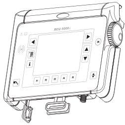
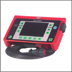
RCU 5000i remote control
The RCU 5000i remote control is intended for the operation of all power sources in the TransSynergic/TransPuls Synergic series. All functions available on the power source can be retrieved using the RCU 5000i. In addition, further functions are available such as optimisation of welding characteristics.
Connection to the power source takes place via a LocalNet plug.
The RCU 5000i remote control unit is equipped with an LCD. In conjunction with a clearly laid-out menu, this makes for a user-friendly device.
RCU 5000i remote control
The RCU 5000i remote control is intended for the operation of all power sources in the TransSynergic/TransPuls Synergic series. All functions available on the power source can be retrieved using the RCU 5000i. In addition, further functions are available such as optimisation of welding characteristics.
Connection to the power source takes place via a LocalNet plug.
The RCU 5000i remote control unit is equipped with an LCD. In conjunction with a clearly laid-out menu, this makes for a user-friendly device.
- for operating and programming the power sources, making pre-settings,
- in robot applications,
- for manual welding using power sources equipped with the "Remote" control panel.
- Clear layout thanks to LCD
- Simple and logical operation
- 180 pre-programmed Synergic welding characteristics
- Welding characteristics can be optimised
- Easy to program jobs
- Up to 1000 jobs can be stored
- User access management using keycard
- Parameter monitoring thanks to QMaster function
- LocalNet connection
- USB interface for software updates
- Connected to the remote control: 1x remote control cable, 6-pin, 5 m (16 ft. 5 in.), incl. LocalNet plug, 10-pin
- 1x USB cable, approx. 1.8 m (5 ft. 11 in.), incl. USB adapter
- 1x memory card, 3.3 V
- 1x transponder card ("key card")
- 1x CD-ROM "software tools"
RCU 5000i bracket
The RCU 5000i bracket is intended for mounting on a wall or a remote power source. The remote control unit can be hung onto the RCU 5000i bracket.
Supply voltage | 24 V DC |
Current input | 170 mA |
Degree of protection | IP 23 |
Mark of conformity | CE, FCC |
Frequency band | 134,2 kHz |
Max. transmission power | < 65dBµA/m @10m |
Dimensions l / w / h | 258 / 180 / 48 mm
10.16 / 7.09 / 1.89 in. |
Weight | 1.5 kg
3.31 lb |
The RCU 5000i remote control is fitted with an RFID module (Radio Frequency Identification). The RFID module is for wireless and non-contact data transmission using the keycard (transponder card). Data transmission takes place via a magnetic field.
In the USA, RFID modules are subject to FCC certification: |
| FCC ID: QKWRF5000I |
NOTE!
Owing to software updates, you may find that your machine has certain functions that are not described in these operating instructions.
Moreover, illustrations in these instructions may differ slightly from the actual data displayed on the LCD.
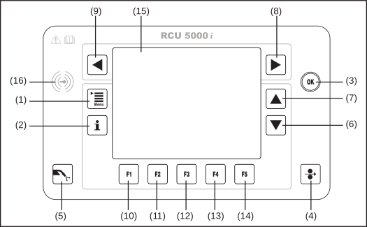
Action keys |
|---|
(1) | Menu key ... for calling up the main menu |
(2) | Info key ... for displaying context-specific information |
(3) | OK key ... for confirming menu dialogs, precautionary queries, etc. |
(4) | Feeder inching button ... for feeding the filler wire with no accompanying flow of gas or current |
(5) | Gas test button ... for checking the gas flow |
Navigation keys |
|---|
(6) | Down arrow key ... for scrolling through a list |
(7) | Up arrow key ... for scrolling through a list |
(8) | Right arrow key ... for sideways scrolling (e.g. in the "clothesline") |
(9) | Left arrow key ... for sideways scrolling (e.g. in the "clothesline") |
Function keys with varying functions |
|---|
(10) | F1 ... function key |
(11) | F2 key ... function key |
(12) | F3 key ... function key |
(13) | F4 key ... function key |
(14) | F5 key ... function key |
The current function is displayed on the LCD directly above the relevant function key.
Miscellaneous |
|---|
(15) | Display ... black/white LCD |
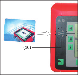
(16) | Keycard reader ... for identifying different access rights granted by means of a keycard |
Action keys |
|---|
(1) | Menu key ... for calling up the main menu |
(2) | Info key ... for displaying context-specific information |
(3) | OK key ... for confirming menu dialogs, precautionary queries, etc. |
(4) | Feeder inching button ... for feeding the filler wire with no accompanying flow of gas or current |
(5) | Gas test button ... for checking the gas flow |
Navigation keys |
|---|
(6) | Down arrow key ... for scrolling through a list |
(7) | Up arrow key ... for scrolling through a list |
(8) | Right arrow key ... for sideways scrolling (e.g. in the "clothesline") |
(9) | Left arrow key ... for sideways scrolling (e.g. in the "clothesline") |
Function keys with varying functions |
|---|
(10) | F1 ... function key |
(11) | F2 key ... function key |
(12) | F3 key ... function key |
(13) | F4 key ... function key |
(14) | F5 key ... function key |
The current function is displayed on the LCD directly above the relevant function key.
Miscellaneous |
|---|
(15) | Display ... black/white LCD |
(16) | Keycard reader ... for identifying different access rights granted by means of a keycard |
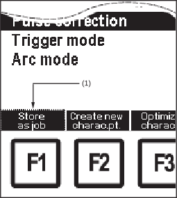
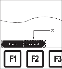
The OK key (3) aids the user in selecting the various function key functions.
If there is a border around a function key function, this function can be selected by pressing OK (3).
Example: border around F1 "Store as job"
Example: border around F2 "Forward"
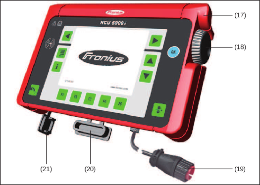
RCU 5000i front view - controls, connections
(17) | Receptor for bracket ... for hanging onto the wall bracket or the power source bracket |
(18) | Adjusting dial ... for adjusting parameters |
(19) | LocalNet plug with connection cable ... for connecting to the power source. The plug serves as a separation device and must be freely accessible |
(20) | Rubber cover ... for protecting the memory card slot |
(21) | Rubber cover ... for protecting the USB-PC connection point |
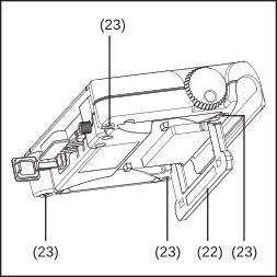
RCU 5000i rear view - controls, mechanical components
(22) | Bracket ... 0-95° hinged holder and stand |
(23) | M5 threaded insert ... e.g. for fixing to the wall |
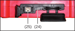
RCU 5000i side view - connections
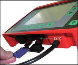
(24) | Memory card slot |
(25) | USB port... for connecting to a PC, e.g. for software updates |
Operation instructions for the RCU 5000i remote control unit are divided according to activities.
A distinction is made between the following activities:
- Welding (MIG/MAG Synergic, MIG/MAG manual, MMA, TIG and Job)
- Creating jobs
- Creating one's own characteristics and characteristic points
- Optimising and managing jobs
- Optimising and managing available characteristics
- Making presettings for the welding process
- Language and units of measurement - definitions
Operation instructions for the RCU 5000i remote control unit are divided according to activities.
A distinction is made between the following activities:
- Welding (MIG/MAG Synergic, MIG/MAG manual, MMA, TIG and Job)
- Creating jobs
- Creating one's own characteristics and characteristic points
- Optimising and managing jobs
- Optimising and managing available characteristics
- Making presettings for the welding process
- Language and units of measurement - definitions
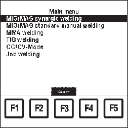
Main menu display
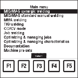
The individual activities are highlighted in the main menu. The main menu is called up by pressing the menu key (1).
A "clothesline" is assigned to every menu item.
- Individual welding parameters are collected together in various data records.
- These data records are arranged in a loop ("clothesline").
- Within the clothesline, the user can navigate in two directions.
- After the last data record, the first data record appears. If navigating in the opposite direction, the last data record appears after the first.
- The number of data records varies. Due to certain parameters or special functions on the power source, data records may be added to the clothesline.
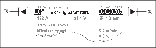
Example of "clothesline" with 5 data records (A - E) - "Working parameters" open
- - All parameters, displays and functions required for a selected activity are sorted according to the order in the "clothesline".
- Every data record in a "clothesline" is displayed in its own screen.
Throughout the rest of the operating instructions the data records are shown as in the example below:
| Screen | Screen (for data record) |
| "Working parameters" | Screen title data record) |
- Options and special functions on the power source (e.g. SynchroPulse) are hung on the data records available on a "clothesline".
- Navigate within the "clothesline" by pressing the navigation keys right (8) and left (9).
Adjusted values need not be saved or stored. The values are immediately active.
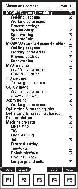
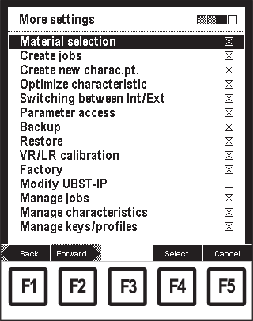
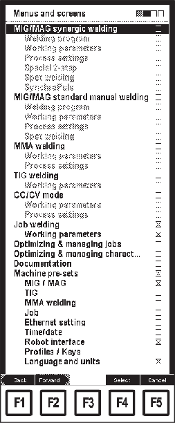
The RCU 5000i remote control unit uses various displays while operating. These so-called screens are called up using the menu, and serve as dialog with the user.
The RCU 5000i remote control unit uses various displays while operating. These so-called screens are called up using the menu, and serve as dialog with the user.
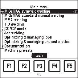
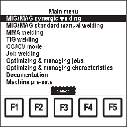
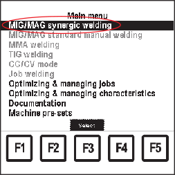
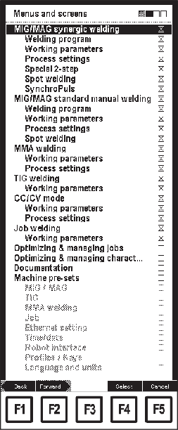
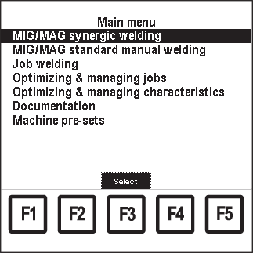
The "Menu" screen shows the main menu. To call up the "Menu" screen, press the Menu key (1).
NOTE!
Once the Menu key (1) is pressed, all open dialogs are cancelled without asking for confirmation, with the exception of wizards.
"Menu" screen
| (1) | Menu items |
| (2) | MIG/MAG synergic welding menu item selected |
| (3) | F3 "Select" |
- A "Data" screen appears if a menu item is selected in the main menu.
- Each "Data" screen contains a "clothesline".
- Many different "Data" screens can be displayed within one menu item.
By using special functions on the power source or certain parameter settings, further "Data" screens can be hung onto the relevant "clothesline". - In the "Data" screens, parameters can be set or viewed. The parameters are represented in a list.
Parameters are selected using the down and up navigation keys (6) and (7).
Parameter values are set using the adjusting dial (18)
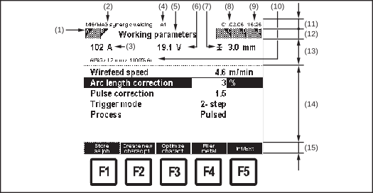
(1) | Screen identifying character | | (9) | Time |
(2) | Activity | | (10) | Filler metal, wire diameter, shielding gas |
(3) | Welding current | | (11) | Information line |
(4) | User | | (12) | Clothesline with screens A-E |
(5) | Screen title | | (13) | Display area |
(6) | Welding voltage | | (14) | Parameter list |
(7) | Sheet thickness | | (15) | Function key functions |
(8) | Date | | | - F1 "Store as job"
- F2 "Create new characteristic point"
- F3 "Optimize characteristic"
- F4 "Filler metal"
- F5 "Internal/External"
|
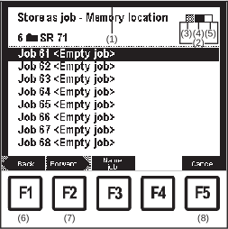
Wizard refers to a guided input sequence. The user can move forwards or backwards within the sequence. Various screens appear within a wizard.
Example: "Wizard" screen
| (1) | Dark border |
| (2) | Processing step |
| (3) | Completed steps |
| (4) | Current step |
| (5) | Step still live |
| (6) | F1 "Back" (in grey in the first screen) |
| (7) | F2 "Forward" (or "Done" in the final screen) |
| (8) | F5 "Cancel" |
The "Dialogue" screen is used for showing subdialogues.
The "Dialogue" screen may contain hierarchical structures, pick lists, etc.
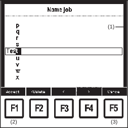
Example: "Dialogue" screen with "Accept" and "Cancel"
| (1) | Dark border |
| (2) | F1 "Accept" |
| (3) | F5 "Cancel" |
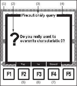
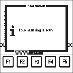
The "Message" screen displays certain statuses. The message must be acknowledged, or a decision must be taken.
The "Message" screen appears in front of part of the current screen. This makes the current screen turn grey.
Example: "Message" screen - Precautionary query
| (1) | Current screen, shown in grey |
| (2) | Symbol |
| (3) | Message type |
| (4) | Dark border |
| (5) | F2 "Yes" |
| (6) | F3 "No" |
| (7) | F4 "Cancel" |
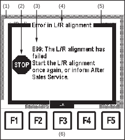
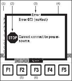
"Error" screens display errors that have occurred during welding. "Error" screens must be reset. If an "Error" screen is ignored, it reappears after 2 minutes for as long as the error persists. "Error" screens appear in front of part of the current screen. This makes the current screen turn grey.
Example: "Error" screen
| (1) | Current screen, shown in grey |
| (2) | Symbol |
| (3) | Error code |
| (4) | Error description |
| (5) | Dark border |
| (6) | F3 "OK" |
Example: "Error" screen with function keys "Reset" and "Ignore"
| (1) | Current screen, shown in grey |
| (2) | Symbol |
| (3) | Error description |
| (4) | Dark border |
| (5) | F2 "Reset" |
| (6) | F3 "Ignore" |
WARNING!
Danger due to incorrect operation and incorrectly performed work.
This can result in serious injury and damage to property.
All the work and functions described in this document must only be carried out by trained and qualified personnel.
Read and understand this document.
Read and understand all the Operating Instructions for the system components, especially the safety rules.
WARNING!
Danger due to incorrect operation and incorrectly performed work.
This can result in serious injury and damage to property.
All the work and functions described in this document must only be carried out by trained and qualified personnel.
Read and understand this document.
Read and understand all the Operating Instructions for the system components, especially the safety rules.
The following firmware is required on the power source to be able to operate the RCU 5000i remote control unit:
OFFICIAL UST V 3.20.1
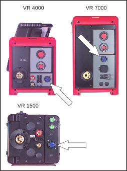
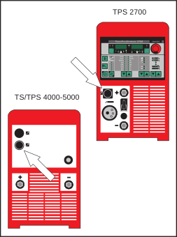
The RCU 5000i remote control unit can be connected to any LocalNet socket on the welding machine, e.g.:
LocalNet connection socket on VR 4000, VR 7000 and VR 1500
LocalNet connection socket on TPS 2700 and TS/TPS 4000-5000
Procedure:1Switch the power source mains switch to the “0” position
2Plug the remote control unit LocalNet plug into the LocalNet connection socket
3Tighten the union nut on the plug
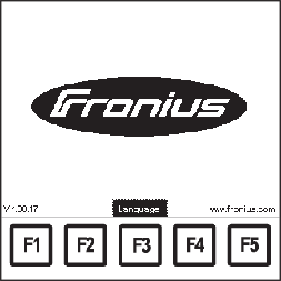
4Move the power source mains switch to the "I" position - the remote control is ready, the starting sequence appears
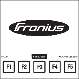
The following appear on the display during the starting sequence:- Fronius logo (centre)
- Software version (bottom left)
- www.fronius.com (bottom right)
- language (F3 key)
The starting sequence lasts approx. 2 seconds. The language and units (metric or imperial) can be preset during this time. To do this, press F3.
Starting sequence, F3 "Language"
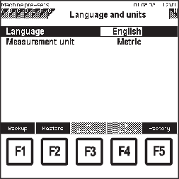
1To preset the language and measurement units, press F3 "Language"- Machine pre-sets "Language and units" screen appears
Machine pre-sets: "Language and units" screen, language selected
2Select the corresponding parameters using down (6) or up (7) keys
3Alter the parameter value with the adjusting dial (18)
4Press the "Menu" button (1)
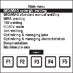
Main menu in the selected language
Main menu appears in the selected language
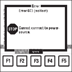
"Error 073 (no Host)" screen
The non-resettable error "073 (no Host)" appears if the remote control cannot connect to the power source during commissioning.
Possible causes are, for example, poor contact with the power source or incorrect LocalNet distributor.
Once an active link is established, error "073 (no Host)" disappears.
The error "073 (no Host)" can be ignored.
NOTE!
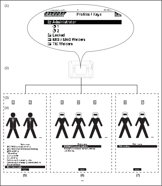
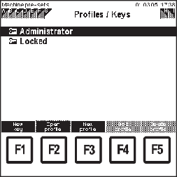
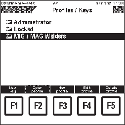
The key card can be used for locking and unlocking the remote control, as long as there are no profiles or keys apart from "Administrator" and "Locked" in the "Machine pre-sets" menu item.
NOTE!
The key card can be used for locking and unlocking the remote control, as long as there are no profiles or keys apart from "Administrator" and "Locked" in the "Machine pre-sets" menu item.
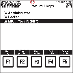
More information about user management, profiles or keys can be found in the "Machine pre-sets" chapter, "Profiles / Keys" section.
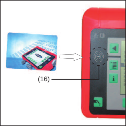
Holding the keycard up to the keycard reader
1Hold the keycard up to the keycard reader (16)
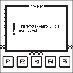
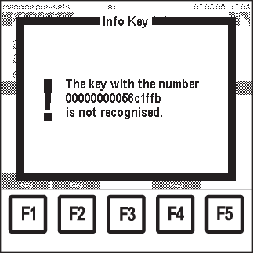
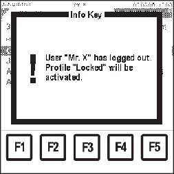
"Info Key - The remote control unit is now locked" screen
The "Info Key - The remote control unit is now locked " screen appears
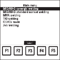
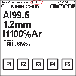
Main menu in the "Locked" profile
The "Locked" profile is called up.
NOTE!
The properties in the "Locked" profile can be altered in the "Machine pre-sets" menu item, in the "Profiles / Keys" screen.
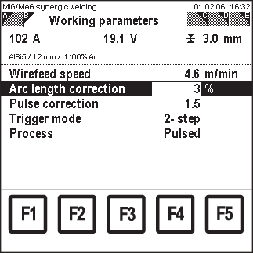
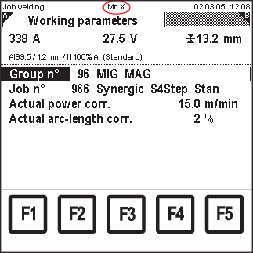
"MIG/MAG synergic welding" menu item in locked remote control, "Working parameters" screen
Various menu items and functions can be selected, depending on which presettings are saved in the "Locked" profile.
E.g.:
In the main menu, the factory setting of the "Locked" profile allows access to the welding processes. Keys are not available in the individual "Data" screens.
The parameters in each "Data" screen can be selected using the down (6) or up (7) keys, and altered using the adjusting dial (18).
Holding the keycard up to the keycard reader
1Hold the keycard up to the keycard reader (16)
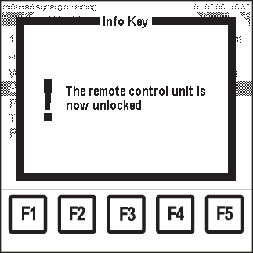
"Info Key - The remote control is now unlocked" screen
The "Info Key - The remote control is now unlocked" screen appears.
The last screen called up prior to locking appears. All menu items can now be accessed without restrictions.
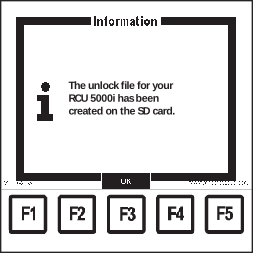
An Unlock function has been added to the RCU 5000i remote control unit from software version OFFICIAL RCU V1.14.12.
This Unlock function changes the "Locked" profile and enables access to the "Profile / Keys" screen in the machine pre-sets in order, for example, to add an Administrator key or modify the "Locked" profile.
More information about the Unlock function can be found in the "Machine pre-sets" chapter, "RCU 5000i - Unlock function" section.
MIG/MAG synergic welding relates to synergic mode on the power source. Once the wirefeed speed parameter is set, the welding current and sheet thickness parameters are adjusted accordingly.
The current welding amperage and sheet thickness values appear in the display area.
MIG/MAG synergic welding relates to synergic mode on the power source. Once the wirefeed speed parameter is set, the welding current and sheet thickness parameters are adjusted accordingly.
The current welding amperage and sheet thickness values appear in the display area.
Main menu: "MIG/MAG synergic welding" menu item selected
1Press the "Menu" button (1):- Main menu appears
2Select "MIG/MAG synergic welding" menu item using the adjusting dial (18)
3Press OK (3):- The last "Data" screen called up appears.
- Retrieving a welding program
- Setting working parameters
- Switching to extra-large display
- Setting process settings parameters
- Setting additional parameters: special 2-step, special 4-step, spot welding
- Setting SynchroPuls parameters
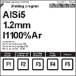
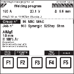
MIG/MAG synergic welding: "Welding program" screen
1Call up "MIG/MAG synergic welding" menu item
2Select "Welding program" screen by pressing the right arrow key (8)- "Welding program" screen appears
- Filler metal
- Wire diameter
- Shielding gas
- Reference number(s) for the stored welding program characteristic(s)
e.g.:
For AlSi5 with Ø 1.2 mm and shielding gas 100% Ar, there is a pulsed characteristic, a standard characteristic and a CMT characteristic
MIG/MAG synergic welding: "Welding program" screen
1Call up "MIG/MAG synergic welding" menu item
2Select "Welding program" screen by pressing the right arrow key (8)- "Welding program" screen appears
- Filler metal
- Wire diameter
- Shielding gas
- Reference number(s) for the stored welding program characteristic(s)
e.g.:
For AlSi5 with Ø 1.2 mm and shielding gas 100% Ar, there is a pulsed characteristic, a standard characteristic and a CMT characteristic
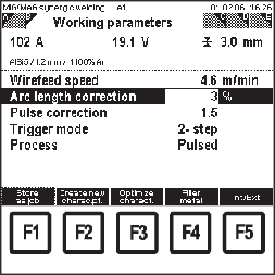
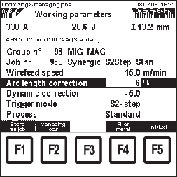
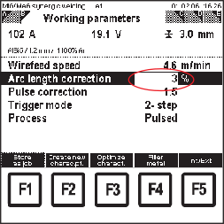
MIG/MAG synergic welding: "Working parameters" screen, arc length correction selected
1Call up "MIG/MAG synergic welding" menu item
2Select "Working parameters" screen by pressing the right arrow key (8):- "Working parameters" screen appears.
3Select the corresponding working parameters using down (6) or up (7) keys
4Use the adjusting dial (18) to alter the parameter value- A parameter value can only be altered within the defined setting range. The setting range is highlighted.
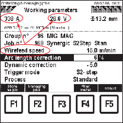
The welding amperage, welding voltage and sheet thickness values appear in the display area. If the "wirefeed speed" parameter is altered, the values in the display area also change accordingly.
MIG/MAG synergic welding: "Working parameters" screen, arc length correction selected
1Call up "MIG/MAG synergic welding" menu item
2Select "Working parameters" screen by pressing the right arrow key (8):- "Working parameters" screen appears.
3Select the corresponding working parameters using down (6) or up (7) keys
4Use the adjusting dial (18) to alter the parameter value- A parameter value can only be altered within the defined setting range. The setting range is highlighted.
The welding amperage, welding voltage and sheet thickness values appear in the display area. If the "wirefeed speed" parameter is altered, the values in the display area also change accordingly.
The following trigger modes can be set:- 2-step
- Special 2-step
- 4-step
- Special 4-step
- Spot welding
- Pulse (MIG/MAG pulse synergic welding)
- Standard (MIG/MAG standard synergic welding)
- CMT (Cold Metal Transfer)
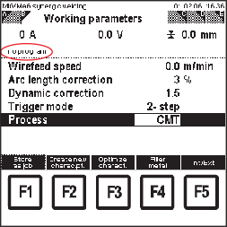
MIG/MAG synergic welding: "Working parameters" screen, "no program" for "CMT" process
If the set welding program and the selected process do not correspond, or if there is no welding program for the selected process, "no program" appears in the display area.
The "Wirefeed speed" parameter cannot be altered.
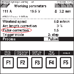
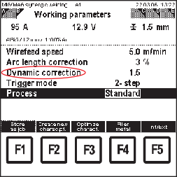
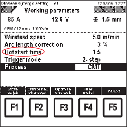
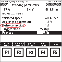
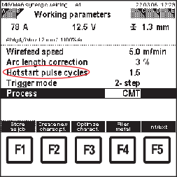
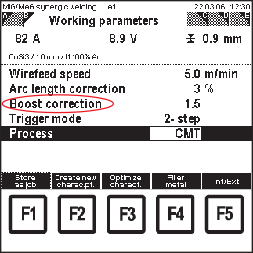
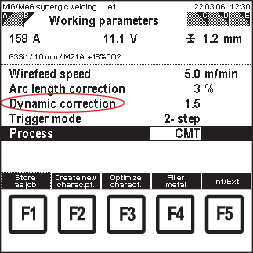
Individual parameters are displayed differently depending on the selected process and welding program:
Process | Parameter |
|---|
Pulse | Pulse correction |
Standard | Dynamic correction |
in the CMT process | HotStart time
Pulse correction
HotStart pulse cycles
Boost correction
Dynamic correction |
"Pulse correction" parameter in the pulse process
"Dynamic correction" parameter in the standard process
"Hotstart time" parameter for the CMT process
"Pulse correction" parameter for the CMT process
"Hotstart pulse cycles" parameter for the CMT process
"Boost correction" parameter for the CMT process
"Dynamic correction" parameter for the CMT process
- CMT power source (e.g. TPS 4000 CMT)
- CMT wirefeeder (e.g. VR 7000 CMT)
- CMT drive unit with wire buffer (e.g. Robacta Drive CMT)
- CMT interconnecting hosepack
The M0842 welding database is required for the CMT Advanced process.
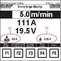
The wirefeed speed, welding current and welding voltage parameters can be displayed in extra-large format. The wire feed unit and push-pull unit motor current is also shown in the "Extra-large display" screen as an actual value.
The wirefeed speed, welding current and welding voltage parameters can be displayed in extra-large format. The wire feed unit and push-pull unit motor current is also shown in the "Extra-large display" screen as an actual value.
MIG/MAG synergic welding: "Extra-large display" screen
1Call up "MIG/MAG synergic welding" menu item
2Select "Extra-large display" screen by pressing the right arrow key (8):- "Extra-large display" screen appears
- The value for wire feed speed can be altered in the "Extra-large display" screen using the adjusting dial (18).
If the "Wirefeed speed" parameter is altered, the values for welding current and welding voltage also change accordingly.
| (1) | Wire-feed unit motor current |
| (2) | Push-pull unit motor current |
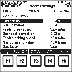
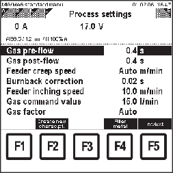
MIG/MAG synergic welding: "Process settings" screen, gas pre-flow selected
1Call up "MIG/MAG synergic welding" menu item
2Select "Process settings" screen by pressing the right arrow key (8).- "Process settings" screen appears
3Select the process settings parameters using the down (6) or up (7) keys
4Change the value of the process settings parameters using the adjusting dial (18)- The value of the process settings parameters can only be altered within the defined setting range. The setting range is highlighted.
MIG/MAG synergic welding: "Process settings" screen, gas pre-flow selected
1Call up "MIG/MAG synergic welding" menu item
2Select "Process settings" screen by pressing the right arrow key (8).- "Process settings" screen appears
3Select the process settings parameters using the down (6) or up (7) keys
4Change the value of the process settings parameters using the adjusting dial (18)- The value of the process settings parameters can only be altered within the defined setting range. The setting range is highlighted.
The following additional parameters can be set:- Starting current Is
- Starting-current dur. ts
- Slope 1 Sl1
- Slope 2 Sl2
- Final-current duration te
- Final current
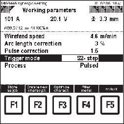
"Working parameters" screen: S2-step trigger mode
1Call up "MIG/MAG synergic welding" menu item
2Select "Working parameters" screen by pressing the right arrow key (8)- "Working parameters" screen appears
3Select the "trigger mode" parameter using the down (6) or up (7) keys
4Set to S2-step using adjusting dial (18)
5Select "Special 2-step" screen by pressing the right arrow key (8)- "Special 2-step" screen appears
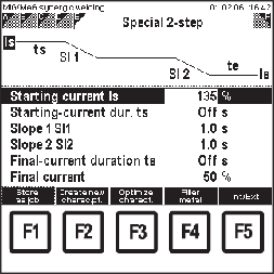
MIG/MAG synergic welding: "Special 2-step" screen, starting current Is selected
6Select further parameters using down (6) or up (7) keys
7Change the value of the further parameters using the adjusting dial (18)- The value of the further parameters can only be altered within the defined setting range. The setting range is highlighted.
The following additional parameters can be set:- Starting current Is
- Starting-current dur. ts
- Slope 1 Sl1
- Slope 2 Sl2
- Final-current duration te
- Final current
"Working parameters" screen: S2-step trigger mode
1Call up "MIG/MAG synergic welding" menu item
2Select "Working parameters" screen by pressing the right arrow key (8)- "Working parameters" screen appears
3Select the "trigger mode" parameter using the down (6) or up (7) keys
4Set to S2-step using adjusting dial (18)
5Select "Special 2-step" screen by pressing the right arrow key (8)- "Special 2-step" screen appears
MIG/MAG synergic welding: "Special 2-step" screen, starting current Is selected
6Select further parameters using down (6) or up (7) keys
7Change the value of the further parameters using the adjusting dial (18)- The value of the further parameters can only be altered within the defined setting range. The setting range is highlighted.
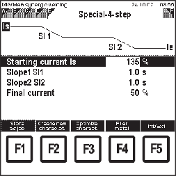
The following additional parameters can be set:- Starting current Is
- Slope 1 Sl1
- Final current
- Slope 2 Sl2
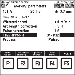
"Working parameters" screen: S4-step trigger mode
1Call up "MIG/MAG synergic welding" menu item
2Select "Working parameters" screen by pressing the right arrow key (8)- "Working parameters" screen appears
3Select the "trigger mode" parameter using the down (6) or up (7) keys
4Set to S4-step using adjusting dial (18)
5Select "Special 4-step" screen by pressing the right arrow key (8)- "Special 4-step" screen appears
MIG/MAG synergic welding: "Special 4-step" screen, starting current Is selected
6Select further parameters using down (6) or up (7) keys
7Change the value of further parameters using the adjusting dial (18)- The value of the further parameters can only be altered within the defined setting range. The setting range is highlighted.
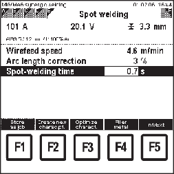
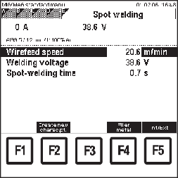
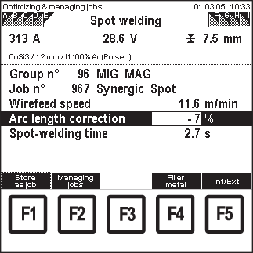
The following parameters can be set:- Wire feed speed
- Arc length correction
- Spot welding time
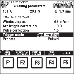
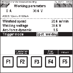
"Working parameters" screen: spot welding trigger mode
1Call up "MIG/MAG synergic welding" menu item
2Select "Working parameters" screen by pressing the right arrow key (8)- "Working parameters" screen appears
3Select the "trigger mode" parameter using the down (6) or up (7) keys
4Set spot welding using adjusting dial (18)
5Select "Spot welding" screen by pressing the right arrow key (8)- "Spot welding" screen appears
MIG/MAG synergic welding: "Spot welding" screen, wirefeed speed selected
6Select parameters using the down (6) or up (7) keys
7Change the value of the parameters using the adjusting dial (18)- The value of the parameters can only be altered within the defined setting range. The setting range is highlighted.
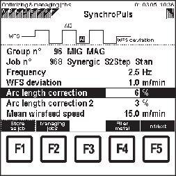
If the SynchroPuls software option is installed on the power source, the screen for the SynchroPuls parameters is also available. The screen is added to the clothesline.
If the SynchroPuls software option is installed on the power source, the screen for the SynchroPuls parameters is also available. The screen is added to the clothesline.
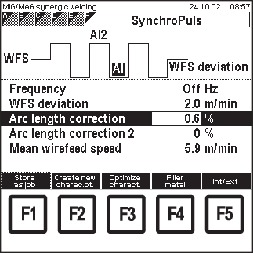
MIG/MAG synergic welding: "SynchroPuls" screen
1Call up "MIG/MAG synergic welding" menu item
2Select "SynchroPuls" screen by pressing the right arrow key (8).- "SynchroPuls" screen appears
3Select SynchroPuls parameters using down (6) or up (7) keys
4Change the values of the SynchroPuls parameters using the adjusting dial (18)- The value of the SynchroPuls parameters can only be altered within the defined setting range. The setting range is highlighted.
Unlike MIG/MAG synergic welding, in MIG/MAG manual welding the welding parameters are set individually.
Unlike MIG/MAG synergic welding, in MIG/MAG manual welding the welding parameters are set individually.
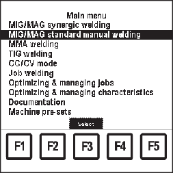
Main menu: "MIG/MAG standard manual welding" menu item selected
1Press the "Menu" button (1):- Main menu appears
2Select "MIG/MAG standard manual welding" menu item using the adjusting dial (18)
3Press OK (3):- The last "Data" screen called up appears.
- Retrieving a welding program
- Setting working parameters
- Switching to extra-large display
- Setting process settings parameters
- Setting additional spot welding parameters
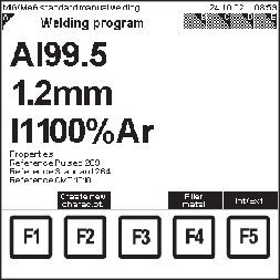
MIG/MAG standard manual welding: "Welding program" screen
1Call up "MIG/MAG standard manual welding" menu item
2Select "Welding program" screen by pressing the right arrow key (8)- "Welding program" screen appears
- Filler metal
- Wire diameter
- Shielding gas
- Reference number(s) for the stored welding program characteristic(s)
e.g.:
For AlSi5 with Ø 1.2 mm and shielding gas 100 % Ar, there is a pulsed characteristic, a standard characteristic and a CMT characteristic
MIG/MAG standard manual welding: "Welding program" screen
1Call up "MIG/MAG standard manual welding" menu item
2Select "Welding program" screen by pressing the right arrow key (8)- "Welding program" screen appears
- Filler metal
- Wire diameter
- Shielding gas
- Reference number(s) for the stored welding program characteristic(s)
e.g.:
For AlSi5 with Ø 1.2 mm and shielding gas 100 % Ar, there is a pulsed characteristic, a standard characteristic and a CMT characteristic
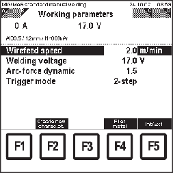
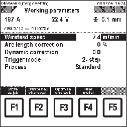
MIG/MAG standard manual welding: "Working parameters" screen, wire feed speed selected
1Call up "MIG/MAG standard manual welding" menu item
2Select "Working parameters" screen by pressing the right arrow key (8)- "Working parameters" screen appears
3Select the corresponding working parameters using down (6) or up (7) keys
4Use the adjusting dial (18) to alter the parameter value- The parameter value can only be altered within the defined setting range. The setting range is highlighted.
MIG/MAG standard manual welding: "Working parameters" screen, wire feed speed selected
1Call up "MIG/MAG standard manual welding" menu item
2Select "Working parameters" screen by pressing the right arrow key (8)- "Working parameters" screen appears
3Select the corresponding working parameters using down (6) or up (7) keys
4Use the adjusting dial (18) to alter the parameter value- The parameter value can only be altered within the defined setting range. The setting range is highlighted.
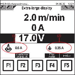
The wirefeed speed, welding current and welding voltage parameters can be displayed in extra-large format. The wire feed unit and push-pull unit motor current is also shown in the "Extra-large display" screen as an actual value.
The wirefeed speed, welding current and welding voltage parameters can be displayed in extra-large format. The wire feed unit and push-pull unit motor current is also shown in the "Extra-large display" screen as an actual value.
MIG/MAG standard manual welding: "Extra-large display" screen
1Call up "MIG/MAG standard manual welding" menu item
2Select "Extra-large display" screen by pressing the right arrow key (8)- "Extra-large display" screen appears
- The values for wire feed speed and welding voltage can be altered in the "Extra-large display" screen using the adjusting dial (18).
- Welding current is a display value:
- during welding
... actual value
- following welding
... hold value
| (1) | Wire-feed unit motor current |
| (2) | Push-pull unit motor current |
MIG/MAG standard manual welding: "Process settings" screen, gas pre-flow selected
1Call up "MIG/MAG standard manual welding" menu item
2Select "Process settings" screen by pressing the right arrow key (8)- "Process settings" screen appears
3Select the process settings parameters using the down (6) or up (7) keys
4Change the value of the process settings parameters using the adjusting dial (18).- The value of the process settings parameters can only be altered within the defined setting range. The setting range is highlighted.
MIG/MAG standard manual welding: "Process settings" screen, gas pre-flow selected
1Call up "MIG/MAG standard manual welding" menu item
2Select "Process settings" screen by pressing the right arrow key (8)- "Process settings" screen appears
3Select the process settings parameters using the down (6) or up (7) keys
4Change the value of the process settings parameters using the adjusting dial (18).- The value of the process settings parameters can only be altered within the defined setting range. The setting range is highlighted.
The following parameters can be set:- Wire feed speed
- Arc length correction
- Spot welding time
"Working parameters" screen: spot welding trigger mode
1Call up "MIG/MAG standard manual welding" menu item
2Select "Working parameters" screen by pressing the right arrow key (8)- "Working parameters" screen appears
3Select the "trigger mode" parameter using the down (6) or up (7) keys
4Set spot welding using adjusting dial (18)
5Select "Spot welding" screen by pressing the right arrow key (8)- "Spot welding" screen appears
MIG/MAG synergic welding: "Spot welding" screen, wirefeed speed selected
6Select parameters using the down (6) or up (7) keys
7Change the value of the parameters using the adjusting dial (18)- The value of the parameters can only be altered within the defined setting range. The setting range is highlighted.
The following parameters can be set:- Wire feed speed
- Arc length correction
- Spot welding time
"Working parameters" screen: spot welding trigger mode
1Call up "MIG/MAG standard manual welding" menu item
2Select "Working parameters" screen by pressing the right arrow key (8)- "Working parameters" screen appears
3Select the "trigger mode" parameter using the down (6) or up (7) keys
4Set spot welding using adjusting dial (18)
5Select "Spot welding" screen by pressing the right arrow key (8)- "Spot welding" screen appears
MIG/MAG synergic welding: "Spot welding" screen, wirefeed speed selected
6Select parameters using the down (6) or up (7) keys
7Change the value of the parameters using the adjusting dial (18)- The value of the parameters can only be altered within the defined setting range. The setting range is highlighted.
- MIG/MAG synergic welding
- MIG/MAG standard manual welding
- Optimising & managing jobs (only for saved MIG/MAG jobs)
- MIG/MAG synergic welding
- MIG/MAG standard manual welding
- Optimising & managing jobs (only for saved MIG/MAG jobs)
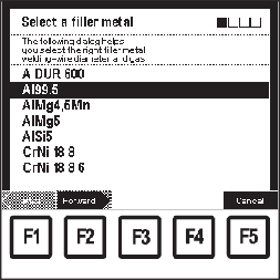
"Select a filler metal" screen: Al99.5 selected
1In the relevant "Data" screen, press F4 "Filler metal"- The 1st screen in the wizard appears ("Select a filler metal")
2Select required filler metal using the adjusting dial (18)
3Press F2 "Forward":- The 2nd screen in the wizard appears ("Select a wire diameter")
- Only the wire diameters available for the filler metal selected in the 1st screen are shown.
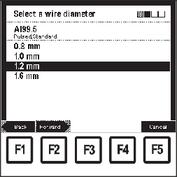
"Select a wire diameter" screen: 1.2 mm selected
4Select corresponding wire diameter using the adjusting dial (18)
5Press F2 "Forward":- The 3rd screen in the wizard appears ("Select a shielding gas")
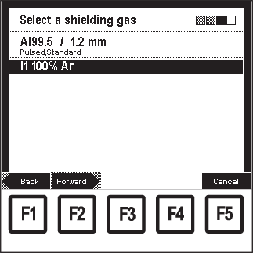
- Only the gases available for the filler metal selected in the 1st screen and wire diameter selected in the 2nd screen are shown.
"Select a shielding gas" screen: I1 100% Ar selected
6Select corresponding gas using the adjusting dial (18)
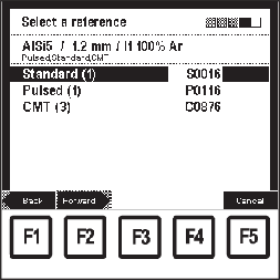
7Press F2 "Forward":- The "Select a reference" screen only appears if there are several characteristics for the selected filler metal, wire diameter and shielding gas.
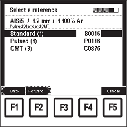
- The value given in brackets after the process indicates how many characteristics there are for this process.
Example: AlSi 5 / 1.2 mm / I1 100% Ar screen "Select a reference": Characteristic S0016 selected
8Select the corresponding process using the down (6) or up (7) keys
9Select the corresponding characteristic reference number using the adjusting dial (18)- E.g.:
Characteristic C0876 is only suitable for CMT.
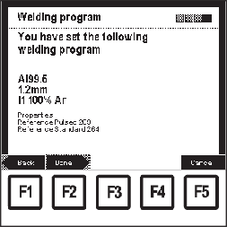
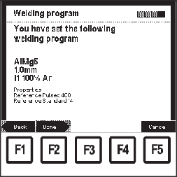
10Press F2 "Forward"- The last screen in the wizard ("Welding program") is shown as a confirmation
- By pressing F1 "Back", the screens of the steps already performed can be displayed again. Changes can be made.
"Welding program" screen: Confirmation
11Press F2 "Done"- The set welding program is accepted, the last "Data" screen displayed appears
"Creating new user characteristics - Optimize characteristics" can only be carried out in the MIG/MAG synergic welding menu item.
"Creating new user characteristics - Optimize characteristics" can only be carried out in the MIG/MAG synergic welding menu item.
Every welding program is based on a welding characteristic. The characteristics of selected welding programs can be altered to suit a specific user. These alterations are stored in so-called user characteristics.
The programming of a user characteristic is necessary- if filler metals (shielding gas, welding wire diameter) not contained in the welding database are used.
- for optimising the welding process (e.g.: increasing welding speed, changing the weld penetration ratios, changing the weld appearance).
NOTE!
Reprogramming a characteristic requires a knowledge of arc and welding technology.
- Select similar characteristic
- Determine the power range of the user characteristic
- If necessary, complete the user characteristic by plotting additional characteristic points
Important basic settings are transferred into the new characteristic using this procedure.
NOTE!
At least two characteristic points are needed to create a user characteristic.
To optimise all power ranges, however, 6-10 characteristic points should be programmed (one point per material strength). A maximum of 19 characteristic points can be programmed.
1In each "Data" screen, set a similar welding program or the welding program to be changed
2Press F3 "Optimize characteristic":
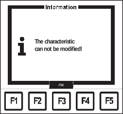
Information screen - "Characteristics cannot be modified!"
If it is not possible to edit a characteristic, the message "Characteristic cannot be modified" is displayed.
The first The 1st screen in the wizard appears ("Optimize characteristics")
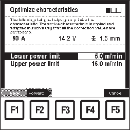
"Optimize characteristic" screen: setting power values
3Select the lower and upper power limits using down (6) or up (7) keys
4Set lower and upper power limit using the adjusting dial (18)- The parameter value can only be altered within the defined setting range. The setting range is highlighted.
- The values displayed in the display area for current, voltage and sheet thickness depend directly on the power values entered.
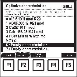
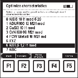
"Optimize characteristic" screen: Selecting the synergic line
5Press F2 "Forward":- The 2nd screen in the wizard appears ("Optimize characteristic")
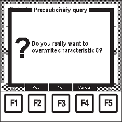
6Select corresponding characteristic using the adjusting dial (18)- If an existing characteristic is to be overwritten, a precautionary query appears.
Precautionary query for overwriting the characteristic
7Press F3 "Name characteristic" to name the characteristic:- "Name characteristic" screen appears
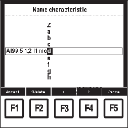
"Name characteristic" screen
8Select corresponding characters using the adjusting dial (18)
9Press F4 ">" to enter the next character- Corrections can be carried out using F3 "<" or F2 "< Delete"
10Press F1 "Accept" when finished:- The new name is accepted, "Optimize characteristics" screen appears
"Optimize characteristic" screen: Selecting the synergic line
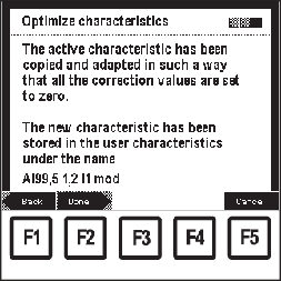
11Press F2 "Forward":- The 3rd screen in the wizard appears as confirmation ("Optimize characteristic")
- By pressing F1 "Back", the screens of the steps already performed can be displayed again. Changes can be made.
"Optimize characteristic" wizard: confirmation of optimised characteristic
12Press F2 "Done":- The last "Data" screen displayed appears.
- MIG/MAG synergic welding
- MIG/MAG standard manual welding
- MIG/MAG synergic welding
- MIG/MAG standard manual welding
Various parameter settings can be saved in the user characteristics as characteristic points.
The following are required to create a new characteristic point:- Welding program (filler metal, wire diameter, shielding gas), for which a characteristic point is to be created
- Value for the wirefeed speed (e.g. reference values corresponding to previous welding attempts, past experience or material strength)
NOTE!
Creating new characteristic points requires a knowledge of arc and welding technology.
NOTE!
At least two characteristic points are needed to create a user characteristic.
To optimise all power ranges, however, 6-10 characteristic points should be programmed (one point per material strength). A maximum of 19 characteristic points can be programmed.
Procedure for when certain parameter settings are to be saved as a characteristic point:
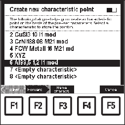
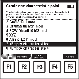
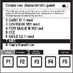
"Create new characteristic point" screen: No.6 - "Al99.5 1.2 I1 mod selected"
1Call up the welding program for which a characteristic point is to be created
2Set the wirefeed speed for which the characteristic point is to be created
3In the relevant "Data" screen, press F2 "Create new characteristic point"- The 1st screen in the wizard appears ("Create new characteristic point")
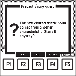
4Select corresponding characteristic using the adjusting dial (18)- If the characteristic point to be created is to be added to a characteristic that does not correspond to the currently set characteristic (e.g. adding an aluminium characteristic point to a CuSi characteristic), a precautionary query appears
Precautionary query: characteristic point does not match
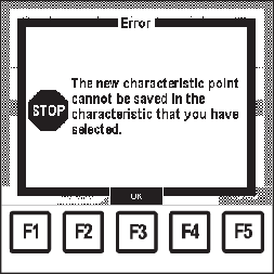
5Press F2 "Yes" or F3 "No" or F4 "Cancel"- If a standard characteristic point is to be added to a pulse characteristic or vice versa, an error message appears.
Error message: characteristic point cannot be saved
6Press F3 "OK"- The 1st screen in the wizard appears ("Create new characteristic point")
"Create new characteristic point" screen: No. 7 - < Empty characteristic > selected
7Select another characteristic using the adjusting dial (18)
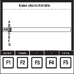
8Press F3 "Name characteristic" to name the characteristic:- "Name characteristic" screen appears
"Name characteristic" screen
9Select corresponding characters using the adjusting dial (18)
10Press F4 ">" to enter the next character- Corrections can be carried out using F3 "<" or F2 "< Delete".
11Press F1 "Accept" when finished:- The new name is accepted, "Create new characteristic point" screen appears
"Create new characteristic point" screen
12Press F2 "Forward":- The 2nd screen in the wizard appears as confirmation ("Create new characteristic point")
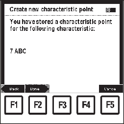
"Create new characteristic point" screen: confirmation of the saved characteristic point
13Press F2 "Done": - The characteristic point is saved, the corresponding "Data" screen appears.
- By pressing F1 "Back", the screens of the steps already performed can be displayed again. Changes can be made.
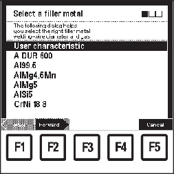
"Select a filler metal" screen: User characteristic selected
1In the corresponding "Data" screen, press F4 "Filler metal": - The 1st screen in the wizard appears ("Select a filler metal")
2Select "User characteristic" using the adjusting dial (18)
3Press F2 "Forward":- The 2nd screen in the wizard appears ("Select a user characteristic")
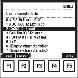
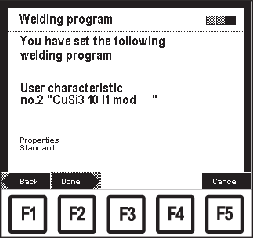
"Select a user characteristic" screen: no.2 "CuSi3 10 I1 mod" selected
4Select corresponding user characteristic using the adjusting dial (18)
5Press F2 "Forward":- The 3rd screen in the wizard ("Welding program") is shown as a confirmation
- By pressing F1 "Back", the screens of the steps already performed can be displayed again. Changes can be made.
"Welding program" screen: confirmation of user characteristic
6Press F2 "Done":- The set user characteristic is accepted, the last "Data" screen displayed appears
"Select a filler metal" screen: User characteristic selected
1In the corresponding "Data" screen, press F4 "Filler metal": - The 1st screen in the wizard appears ("Select a filler metal")
2Select "User characteristic" using the adjusting dial (18)
3Press F2 "Forward":- The 2nd screen in the wizard appears ("Select a user characteristic")
"Select a user characteristic" screen: no.2 "CuSi3 10 I1 mod" selected
4Select corresponding user characteristic using the adjusting dial (18)
5Press F2 "Forward":- The 3rd screen in the wizard ("Welding program") is shown as a confirmation
- By pressing F1 "Back", the screens of the steps already performed can be displayed again. Changes can be made.
"Welding program" screen: confirmation of user characteristic
6Press F2 "Done":- The set user characteristic is accepted, the last "Data" screen displayed appears
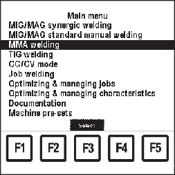
Main menu: "Rod electrode (MMA) welding" menu item selected
1Press the "Menu" button (1)- Main menu appears
2Select "Rod electrode (MMA) welding" menu item using the adjusting dial (18)
3Press OK (3)- The last "Data" screen called up appears
Main menu: "Rod electrode (MMA) welding" menu item selected
1Press the "Menu" button (1)- Main menu appears
2Select "Rod electrode (MMA) welding" menu item using the adjusting dial (18)
3Press OK (3)- The last "Data" screen called up appears
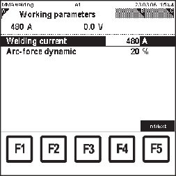
Rod electrode (MMA) welding: "Working parameters" screen, welding current selected
1Call up "Rod electrode (MMA) welding" menu item
2Select "Working parameters" screen by pressing the right arrow key (8)- "Working parameters" screen appears.
3Select the corresponding working parameters using down (6) or up (7) keys
4Use the adjusting dial (18) to alter the parameter value- The parameter value can only be altered within the defined setting range. The setting range is highlighted.
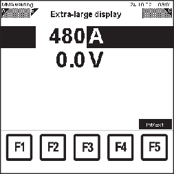
The welding current and welding voltage parameters can be displayed in extra-large format:
Rod electrode (MMA) welding: "Extra-large display" screen
1Call up "Rod electrode (MMA) welding" menu item
2Select "Extra-large display" screen by pressing the right arrow key (8)- "Extra-large display" screen appears
- The value for the welding amperage can be altered in the "Extra-large display" screen by using the adjusting dial (18).
- Welding voltage is a display value:
- during welding
... actual value
- following welding
... hold value
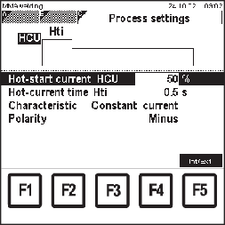
Rod electrode (MMA) welding: "Process settings" screen, hotstart current HCU selected
1Call up "Rod electrode (MMA) welding" menu item
2Select "Process settings" screen by pressing the right arrow key (8).- "Process settings" screen appears
3Select the process settings parameters using the down (6) or up (7) keys
4Change the value of the process setting using the adjusting dial (18)- The value of the process settings parameters can only be altered within the defined setting range. The setting range is highlighted.
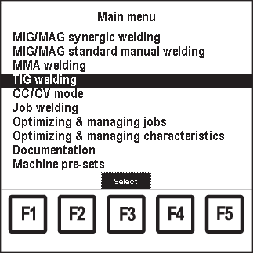
Main menu: "TIG welding" menu item selected
1Press the "Menu" button (1)- Main menu appears
2Select "TIG welding" menu item using the adjusting dial (18)
3Press OK (3)- The last "Data" screen called up appears
Main menu: "TIG welding" menu item selected
1Press the "Menu" button (1)- Main menu appears
2Select "TIG welding" menu item using the adjusting dial (18)
3Press OK (3)- The last "Data" screen called up appears
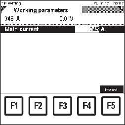
TIG welding: "Working parameters" screen, main current selected
1Call up "TIG welding" menu item
2Select "Working parameters" screen by pressing the right arrow key (8)- "Working parameters" screen appears.
3Select the corresponding working parameters using down (6) or up (7) keys
4Use the adjusting dial (18) to alter the parameter value- The parameter value can only be altered within the defined setting range. The setting range is highlighted.
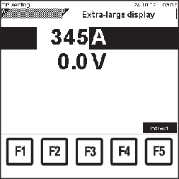
The welding current and welding voltage parameters can be displayed in extra-large format:
TIG welding: "Extra-large display" screen
1Call up "TIG welding" menu item
2Select "Extra-large display" screen by pressing the right arrow key (8)- "Extra-large display" screen appears
- The value for the welding amperage can be altered in the "Extra-large display" screen by using the adjusting dial (18).
- Welding voltage is a display value:
- during welding
... actual value
- following welding
... hold value
If the "CC/CV mode" software option is installed on the power source, the "CC/CV mode" menu item appears in the main menu.
The CC/CV mode menu item allows the user to operate the power source with either constant welding voltage or constant welding current.
Parameter changes in the "CC/CV mode" menu item can be made via a robot control or the RCU 5000i remote control.
"CC/CV mode" is used in hot wire applications, for example.
If the "CC/CV mode" software option is installed on the power source, the "CC/CV mode" menu item appears in the main menu.
The CC/CV mode menu item allows the user to operate the power source with either constant welding voltage or constant welding current.
Parameter changes in the "CC/CV mode" menu item can be made via a robot control or the RCU 5000i remote control.
"CC/CV mode" is used in hot wire applications, for example.
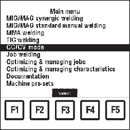
Main menu: "CC/CV mode" menu item selected
1Press the "Menu" button (1)- Main menu appears
2Select "CC/CV mode" menu item using the adjusting dial (18)
3Press OK (3)- The last "Data" screen called up appears
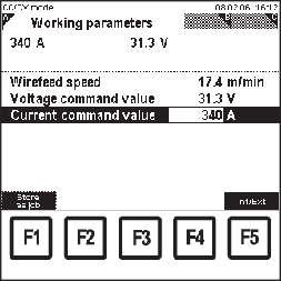
CC/CV mode: "Working parameters" screen, current command value selected
1Call up "CC/CV mode"
2Select "Working parameters" screen by pressing the right arrow key (8)- "Working parameters" screen appears.
3Select the corresponding working parameters using down (6) or up (7) keys
4Use the adjusting dial (18) to alter the parameter value- The parameter value can only be altered within the defined setting range. The setting range is highlighted.
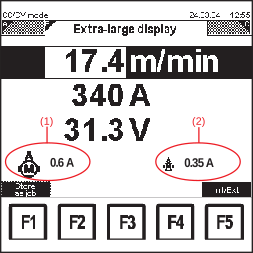
The wirefeed speed, voltage command value and current command value parameters can be displayed in extra-large format:
CC/CV mode: "Extra-large display" screen
1Call up "CC/CV mode"
2Select "Extra-large display" screen by pressing the right arrow key (8)- "Extra-large display" screen appears
- The values for wirefeed speed, voltage command value and current command value can be altered in the "Extra-large display" screen using the adjusting dial (18).
- Welding voltage is a display value:
- during welding
... actual value
- following welding
... hold value
| (1) | Wire-feed unit motor current |
| (2) | Push-pull unit motor current |
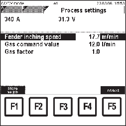
CC/CV mode: "Process settings" screen
1Call up "CC/CV mode"
2Select "Process settings" screen by pressing the right arrow key (8).- "Process settings" screen appears
3Use the adjusting dial (18) to alter the parameter value- The parameter value can only be altered within the defined setting range. The setting range is highlighted.
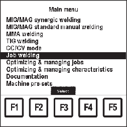
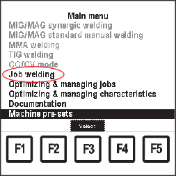
Main menu: "Job welding" menu item selected
1Press the "Menu" button (1)- Main menu appears
2Select "Job welding" menu item using the adjusting dial (18)
3Press OK (3)- The last "Data" screen called up appears
Main menu: "Job welding" menu item selected
1Press the "Menu" button (1)- Main menu appears
2Select "Job welding" menu item using the adjusting dial (18)
3Press OK (3)- The last "Data" screen called up appears
- Actual power correction
- actual arc-length correction
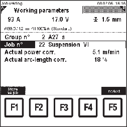
Job welding: "Working parameters" screen, actual power correction for job no. 22 from group 2 selected (example for a MIG/MAG job)
1Call up the "Job welding" menu item
2Select "Working parameters" screen by pressing the right arrow key (8)- "Working parameters" screen appears.
3Select "group no." parameter using the down (6) or up (7) keys
4Select desired group (0 - 99) using the adjusting dial (18)
5Select "Job n°" parameter using the down (6) or up (7) keys
6Select desired job (0 - 999) using the adjusting dial (18) - If a job is selected from the next group, the group displayed also changes accordingly.
7Select the corresponding working parameters using down (6) or up (7) keys
8Use the adjusting dial (18) to alter the parameter value- The parameter value can only be altered within the defined setting range. The setting range is highlighted.
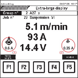
For a selected job, the wirefeed speed, welding current and welding voltage parameters can be displayed in extra-large format.
Job welding: "Extra-large display" screen
1Call up the "Job welding" menu item
2Select "Extra-large display" screen by pressing the right arrow key (8)- "Extra-large display" screen appears
- The parameters "group no." and "job no." can be selected using the down (6) or up (7) keys, and altered using the adjusting dial (18).
- The wirefeed speed can be adjusted within the defined correction boundaries for the job selected using the adjusting dial (18).
- Welding current and welding voltage are purely display values
| (1) | Wire-feed unit motor current |
| (2) | Push-pull unit motor current |
NOTE!
Neither the welding process nor the currently selected characteristic can be changed during CMT Advanced welding.
To change the welding process or characteristic:
- first, end the CMT Advanced process
- wait 300 - 600 ms
Another welding process or characteristic cannot be selected during this time.
- Resume the welding process with another welding process or characteristic.
- MIG/MAG synergic welding
- CC/CV mode
- Job welding
- Optimizing & managing jobs
- MIG/MAG synergic welding
- CC/CV mode
- Job welding
- Optimizing & managing jobs
1Set all parameters in all screens displayed- Set parameters in screen A
- Set parameters in screen B
- Set parameters in Screen C, etc.
2Press F1 "Store as job" and follow the menu
Procedure for when certain parameter settings are to be stored as a job:
"Store as job - Group" screen: no. 6 <Empty group> selected
1In the corresponding "Data" screen, press F1 "Store as job" - The 1st screen in the wizard appears ("Store as job - Group")
2Select corresponding group using the adjusting dial (18)
3Press F3 "Name group" to name the group:- "Name group" screen appears
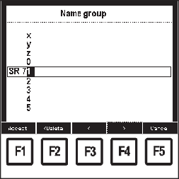
"Name group" screen
4Select corresponding characters using the adjusting dial (18)
5Press F4 ">" to enter the next character- Corrections can be carried out by pressing F3 "<" or F2 "< Delete".
6Press F1 "Accept" when finished:- The new name is accepted, "Store as job - Group" screen appears
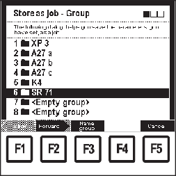
"Store as job - Group" screen: no. 6 SR 71 selected
7Press F2 "Forward":- The 2nd screen in the wizard appears ("Store as job - Memory location")
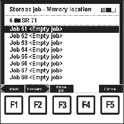
"Store as job - Memory location" screen: Job 61 <Empty job> selected
8Select corresponding job using the adjusting dial (18)
9Press F3 "Name job" to name the job:- "Name job" screen appears
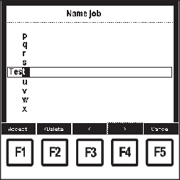
"Name job" screen
10Select corresponding characters using the adjusting dial (18)
11Press F4 ">" to enter the next character- Corrections can be carried out by pressing F3 "<" or F2 "< Delete".
12Press F1 "Accept" when finished:- The new name is accepted, "Store as job - Memory location" screen appears
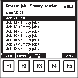
"Store as job - Memory location" screen: Job 61 Test selected
13Press F2 "Forward":- The 3rd screen in the wizard appears as confirmation ("Store as job").
- By pressing F1 "Back", the screens of the steps already performed can be displayed again. Changes can be made.
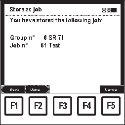
"Store as job" screen as confirmation
14Press F2 "Done":- The last selected "Data" screen appears.
- internally on the remote control
- externally, e.g. on the wire-feed unit, power source, other remote controls, robot control, etc.
If the system has an external operating facility, the relevant parameters are automatically set to external parameter entry, e.g.:
in the case of a connected wire-feed unit, the value for the "Wirefeed speed" parameter must be set on the wire-feed unit. If the parameter value is to be set on the RCU 5000i remote control unit, the "wirefeed speed" parameter must be converted to internal parameter entry.
The user can switch between internal and external parameter entry in the following menu items: |
- MIG/MAG synergic welding | - CC/CV mode |
- MIG/MAG standard manual welding | - Job welding |
- MMA welding | - Optimizing & managing jobs |
- TIG welding | |
- internally on the remote control
- externally, e.g. on the wire-feed unit, power source, other remote controls, robot control, etc.
If the system has an external operating facility, the relevant parameters are automatically set to external parameter entry, e.g.:
in the case of a connected wire-feed unit, the value for the "Wirefeed speed" parameter must be set on the wire-feed unit. If the parameter value is to be set on the RCU 5000i remote control unit, the "wirefeed speed" parameter must be converted to internal parameter entry.
The user can switch between internal and external parameter entry in the following menu items: |
- MIG/MAG synergic welding | - CC/CV mode |
- MIG/MAG standard manual welding | - Job welding |
- MMA welding | - Optimizing & managing jobs |
- TIG welding | |
1In the corresponding "Data" screen, press F5 "Int/Ext"- The remote control unit converts to the desired parameter entry:
Internal parameter entry (Int): | External parameter entry (Ext): |
|---|
The parameters to be set are entered and altered on the RCU 5000i remote control unit.
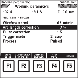
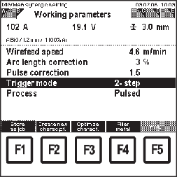
The selected parameter is shown with a black bar with a "window" for the parameter value. The parameter value in the "window" can be changed. | The parameters to be set are entered and altered at the power source, wirefeeder or via a robot control.
The selected parameter is shown with a continuous black bar on the remote control unit display. With external parameter entry, the parameter value cannot be altered on the remote control unit. |
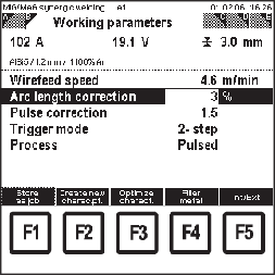
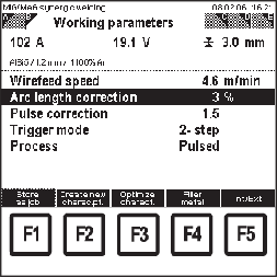
Example of internal parameter entry: black bar with "window" - Arc length correction selected | Example of external parameter entry: continuous black bar - Arc length correction selected |
NOTE!
The F5 "Int/Ext" function key is only active when a remote control is connected.
If the remote control is not connected, the F5 "Int/Ext" function key is greyed out:
Example of an unconnected remote control unit: F5 "Int/Ext" greyed out
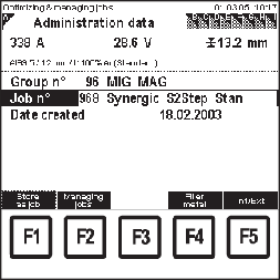
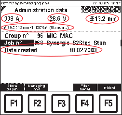
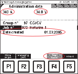
- Retrieving administration data
- Setting working parameters
- Setting job-specific parameters
Depending on the type of the selected job, many different screens are displayed on the "clothesline".
The sequence of displayed screens also depends on the type of job.
The following screens are shown in the case of MIG/MAG synergic jobs: |
- Administration data | - SynchroPuls 1) |
- Welding program | - Q-Master values |
- Working parameters | - Special 2-step 2) |
- Process settings | - Special-4-step 3) |
- Correction boundaries | - Spot welding 4) |
- Job-specific doc. | |
1) | Only displayed if the SynchroPulse option is installed on the power source |
2) | Only displayed if the trigger mode is set to S2-step for the selected job |
3) | Only displayed if the trigger mode is set to S4-step for the selected job |
4) | Only displayed if the trigger mode is set to spot welding for the selected job |
- Retrieving administration data
- Setting working parameters
- Setting job-specific parameters
Depending on the type of the selected job, many different screens are displayed on the "clothesline".
The sequence of displayed screens also depends on the type of job.
The following screens are shown in the case of MIG/MAG synergic jobs: |
- Administration data | - SynchroPuls 1) |
- Welding program | - Q-Master values |
- Working parameters | - Special 2-step 2) |
- Process settings | - Special-4-step 3) |
- Correction boundaries | - Spot welding 4) |
- Job-specific doc. | |
1) | Only displayed if the SynchroPulse option is installed on the power source |
2) | Only displayed if the trigger mode is set to S2-step for the selected job |
3) | Only displayed if the trigger mode is set to S4-step for the selected job |
4) | Only displayed if the trigger mode is set to spot welding for the selected job |
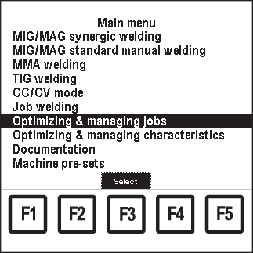
Main menu: "Optimizing & managing jobs" menu item selected
1Press the "Menu" button (1)- Main menu appears
2Select "Optimizing & managing jobs" menu item using the adjusting dial (18)
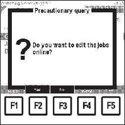
3Press OK (3)- Precautionary query "Do you want to edit the jobs online?" appears
Precautionary query: Do you want to edit the jobs online?
4Press F2 "Yes" or F3 "No"- Online editing - F2 "Yes"
The power source changes to the job correction menu, independent of the current power source settings. Data changed on the remote control unit also appear on the power source.
- Online editing - F3 "No"
Current power source settings remain unaffected. Data changed on the remote control unit appear only on the remote control unit.
- The last "Data" screen called up appears
- Managing jobs
- Retrieving administration data for a selected job
- Retrieving and changing a welding program for a selected job
- Retrieving and changing working parameters for a selected job
- Retrieving and changing process settings for a selected job
- Retrieving and changing special 2-step parameters for a selected job
- Retrieving and changing special 4-step parameters for a selected job
- Retrieving and changing spot welding parameters for a selected job
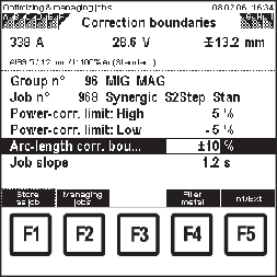
- Establishing correction boundaries for a selected job
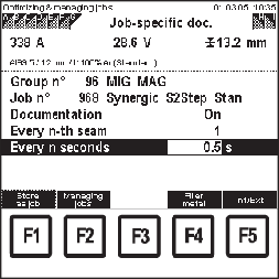
- Job-specific documentation
- Retrieving and changing SynchroPuls parameters for a selected job
- Establishing QMaster values for a selected job
- Creating a new characteristic point
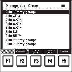
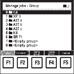
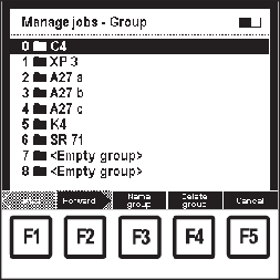
Optimizing and managing jobs: "Manage jobs - Group" screen
1Call up the "Optimizing & managing jobs" menu item
2Whatever screen is showing, press F1 "Manage jobs":- The 1st screen in the wizard appears ("Manage jobs - Group")
3Select desired group (0 - 99) using the adjusting dial (18)
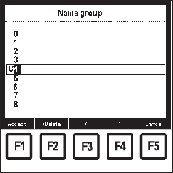
4Press F3 "Name group" to name a group- "Name group" screen appears
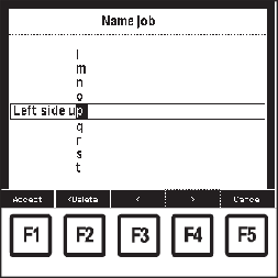
"Name group" screen
5Select corresponding characters using the adjusting dial (18)
6Press F4 ">" to enter the next character- Corrections can be carried out by pressing F3 "<" or F2 "< Delete".
7Press F1 "Accept" when finished:- The new name is accepted, "Manage jobs - Group" screen appears
Optimizing and managing jobs: "Manage jobs - Group" screen
8Press F2 "Forward":- The 2nd screen in the wizard appears ("Manage jobs - Memory location")
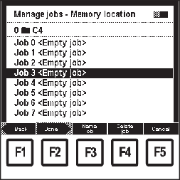
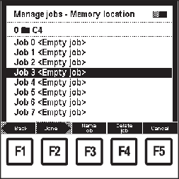
"Manage jobs - Memory location" screen
9Select desired memory location using the adjusting dial (18)
10Press F3 "Name job" to name the job:- "Name job" screen appears
"Name job" screen
11Select corresponding characters using the adjusting dial (18)
12Press F4 ">" to enter the next character- Corrections can be carried out by pressing F3 "<" or F2 "< Delete".
13Press F1 "Accept" when finished:- The new name is accepted, "Store as job - Memory location" screen appears
- By pressing F1 "Back", the screens of the steps already performed can be displayed again. Changes can be made.
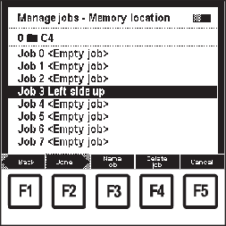
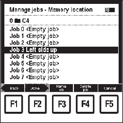
"Store as job - Memory location" screen: Job 3 Left side up selected
14Press F2 "Done":- The last selected "Data" screen appears.
Optimizing and managing jobs: "Manage jobs - Group" screen
1Call up the "Optimizing & managing jobs" menu item
2Whatever screen is showing, press F1 "Manage jobs":- The 1st screen in the wizard appears ("Manage jobs - Group")
3Select desired group (0 - 99) using the adjusting dial (18)
4Press F3 "Name group" to name a group- "Name group" screen appears
"Name group" screen
5Select corresponding characters using the adjusting dial (18)
6Press F4 ">" to enter the next character- Corrections can be carried out by pressing F3 "<" or F2 "< Delete".
7Press F1 "Accept" when finished:- The new name is accepted, "Manage jobs - Group" screen appears
Optimizing and managing jobs: "Manage jobs - Group" screen
8Press F2 "Forward":- The 2nd screen in the wizard appears ("Manage jobs - Memory location")
"Manage jobs - Memory location" screen
9Select desired memory location using the adjusting dial (18)
10Press F3 "Name job" to name the job:- "Name job" screen appears
"Name job" screen
11Select corresponding characters using the adjusting dial (18)
12Press F4 ">" to enter the next character- Corrections can be carried out by pressing F3 "<" or F2 "< Delete".
13Press F1 "Accept" when finished:- The new name is accepted, "Store as job - Memory location" screen appears
- By pressing F1 "Back", the screens of the steps already performed can be displayed again. Changes can be made.
"Store as job - Memory location" screen: Job 3 Left side up selected
14Press F2 "Done":- The last selected "Data" screen appears.
Optimizing and managing jobs: "Manage jobs - Group" screen
1Call up the "Optimizing & managing jobs" menu item
2Whatever screen is showing, press F1 "Manage jobs":- The 1st screen in the wizard appears ("Manage jobs - Group")
3When deleting groups, select groups to be deleted (0 - 99) using the adjusting dial (18)
4Press F4 "Delete group"- Precautionary query "Do you really want to delete the complete group 0?" appears
NOTE!
When deleting a group, all the jobs in that group are also deleted.
"Delete group" precautionary query
5Press F2 "Yes"- The selected group is deleted, the 1st screen in the wizard appears ("Manage jobs - Group")
"Manage jobs - Group" screen with deleted group
6Press F2 "Forward":- The 2nd screen in the wizard appears ("Manage jobs - Memory location")
"Manage jobs - Memory location" screen
7When deleting jobs, select relevant memory location using adjusting dial (18)
8Press F4 "Delete job":- Precautionary query "Do you really want to delete job 3?" appears
"Delete job" precautionary query
9Press F2 "Yes"- The selected job is deleted, the 2nd screen in the wizard appears ("Manage jobs - Memory location")
"Manage jobs - Memory location" screen
10Press F2 "Done":- The last selected "Data" screen appears.
Optimizing and managing jobs: "Administration data" screen
1Call up the "Optimizing & managing jobs" menu item
2Select "Administration data" screen by pressing the right arrow key (8)- "Administration data" screen appears
3Select "group no." parameter using the down (6) or up (7) keys
4Select desired group (0 - 99) using the adjusting dial (18)
5Select "Job n°" parameter using the down (6) or up (7) keys
6Select desired job (0 - 999) using the adjusting dial (18)- If a job is selected from the next group, the group displayed also changes accordingly.
Optimizing and managing jobs: "Administration data" screen
1Call up the "Optimizing & managing jobs" menu item
2Select "Administration data" screen by pressing the right arrow key (8)- "Administration data" screen appears
3Select "group no." parameter using the down (6) or up (7) keys
4Select desired group (0 - 99) using the adjusting dial (18)
5Select "Job n°" parameter using the down (6) or up (7) keys
6Select desired job (0 - 999) using the adjusting dial (18)- If a job is selected from the next group, the group displayed also changes accordingly.
Depending on the type of job selected, the administration data display differs, e.g.:
The following are displayed for MIG/MAG synergic jobs:- Welding current, welding voltage and material strength - each depending on the wire feed speed set
- Welding program
- Creation date
| The following are displayed for CC/CV mode jobs:- Welding current, welding voltage
- Creation date
F4 "Filler metal" is not active, the function key is shown as greyed out. |
"Administration data" screen for a MIG/MAG synergic job
| "Administration data" screen for a CC/CV mode job
|
The sequence of screens shown on the "clothesline" depends on the type of job selected.
The "Welding program" screen only appears with MIG/MAG synergic jobs.
The sequence of screens shown on the "clothesline" depends on the type of job selected.
The "Welding program" screen only appears with MIG/MAG synergic jobs.
Optimizing and managing jobs: "Welding program" screen
1Call up the "Optimizing & managing jobs" menu item
2Whatever screen is showing, select "Group n°" parameter using the down (6) or up (7) keys
3Select desired group (0 - 99) using the adjusting dial (18)
4Select "Job n°" parameter using the down (6) or up (7) keys
5Select desired job (0 - 999) using the adjusting dial (18)- If a job is selected from the next group, the group displayed also changes accordingly.
6Select "Welding program" screen by pressing the right arrow key (8)- "Welding program" screen appears
Optimizing and managing jobs: "Welding program" screen
1Call up a job welding program
2Press F4 "Filler metal" to change the welding program:- The 1st screen in the wizard appears ("Select a filler metal")
"Select a filler metal" screen: AlMg5 selected
3Select required filler metal using the adjusting dial (18)
4Press F2 "Forward":- The 2nd screen in the wizard appears ("Select a wire diameter")
- Only the wire diameters available for the filler metal selected in the 1st screen are shown.
"Select a wire diameter" screen: 1.0 mm selected
5Select corresponding wire diameter using the adjusting dial (18)
6Press F2 "Forward":- The 3rd screen in the wizard appears ("Select a shielding gas")
- Only the gases available for the filler metal selected in the 1st screen and wire diameter selected in the 2nd screen are shown.
"Select a shielding gas" screen: I1 100% Ar selected
7Select corresponding gas using the adjusting dial (18)
8Press F2 "Forward":- The "Select a reference" screen only appears if there are several characteristics for the selected filler metal, wire diameter and shielding gas.
- The value given in brackets after the process indicates how many characteristics there are for this process.
Example: AlSi 5 / 1.2 mm / I1 100% Ar screen "Select a reference": Characteristic S0016 selected
9Select the corresponding process using the down (6) or up (7) keys
10Select the corresponding characteristic reference number using the adjusting dial (18)- E.g.:
Characteristic C0876 is only suitable for CMT.
11Press F2 "Forward"- The 4th screen in the wizard ("Welding program") is shown as a confirmation
- By pressing F1 "Back", the screens of the steps already performed can be displayed again. Changes can be made.
Optimizing & managing jobs: "Welding program" screen
Optimizing & managing jobs: "Welding program" screen
The set welding program is accepted, "Welding program" screen appears
The sequence of screens shown on the "clothesline" depends on the type of job selected.
The sequence of screens shown on the "clothesline" depends on the type of job selected.
1Call up the "Optimizing & managing jobs" menu item
2Whatever screen is showing, select "Group n°" parameter using the down (6) or up (7) keys
3Select desired group (0 - 99) using the adjusting dial (18)
4Select "Job n°" parameter using the down (6) or up (7) keys
5Select desired job (0 - 999) using the adjusting dial (18)- If a job is selected from the next group, the group displayed also changes accordingly.
6Select "Working parameters" screen by pressing the right arrow key (8)- "Working parameters" screen appears
Optimizing and managing jobs: "Working parameters" screen
7Select the corresponding parameters using down (6) or up (7) keys
8Use the adjusting dial (18) to alter the parameter value- A parameter value can only be altered within the defined setting range. The setting range is highlighted.
"Working parameters" screen - changing the wirefeed speed value
If the wirefeed speed value is changed in MIG/MAG synergic jobs in the "Working parameters" screen, the values for welding current and welding voltage also change accordingly, due to the synergic function.
Changes to welding current and welding voltage must be reflected in the "QMaster" screen in the "current command value" and "voltage command value" parameters.
The sequence of screens shown on the "clothesline" depends on the type of job selected.
The sequence of screens shown on the "clothesline" depends on the type of job selected.
1Call up the "Optimizing & managing jobs" menu item
2Whatever screen is showing, select "Group n°" parameter using the down (6) or up (7) keys
3Select desired group (0 - 99) using the adjusting dial (18)
4Select "Job n°" parameter using the down (6) or up (7) keys
5Select desired job (0 - 999) using the adjusting dial (18)- If a job is selected from the next group, the group displayed also changes accordingly.
Optimizing and managing jobs: "Process settings" screen
6Select "Process settings" screen by pressing the right arrow key (8)- "Process settings" screen appears
7Select the corresponding parameters using down (6) or up (7) keys
8Use the adjusting dial (18) to alter the parameter value- A parameter value can only be altered within the defined setting range. The setting range is highlighted.
The sequence of screens shown on the "clothesline" depends on the type of job selected.
"Special 2-step" screen only appears:- if the trigger mode is set to S2-step for the job selected
- for MIG/MAG synergic jobs
The sequence of screens shown on the "clothesline" depends on the type of job selected.
"Special 2-step" screen only appears:- if the trigger mode is set to S2-step for the job selected
- for MIG/MAG synergic jobs
1Call up the "Optimizing & managing jobs" menu item
2Whatever screen is showing, select "Group n°" parameter using the down (6) or up (7) keys
3Select desired group (0 - 99) using the adjusting dial (18)
4Select "Job n°" parameter using the down (6) or up (7) keys
5Select desired job (0 - 999) using the adjusting dial (18)- If a job is selected from the next group, the group displayed also changes accordingly.
6Select "Special 2-step" screen by pressing the right arrow key (8)- "Special 2-step" screen appears
Optimizing and managing jobs: "Special 2-step" screen
7Select the corresponding parameters using down (6) or up (7) keys
8Use the adjusting dial (18) to alter the parameter value- A parameter value can only be altered within the defined setting range. The setting range is highlighted.
The sequence of screens shown on the "clothesline" depends on the type of job selected.
The "Special 4-step" screen only appears:- if the trigger mode is set to S4-step for the job selected
- for MIG/MAG synergic jobs
The sequence of screens shown on the "clothesline" depends on the type of job selected.
The "Special 4-step" screen only appears:- if the trigger mode is set to S4-step for the job selected
- for MIG/MAG synergic jobs
1Call up the "Optimizing & managing jobs" menu item
2Whatever screen is showing, select "Group n°" parameter using the down (6) or up (7) keys
3Select desired group (0 - 99) using the adjusting dial (18)
4Select "Job n°" parameter using the down (6) or up (7) keys
5Select desired job (0 - 999) using the adjusting dial (18)- If a job is selected from the next group, the group displayed also changes accordingly.
6Select "Special 4-step" screen by pressing the right arrow key (8)- "Special 4-step" screen appears
Optimizing and managing jobs: "Special 4-step" screen
7Select the corresponding parameters using down (6) or up (7) keys
8Use the adjusting dial (18) to alter the parameter value- A parameter value can only be altered within the defined setting range. The setting range is highlighted.
The sequence of screens shown on the "clothesline" depends on the type of job selected.
The "Spot welding" screen only appears:- if the trigger mode is set to S4-step for the job selected
- for MIG/MAG synergic jobs
The sequence of screens shown on the "clothesline" depends on the type of job selected.
The "Spot welding" screen only appears:- if the trigger mode is set to S4-step for the job selected
- for MIG/MAG synergic jobs
1Call up the "Optimizing & managing jobs" menu item
2Whatever screen is showing, select "Group n°" parameter using the down (6) or up (7) keys
3Select desired group (0 - 99) using the adjusting dial (18)
4Select "Job n°" parameter using the down (6) or up (7) keys
5Select desired job (0 - 999) using the adjusting dial (18)- If a job is selected from the next group, the group displayed also changes accordingly.
6Select "Spot welding" screen by pressing the right arrow key (8)- "Spot welding" screen appears
Optimizing and managing jobs: "Spot welding" screen
7Select the corresponding parameters using down (6) or up (7) keys
8Use the adjusting dial (18) to alter the parameter value- A parameter value can only be altered within the defined setting range. The setting range is highlighted.
The sequence of screens shown on the "clothesline" depends on the type of job selected.
The "Correction boundaries" screen only appears with MIG/MAG synergic jobs.
The sequence of screens shown on the "clothesline" depends on the type of job selected.
The "Correction boundaries" screen only appears with MIG/MAG synergic jobs.
Correction boundaries can be entered individually for each job.
If correction boundaries are set for a job, welding power and arc length of the job concerned can be corrected within the boundaries defined (in job welding).
1Call up the "Optimizing & managing jobs" menu item
2Whatever screen is showing, select "Group n°" parameter using the down (6) or up (7) keys
3Select desired group (0 - 99) using the adjusting dial (18)
4Select "Job n°" parameter using the down (6) or up (7) keys
5Select desired job (0 - 999) using the adjusting dial (18)- If a job is selected from the next group, the group displayed also changes accordingly.
6Select "Correction boundaries" screen by pressing the right arrow key (8)- "Correction boundaries" screen appears
Optimizing and managing jobs: "Correction boundaries" screen
7Select the corresponding parameters using down (6) or up (7) keys
8Use the adjusting dial (18) to alter the parameter value- A parameter value can only be altered within the defined setting range. The setting range is highlighted.
The correction range for welding power is made up as follows: |
| set wirefeed speed | E.g.: | | 15.0 | | m/min |
+ | value as % for upper power correction limit | | + | 5.0 | | % |
= | upper limit for welding power | | = | 15.8 | | m/min |
| | | | | | |
| set wirefeed speed | E.g.: | | 15.0 | | m/min |
- | value as % for lower power correction limit | | - | 3.0 | | % |
= | lower limit for welding power | | = | 14.6 | | m/min |
In job welding, the welding power can therefore be corrected between 14.6 m/min and 15.8 m/min.
The correction range for arc length is made up as follows: |
| set arc length correction value | E.g.: | + | 10.0 | | % |
+ | value as % for arc length correction boundaries | | + | 20.0 | | % |
= | upper limit for arc length | | = | 30.0 | | % |
| | | | | | |
| set arc length correction value | E.g.: | + | 10.0 | | % |
- | value as % for arc length correction boundaries | | - | 20.0 | | % |
= | lower limit for arc length | | = | -10.0 | | % |
In job welding, the arc length can therefore be corrected within the range of - 10.0% to + 30%.
The sequence of screens shown on the "clothesline" depends on the type of job selected.
The sequence of screens shown on the "clothesline" depends on the type of job selected.
"Job-specific doc." is for documenting the current welding values of a selected job.
"Job-specific doc." can be set individually for each job.
The "Job documentation" parameter in the "Basic settings" screen of the "Documentation" menu item must be set as follows:- Parameter "Job documentation" ..... Job-specific
1Call up the "Optimizing & managing jobs" menu item
2Whatever screen is showing, select "Group n°" parameter using the down (6) or up (7) keys
3Select desired group (0 - 99) using the adjusting dial (18)
4Select "Job n°" parameter using the down (6) or up (7) keys
5Select desired job (0 - 999) using the adjusting dial (18)- If a job is selected from the next group, the group displayed also changes accordingly.
6Select "Job-specific doc." screen by pressing the right arrow key (8)- "Job-specific doc." screen appears
Optimizing and managing jobs: "Job-specific doc." screen
7Select the corresponding parameters using down (6) or up (7) keys
8Use the adjusting dial (18) to alter the parameter value- A parameter value can only be altered within the defined setting range. The setting range is highlighted.
Parameter | Setting | Result |
|---|
Documentation | On | In job welding, the present welding values in the selected job are documented according to the "Every n-th seam" and "Every n seconds" parameters |
Off | The present welding values in the selected job are not documented in job welding |
Every n-th seam | 1 | In job welding, the present welding values in the selected job are documented at every (weld) seam |
2 | In job welding, the present welding values in the selected job are documented at every 2nd (weld) seam |
| ... |
100 | In job welding, the present welding values in the selected job are documented at every 100 (weld) seams (= maximum) |
Every n seconds | Off | The present welding values of the selected job are documented once per seam |
0.1 | The present welding values in the selected job are documented in job welding every 0.1 seconds. |
0.2 | The present welding values in the selected job are documented in job welding every 0.2 seconds. |
| ... |
9.9 | The present welding values in the selected job are documented in job welding every 9.9 seconds (= maximum) |
The sequence of screens shown on the "clothesline" depends on the type of job selected.
The "SynchroPuls" screen only appears:- if the SynchroPulse option is installed on the power source
- for MIG/MAG synergic jobs
The sequence of screens shown on the "clothesline" depends on the type of job selected.
The "SynchroPuls" screen only appears:- if the SynchroPulse option is installed on the power source
- for MIG/MAG synergic jobs
1Call up the "Optimizing & managing jobs" menu item
2Whatever screen is showing, select "Group n°" parameter using the down (6) or up (7) keys
3Select desired group (0 - 99) using the adjusting dial (18)
4Select "Job n°" parameter using the down (6) or up (7) keys
5Select desired job (0 - 999) using the adjusting dial (18)- If a job is selected from the next group, the group displayed also changes accordingly.
6Select "SynchroPuls" screen by pressing the right arrow key (8)- "SynchroPuls" screen appears
Optimizing and managing jobs: "SynchroPuls" screen
7Select the corresponding parameters using down (6) or up (7) keys
8Use the adjusting dial (18) to alter the parameter value- A parameter value can only be altered within the defined setting range. The setting range is highlighted.
The sequence of screens shown on the "clothesline" depends on the type of job selected.
The sequence of screens shown on the "clothesline" depends on the type of job selected.
QMaster values can be entered individually for each job. If set QMaster values are exceeded or not reached over a specific period, one of the following reactions takes place:- Power source switches off immediately
- A warning signal is given
- No reaction
1Call up the "Optimizing & managing jobs" menu item
2Whatever screen is showing, select "Group n°" parameter using the down (6) or up (7) keys
3Select desired group (0 - 99) using the adjusting dial (18)
4Select "Job n°" parameter using the down (6) or up (7) keys
5Select desired job (0 - 999) using the adjusting dial (18)- If a job is selected from the next group, the group displayed also changes accordingly.
6Select "QMaster" screen by pressing the right arrow key (8)- "QMaster" screen appears
Optimizing and managing jobs: "QMaster" screen
7Select the corresponding parameters using down (6) or up (7) keys
8Use the adjusting dial (18) to alter the parameter value- A parameter value can only be altered within the defined setting range. The setting range is highlighted.
NOTE!
If the wirefeed speed value in the "Working parameters" screen is changed, the values for welding current and welding voltage also change accordingly, due to the synergic function. Changes to welding current and welding voltage must be reflected in the "QMaster" screen in the "current command value" and "voltage command value" parameters.
IMPORTANT! If the "Max. duration of voltage-deviation" and "Max. duration of current-deviation" parameter values are entered as "Off" in a selected job, the Q-Master function for this job is deactivated.
| Current set value | E.g.: | | 338.0 | | A |
+ | value in A for upper current limit | | + | 6.0 | | A |
= | upper welding current limit value | | = | 344.0 | | A |
| | | | | | |
| Current set value | E.g.: | | 338.0 | | A |
- | value in A for lower current limit | | - | 6.0 | | A |
= | lower welding current limit value | | = | 332.0 | | A |
| | | | | | |
| Maximum duration of current deviation | E.g.: | | 0.3 | | s |
| | | | | | |
| Reaction | E.g.: | Warning | | |
If the actual welding current during job welding is greater than 344 A or less than 332 A for more than 0.3 sec, a reaction occurs in the form of a warning.
| Voltage command value | E.g.: | | 28.6 | | V |
+ | value in V for upper voltage limit | | + | 0.2 | | V |
= | upper voltage limit | | = | 28.8 | | V |
| | | | | | |
| Voltage command value | E.g.: | | 28.6 | | A |
- | value in V for lower voltage limit | | - | 0.2 | | A |
= | lower voltage limit | | = | 28.4 | | A |
| | | | | | |
| Maximum duration of current deviation | E.g.: | | 0.3 | | s |
| | | | | | |
| Reaction | E.g.: | Warning | | |
If the actual welding voltage while job welding is greater than 28.8 V or less than 28.4 V for more than 0.3 sec, a reaction occurs in the form of a warning.
The sequence of screens shown on the "clothesline" depends on the type of job selected.
The sequence of screens shown on the "clothesline" depends on the type of job selected.
QMaster values can be entered individually for each job. If set QMaster values are exceeded or not reached over a specific period, one of the following reactions takes place:- Power source switches off immediately
- A warning signal is given
- No reaction
The reactions specified in the "QMaster" screen also apply to the Q-Master wire feed speed values.
1Call up the "Optimizing & managing jobs" menu item
2Whatever screen is showing, select "Group n°" parameter using the down (6) or up (7) keys
3Select desired group (0 - 99) using the adjusting dial (18)
4Select "Job n°" parameter using the down (6) or up (7) keys
5Select desired job (0 - 999) using the adjusting dial (18)- If a job is selected from the next group, the group displayed also changes accordingly.
6Select "QMaster vD" screen by pressing the right arrow key (8)- "QMaster vD" screen appears
Optimizing and managing jobs: "QMaster vD" screen
7Select the corresponding parameters using down (6) or up (7) keys
8Use the adjusting dial (18) to alter the parameter value- A parameter value can only be altered within the defined setting range. The setting range is highlighted.
NOTE!
Whenever you change the wire feed speed in the "Working parameters" screen, also think about the welding speed command value in the "QMaster vD" screen in order to obtain a constant weld seam cross-section.
NOTE!
If the "Max. duration of wirefeed speed-dev." and "Max. duration of welding speed dev." parameter values are "Off" for a particular job, the Q-Master wire feed function for this job is deactivated.
| Wire feed speed command value 1) | E.g.: | | 15.0 | | m/min |
- | Value for the lower wirefeed speed limit | | - | 0.5 | | m/min |
= | upper welding current limit value | | = | 14.5 | | m/min |
| | | | | | |
| Wire feed speed command value 1) | E.g.: | | 15.0 | | m/min |
+ | Value for the upper wirefeed speed limit | | + | 0.5 | | m/min |
= | upper wirefeed speed limit value | | = | 15.5 | | m/min |
| | | | | | |
| Maximum duration of current deviation | E.g.: | | 0.3 | | s |
| | | | | | |
| Reaction 2) | E.g.: | Warning | | |
If the actual wire feed speed while job welding is greater than 15.5 m/min or less than 14.5 m/min for more than 0.3 sec, a reaction occurs in the form of a warning.
1) | According to "Working parameters" screen |
2) | According to "QMaster" screen |
In the "Optimizing & managing characteristics" menu item, user characteristics can be managed, renamed or optimized.
NOTE!
Optimizing user characteristics requires knowledge of arc and welding technology.
NOTE!
At least two characteristic points are needed to create a user characteristic.
To optimise all power ranges, however, 6-10 characteristic points should be programmed (one point per material strength). A maximum of 19 characteristic points can be programmed.
In the "Optimizing & managing characteristics" menu item, user characteristics can be managed, renamed or optimized.
NOTE!
Optimizing user characteristics requires knowledge of arc and welding technology.
NOTE!
At least two characteristic points are needed to create a user characteristic.
To optimise all power ranges, however, 6-10 characteristic points should be programmed (one point per material strength). A maximum of 19 characteristic points can be programmed.
Main menu: "Optimizing and managing characteristics" menu item selected
1Press the "Menu" button (1)- Main menu appears
2Select the "Optimizing & managing characteristics" menu item using the adjusting dial (18)
3Press OK (3)- Precautionary query "Do you want to edit the characteristics online?" appears
Precautionary query: Do you want to edit the characteristics online?
4Press F2 "Yes" or F3 "No"- Online editing - F2 "Yes"
The power source changes to a setup menu, independent of the current power source settings. Data changed on the remote control unit (e.g. wirefeed speed) are also shown on the power source if the facility to do so exists.
- Online editing - F3 "No"
Current power source settings remain unaffected. Data changed on the remote control unit appear only on the remote control unit.
- The last "Data" screen called up appears
- Managing characteristics
- Managing characteristic points
- Parameters of standard characteristics
- Parameters of pulse characteristics
- Parameters of CMT characteristics
- Parameters of CMT / pulse characteristics
- Parameters of CMT Advanced characteristics
- Parameters of CMT/Pulsed Advanced characteristics
- Changing characteristic parameters
Example of a "Data" screen for characteristic XYZ
1Call up "Optimizing & managing characteristics" menu item- The last "Data" screen called up appears.
2Whatever screen is showing, press F1 "Managing characteristics":- The 1st screen in the wizard appears ("Managing characteristics")
"Managing characteristics" screen
3Select the desired characteristic using the adjusting dial (18)
4Press F1 "Select characteristic"
Example of a "Data" screen for characteristic XYZ
The last "Data" screen called up for the selected characteristic appears.
Example of a "Data" screen for characteristic XYZ
1Call up "Optimizing & managing characteristics" menu item- The last "Data" screen called up appears.
2Whatever screen is showing, press F1 "Managing characteristics":- The 1st screen in the wizard appears ("Managing characteristics")
"Managing characteristics" screen
3Select the desired characteristic using the adjusting dial (18)
4Press F1 "Select characteristic"
Example of a "Data" screen for characteristic XYZ
The last "Data" screen called up for the selected characteristic appears.
Example of a "Data" screen for characteristic XYZ
1Call up "Optimizing & managing characteristics" menu item- The last "Data" screen called up appears.
2Whatever screen is showing, press F1 "Managing characteristics":- The 1st screen in the wizard appears ("Managing characteristics")
"Managing characteristics" screen
3Select the desired characteristic using the adjusting dial (18)
4Press F1 "Select characteristic"- "Name characteristic" screen appears
"Name characteristic" screen
5Select corresponding characters using the adjusting dial (18)
6Press F4 ">" to enter the next character- Corrections can be carried out by pressing F3 "<" or F2 "< Delete".
7Press F1 "Accept" when finished:- The new name is accepted, "Managing characteristics" screen appears
"Managing characteristics" screen
Example of a "Data" screen for characteristic XYZ
The last "Data" screen called up appears.
Example of a "Data" screen for characteristic XYZ
1Call up "Optimizing & managing characteristics" menu item- The last "Data" screen called up appears.
2Whatever screen is showing, press F1 "Managing characteristics":- The 1st screen in the wizard appears ("Managing characteristics")
"Managing characteristics" screen
3Select the desired characteristic using the adjusting dial (18)
4Press F2 "Delete characteristic"- Precautionary query "Do you really want to delete Synergic ...?" appears
Precautionary query "Do you really want to delete Synergic ...?"
5Press F2 "Yes"- The characteristic is deleted, "Managing characteristics" screen appears
"Managing characteristics" screen with deleted characteristic
6To go back to the previous "Data" screen, press F4 "Cancel"
Example of a "Data" screen for characteristic XYZ
1Call up "Optimizing & managing characteristics" menu item- The last "Data" screen called up appears.
2Press F1 "Managing characteristics" and select the corresponding characteristic
3Whatever screen is showing, select the characteristic point to be altered by pressing F2 or F5:- F2 "Previous point" ... the characteristic point before the current one appears. The first point in the characteristic, F2 "Previous point" is greyed out.
- F5 "Next point" ... the characteristic point after the current one appears. With the last point in the characteristic, F5 "Next point" is greyed out.
Example of a "Data" screen for characteristic XYZ
1Call up "Optimizing & managing characteristics" menu item- The last "Data" screen called up appears.
2Press F1 "Managing characteristics" and select the corresponding characteristic
3Whatever screen is showing, select the characteristic point to be altered by pressing F2 or F5:- F2 "Previous point" ... the characteristic point before the current one appears. The first point in the characteristic, F2 "Previous point" is greyed out.
- F5 "Next point" ... the characteristic point after the current one appears. With the last point in the characteristic, F5 "Next point" is greyed out.
Example of a "Data" screen for characteristic XYZ
1Call up "Optimizing & managing characteristics" menu item- The last "Data" screen called up appears.
2Press F1 "Managing characteristics" and select the corresponding characteristic
3Whatever screen is showing, press F3 "Insert point":- The 1st screen in the wizard appears ("Insert characteristic point")
"Insert characteristic point" screen - "Calculate" selected
4Using the adjusting dial (18), choose whether to calculate or to copy the characteristic point
Calculating a characteristic point:
1Press F2 "Forward":- The 2nd screen in the wizard appears ("Calculate characteristic point")
"Calculate characteristic point" screen - entering wire feed speed
2using the adjusting dial (18), enter wirefeed speed for which the new characteristic point is to be calculated
3Press F2 "Forward":- The 3rd screen in the wizard appears as confirmation ("Calculate characteristic point")
- By pressing F1 "Back", the screens of the steps already performed can be displayed again. Changes can be made.
"Calculate characteristic point" screen - confirmation
Example of a "Data" screen with new characteristic point (Point 1)
The new characteristic point is inserted into the characteristic, according to its wirefeed speed. The corresponding "Data" screen appears
"Insert characteristic point" screen - "Copy" selected
Copying a characteristic point:
1Press F2 "Forward":- The 2nd screen in the wizard appears as confirmation ("Characteristic point now copied")
- By pressing F1 "Back", the screens of the steps already performed can be displayed again. Changes can be made.
"Characteristic point now copied" screen
Example of a "Data" screen with copied characteristic point (Point 3)
The currently selected characteristic point is copied into the characteristic, the corresponding "Data" screen appears.
Example of a "Data" screen for characteristic XYZ
1Call up "Optimizing & managing characteristics" menu item- The last "Data" screen called up appears.
2Press F1 "Managing characteristics" and select the characteristic from which a characteristic point is to be deleted
3Whatever screen is showing, select the characteristic point to be deleted using F2 "Previous point" or F5 "Next point"
4Press F4 "Delete point":- Precautionary query "Do you really want to delete Point ... ?" appears
Precautionary query "Do you really want to delete Point ...?"
Example of a "Data" screen for characteristic XYZ
The selected characteristic point is deleted, the corresponding "Data" screen appears.
Feeder creep speed |
|---|
Wire feed speed [m/min] before welding begins (0 - currently set wire feed speed) |
Ignition current time |
|---|
The length of time [ms] the ignition current set when welding begins is active. |
0 | = | no ignition current |
40 | = | max. duration for ignition current |
Ignition current |
|---|
Strength of ignition current [A] set when welding begins. The ignition current depends on the filler metal and wire diameter. |
- In the case of low ignition current, the welding wire is not sufficiently preheated or burned
- In the case of high ignition current, the filler wire is excessively preheated or burned
|
Feeder creep speed |
|---|
Wire feed speed [m/min] before welding begins (0 - currently set wire feed speed) |
Ignition current time |
|---|
The length of time [ms] the ignition current set when welding begins is active. |
0 | = | no ignition current |
40 | = | max. duration for ignition current |
Ignition current |
|---|
Strength of ignition current [A] set when welding begins. The ignition current depends on the filler metal and wire diameter. |
- In the case of low ignition current, the welding wire is not sufficiently preheated or burned
- In the case of high ignition current, the filler wire is excessively preheated or burned
|
Wire feed speed
The wire feed speed [m/min] regulated via a pulse generator guarantees a controlled speed value on the feed rollers.
Effects of an excessively high wire feed speed:- arc too short
- The wire electrode is not sufficiently melted - heavy spatter due to wire electrode penetrating the welding material
- arc too long
- scoring may appear around the weld seam
- Welding wire may weld fast to the contact tip
Base current
Even at low currents, the base current [A] guarantees a stable arc in the dip transfer arc burning phase.
Effects of an excessively high base current:- wire electrode welded on too hard
- large drops form
- ionisation of the arc section too low
- arc breaks in the base current phase
Voltage command value
This parameter gives the voltage command value in [V] for the arc.
Effects of excessively high voltage:- arc too long
- scoring may appear around the weld seam
- wire electrode may weld fast to the contact tube
- low short-circuit frequency
- arc too short - unstable arc
- The wire electrode is not sufficiently melted - heavy spatter due to wire electrode penetrating the welding material
Characteristic slope |
|---|
Resistance value [µOhm] with which a drooping or neutral characteristic can be set. |
32767 | = | drooping characteristic |
0 | = | neutral characteristic |
Characteristic parameters for dynamic standard arcs
(1) | Static range | | (9) | Short circuit |
(2) | Dynamic range | | (10) | Welding current |
(3) | Current rise = 0 | | (11) | short circuit current |
(4) | Current rise | | (12) | Special dynamic |
(5) | Special dynamic | | (13) | short circuit current |
(6) | Current rise = 65535 | | | | Special arc force dynamic = 0 |
(7) | Current decrease = 65535 | | | | Special dynamic = 65535 |
(8) | Current drop = 0 | | | |
Special dynamic |
|---|
With the special dynamic, a specific current value can be added to the present welding current for the duration of the short circuit. |
0 | = | no special dynamic (soft arc, tending towards instability) |
65535 | = | maximum special dynamic (hard, stable arc) |
Current drop |
|---|
The current drop parameter determines the speed at which the short circuit current control changes to voltage control. |
0 | = | flat drop (soft arc, tending towards instability) |
65535 | = | steep drop (hard, stable arc) |
Current rise |
|---|
The current rise parameter determines the speed at which the welding current increases for the duration of the short circuit. |
0 | = | steep rise (hard, stable arc) |
65535 | = | flat rise (soft arc, tending towards instability) |
Burn-back time |
|---|
The burn-back time [s] can be saved for each characteristic point. |
0.00 | = | minimum burn back time (risk of wire sticking to weld pool) |
0.40 | = | maximum burn back time (risk of wire sticking to contact tube) |
Burn-back pulsing current |
|---|
Strength of current pulse [A], set at end of welding. The current pulse when welding stops produces a defined detachment of the last drop (a wire end with small drop is a precondition for good ignition). The parameter value must be greater than 0, otherwise there will be no current pulse. |
0 | = | no current pulse at end of welding |
max. | = | max. current pulse at end of welding (depends on the power source) |
Burn-off pulse time |
|---|
The length of time [ms] the current pulse is active at end of welding. |
0 | = | no current pulse at end of welding |
50 | = | max. duration for the current pulse when welding stops |
Guideline value for material |
|---|
The guideline value for the material strength [mm] is normally determined by trial and error or by performing a test weld |
Voltage guideline value |
|---|
The voltage guideline value [V] is normally determined by trial and error or by performing a test weld. On power sources TS 4000/5000 and TPS 2700/4000/5000, the voltage guideline value corresponds to the voltage on the contact tube. |
Current guideline value |
|---|
In MIG/MAG manual welding the current guideline value [A] is normally determined by trial and error or by performing a test weld. |
Type of arc |
|---|
For the best characteristic, keep the arc type that occurs during the test weld (short, globular, long or spray arc). |
Voltage and current guideline values are accepted by the remote control unit directly from the test weld:
Voltage and current guideline values during test weld, continuous black selection bar
1Set welding voltage and welding current at the power source
2Perform test weld- During the welding process, the present values for welding voltage and welding current appear as actual values on the remote control unit. The values cannot be altered during the welding process; the selection bar appears completely black.
3At the end of welding, the last active hold values for welding voltage and welding current are accepted as voltage and current guideline values. Voltage and current guideline values can be kept or reset.
Feeder creep speed |
|---|
Wire feed speed [m/min] before welding begins (0 - currently set wire feed speed) |
Ignition current time |
|---|
The length of time [ms] the ignition current set when welding begins is active. |
0 | = | no ignition current |
40 | = | max. duration for ignition current |
Ignition current |
|---|
Strength of ignition current [A] set when welding begins. The ignition current depends on the filler metal and wire diameter. |
- In the case of low ignition current, the welding wire is not sufficiently preheated or burned
- In the case of high ignition current, the filler wire is excessively preheated or burned
|
Feeder creep speed |
|---|
Wire feed speed [m/min] before welding begins (0 - currently set wire feed speed) |
Ignition current time |
|---|
The length of time [ms] the ignition current set when welding begins is active. |
0 | = | no ignition current |
40 | = | max. duration for ignition current |
Ignition current |
|---|
Strength of ignition current [A] set when welding begins. The ignition current depends on the filler metal and wire diameter. |
- In the case of low ignition current, the welding wire is not sufficiently preheated or burned
- In the case of high ignition current, the filler wire is excessively preheated or burned
|
Overview of the pulsing parameters
(1) | Pulsing current time | | (6) | Droplet detachment current |
(2) | Droplet-detachment time | | (7) | Current rise when pulsing begins |
(3) | Current-rise (tau) | | (8) | Ground current |
(4) | Current drop when pulsing ends | | (9) | Pulse current |
(5) | Tau current drop | | | |
Ground current |
|---|
The function of the base current [A] is to maintain the arc during the pause between the pulses (= base current phase). |
- wire electrode welded on too hard
- large drops form
- ionisation of the arc section too low
- Arc breaks in the base current phase
Current rise when pulsing begins |
|---|
The parameter [A/ms] describes the linear rise of the current when pulsing begins, e.g. |
0 | = | no current rise |
100 | = | soft arc |
1000 | = | max. rise in current (hard arc) |
Current-rise (tau) |
|---|
Time of transition [ms] from a linear slope to the pulsing current (0 - 5) |
0 | = | hard transition, loud arc noise |
5 | = | soft transition, softer arc noise |
Pulsing current
The height of the pulsing current [A] depends in the first instance on the material and diameter of the wire electrode, as well as the shielding gas used. A certain energy limit (= critical limit) must be reached for droplet detachment to occur, and thereby ensure material transfer without a short circuit. The pulsing current must remain above the critical limit.
Effects of an excessively high pulsing current:- Droplet detachment energy too high
- Spatter with small droplets
- Droplet detachment energy too low
- Spatter with large droplets
Pulsing current time
The duration of the pulse phase [ms] depends essentially on the material and diameter of the wire electrode as well as the shielding gas used. The lower the pulsing current and/or the greater the diameter of the wire electrode, the longer the selected pulse time must be in order to permit a short-circuit-free material transfer.
Effects of an excessively high pulse time:- High energy supply means fine spatter
- Poor droplet detachment, and therefore heavy spatter
Current drop when pulsing ends |
|---|
The parameter [A/ms] describes the linear current drop when pulsing ends, e.g. |
0 | = | no current decrease |
100 | = | soft arc |
1000 | = | maximum current drop (hard arc) |
Tau current drop |
|---|
Time of transition [ms] from a linear slope to the droplet detachment current (0 - 5) |
0 | = | hard transition, loud arc noise |
5 | = | soft transition, softer arc noise |
Droplet detachment current |
|---|
The droplet detachment current [A] is effective in the decreasing steep edge of a pulse, and serves to produce the best droplet detachment. The droplet detachment current must be greater than the base current, otherwise there is a risk of an arc breakNô kein Stromabfall |
- A high droplet detachment current raises the pulsing or droplet detachment energy
- A low droplet detachment current decreases the pulsing or droplet detachment energy
Droplet-detachment time |
|---|
Length of time [ms] that the droplet detachment current is active (0 - 50) |
0 | = | no droplet detachment current |
Pulse frequency |
|---|
The pulsing frequency [Hz] is determined by the droplet size and is proportional to the wirefeed speed. |
Wire feed speed
The wire feed speed [m/min] regulated via a pulse generator guarantees a controlled speed value on the feed rollers.
Effects of an excessively high wire feed speed:- arc too short
- The wire electrode is not sufficiently melted - heavy spatter due to wire electrode penetrating the welding material
- arc too long
- scoring may appear around the weld seam
- wire electrode may weld fast to the contact tube
Voltage command value
This parameter gives the voltage command value in [V] for controlling the arc length.
Effects of excessively high voltage:- arc too long
- scoring may appear around the weld seam
- wire electrode may weld fast to the contact tube
- arc too short
- The wire electrode is not sufficiently melted - heavy spatter due to wire electrode penetrating the welding material
Fact-I_b-control (pi)
Effect of deviations [%] on the base current (0 - 50)
Fact-I_p1-control (pi)
Effect of deviations [%] on the pulsing current (0 - 50)
Fact-f-control (p)
Effect of deviations [%] on the frequency (0 - 50)
Fact-I_b-correction
Effect of arc length correction [%] on the base current (0 - 50)
Fact-I_p1-correction
Effect of arc length correction [%] on the pulsing current (0 - 50)
Fact-f-correction
Effect of arc length correction [%] on the frequency (0 - 50)
The factors Fact-I_b correction, Fact-I_p1 correction and Fact-f correction enable arc length correction at a constant current.
(1) | Pulse current | | (4) | Fact-I_b control (pi) |
(2) | Ground current | | (5) | Frequency = 1/t |
(3) | Fact-I_p1 control (pi) | | (6) | Fact-f control (p) |
Current-rise (short circuit)
The parameter [A/ms] describes how the current is ramped up in the event of a short circuit.
Burn-back time |
|---|
The burn-back time [s] can be saved for each characteristic point. |
0.00 | = | minimum burn back time (risk of wire sticking to weld pool) |
0.40 | = | maximum burn back time (risk of wire sticking to contact tube) |
Guideline value for material
The guideline value for the material strength [mm] is normally determined by trial and error or by performing a test weld
Voltage guideline value
The voltage guideline value [V] is normally determined by trial and error or by performing a test weld. On power sources TS 4000/5000 and TPS 2700/4000/5000, the voltage guideline value corresponds to the voltage on the contact tube.
Current guideline value
In MIG/MAG standard manual welding, the current guideline value [A] is normally determined by trial and error or by performing a test weld.
Voltage and current guideline values are accepted by the remote control unit directly from the test weld:
Voltage and current guideline values during test weld, continuous black selection bar
1Set welding voltage and welding current at the power source
2Perform test weld- During the welding process, the present values for welding voltage and welding current appear as actual values on the remote control unit. The values cannot be altered during the welding process; the selection bar appears completely black.
3At the end of welding, the last active hold values for welding voltage and welding current are accepted as voltage and current guideline values. Voltage and current guideline values can be kept or reset.
NOTE!
The creation and editing of CMT characteristics is a complex task and therefore a core skill of Research & Development.
Special measurement technology (e.g. a high-speed camera, oscilloscope) as well as extensive background knowledge is required for the creation and editing of CMT characteristics.
The modification of CMT characteristics on-site simply optimizes the application in question.
NOTE!
The creation and editing of CMT characteristics is a complex task and therefore a core skill of Research & Development.
Special measurement technology (e.g. a high-speed camera, oscilloscope) as well as extensive background knowledge is required for the creation and editing of CMT characteristics.
The modification of CMT characteristics on-site simply optimizes the application in question.
In CMT processes, the ignition process is generally initiated with SFI (Spatter-Free Ignition). Regardless of the CMT characteristic, subsequent ignition behaviour in the CMT process is controlled by the following parameters:
- | vd_ignition | | or | | - | slaghammer On_1/Off_0 |
- | I_ignition | | | | - | I_ignition |
- | t_ignition | | | | - | t_ignition |
- | U_hotstart | | | | | |
- | t_hotstart | | | | | |
vd_ignition |
|---|
Wire feed speed command value [m/min] before welding begins (-30 - +30) |
-30 | = | backward movement of the wire electrode at 30 m/min |
+30 | = | forward movement of the wire electrode at 30 m/min |
I_ignition |
|---|
Command value for the ignition current [A], set when welding begins. The ignition current depends on the filler metal and wire diameter. |
t_ignition |
|---|
Length of time [ms] that the parameters Vd_ignition and I_ignition are active when welding begins. |
0 | = | no ignition current, no wire feed speed |
99.98 | = | max. duration for ignition current and wirefeed speed command value |
U_hotstart |
|---|
Parameter [V] for changing the arc length when welding starts |
10 | = | short arc |
40 | = | long arc |
t_hotstart |
|---|
The length of time [ms] that the change in the arc length is active when welding begins. |
0 | = | no change in the arc length |
654.98 | = | max. duration for the change in arc length |
slaghammer On_1/Off_0 |
|---|
Function for removing slag at the end of the wire electrode. The wire electrode carries out a quick forward and reverse movement and touches the surface of the workpiece until any slag drops off the wire electrode and ignition occurs.
The ignition parameter for aluminium is slaghammer = 0. |
The CMT parameters are displayed in the screens "CMT - Param1" and "CMT - Param2".
Overview of the CMT characteristic parameters
(1) | CMT cycle time | | (4) | Boost phase |
(2) | Short-circuit phase | | (5) | Burn phase |
(3) | Plasma phase | | | |
(6) | I_sc_wait |
|---|
| Current command value [A] following the boost phase until the dipping of the wire electrode into the weld pool |
(7) | vd_sc_wait |
|---|
| Wirefeed speed [m/min] following the boost phase until the dipping of the wire electrode into the weld pool |
(8) | I_sc2 |
|---|
| Current command value with short circuit [A] |
(9) | d_boostup |
|---|
| Linear current rise rate [A/ms] at the start of the boost phase |
| 0 | = | no current rise |
| 1000 | = | maximum rise in current |
(10) | tau_boostup |
|---|
| Non-linear current rise rate [ms] at the start of the boost phase (0.08 - 5.00) |
(11) | I_boost |
|---|
| Non-linear current rise rate [ms] at the start of the boost phase (0.08 - 5.00) |
(12) | t_I_boost |
|---|
| Duration [ms] of the boost phase from the start of the boost current rise until the start of the boost current decrease |
| 0 | = | no boost phase |
| 99.98 | = | maximum duration of the boost phase [ms] |
(13) | d_boostdown |
|---|
| Linear rate of current decrease [A/ms] following the boost phase |
| 0 | = | no current decrease |
| 1000 | = | maximum decrease in current |
(14) | tau_boostdown |
|---|
| Non-linear current decrease rate [ms] following the boost phase (0.08 - 20) |
| | | |
| The parameter is not displayed for all CMT characteristics. |
I_drop_melt |
|---|
Current command value [A] for globule formation at the end of welding (t=10 ms) |
3 | = | no globule formation |
500 | = | maximum globule formation |
t_burnback |
|---|
Duration of the currentless wire withdraw [ms] after the welding current has been switched off (vD = -6 m/min) |
Current guideline value
The current guideline value [A] is normally determined by trial and error or by performing a test weld.
Guideline value for material
The guideline value for the material strength [mm] is normally determined by trial and error or by performing a test weld
Voltage guideline value
The voltage guideline value [V] is normally determined by trial and error or by performing a test weld. On the TS 4000/5000 and TPS 2700/4000/5000 power sources, the voltage guideline value corresponds to the voltage on the contact tube.
Wirefeed speed
The guideline value for the wire feed speed [m/min] is normally determined by trial and error or by performing a test weld.
Voltage and current guideline values are accepted by the remote control unit directly from the test weld:
Voltage and current guideline values during test weld, continuous black selection bar
1Set welding voltage and welding current at the power source
2Perform test weld- During the welding process, the present values for welding voltage and welding current appear as actual values on the remote control unit. The values cannot be altered during the welding process; the selection bar appears completely black.
3At the end of welding, the last active hold values for welding voltage and welding current are accepted as voltage and current guideline values. Voltage and current guideline values can be kept or reset.
NOTE!
The creation and editing of CMT/pulse characteristics (CMT+P) is a complex task and therefore a core skill of Research & Development.
Special measurement technology (e.g. a high-speed camera, oscilloscope, etc.) as well as extensive background knowledge is required for the creation and editing of CMT+P characteristics.
The modification of CMT+P characteristics on-site simply optimizes the application in question.
NOTE!
The creation and editing of CMT/pulse characteristics (CMT+P) is a complex task and therefore a core skill of Research & Development.
Special measurement technology (e.g. a high-speed camera, oscilloscope, etc.) as well as extensive background knowledge is required for the creation and editing of CMT+P characteristics.
The modification of CMT+P characteristics on-site simply optimizes the application in question.
In CMT processes, the ignition process is generally initiated with SFI (Spatter-Free Ignition). The subsequent ignition behaviour in the CMT process is controlled by the following parameters:
vd_ignition |
|---|
Wire feed speed command value [m/min] before welding begins (-30 - +30) |
-30 | = | backward movement of the wire electrode at 30 m/min |
+30 | = | forward movement of the wire electrode at 30 m/min |
I_ignition |
|---|
Command value for the ignition current [A], set when welding begins. The ignition current depends on the filler metal and wire diameter. |
t_ignition |
|---|
Length of time [ms] that the parameters Vd_ignition and I_ignition are active when welding begins. |
0 | = | no ignition current, no wire feed speed |
99.98 | = | max. duration for ignition current and wirefeed speed command value |
U_hotstart |
|---|
Parameter [V] for changing the arc length when welding starts |
10 | = | short arc |
40 | = | long arc |
t_hotstart |
|---|
The length of time [ms] that the change in the arc length is active when welding begins. |
0 | = | no change in the arc length |
654.98 | = | max. duration for the change in arc length |
slaghammer On_1/Off_0 |
|---|
Function for removing slag at the end of the wire electrode
The wire electrode carries out a quick forward and reverse movement and touches the surface of the workpiece until any slag drops off the wire electrode and ignition occurs.
The ignition parameter for aluminium is slaghammer = 0. |
|
The parameter is not displayed for all CMT characteristics. |
Overview of the CMT+P characteristic parameters
KSP | Short-circuit phase | | (1) | CMT cycle |
BoP | Boost phase | | (2) | Pulse cycles |
BrP | Burn phase | | (3) | Plasma phase |
(4) | I_sc_wait |
|---|
| Current command value [A] following the boost phase until the dipping of the wire electrode into the weld pool |
(5) | vd_sc_wait |
|---|
| Wirefeed speed [m/min] following the boost phase until the dipping of the wire electrode into the weld pool |
(6) | I_sc2 |
|---|
| Current command value [A] with short circuit |
(7) | I_boost |
|---|
| Current command value [A] during the boost phase |
(8) | t_I_boost |
|---|
| Duration [ms] of the boost phase from the start of the boost current rise until the start of the boost current decrease |
| 0 | = | no boost phase |
| 99.98 | = | maximum duration of the boost phase |
(9) | d_pulsup |
|---|
| Linear rate of rise in the pulsing current [A/ms] |
| 0 | = | no pulsing current rise |
| 1000 | = | maximum pulsing current rise |
(10) | tau_pulsup |
|---|
| Non-linear rate of rise in the pulsing current [ms] (0.08 - 5) |
(11) | I_p1 |
|---|
| Current command value [A] during the pulse phase |
(12) | vd_pulscycle |
|---|
| Wire feed speed [m/min] during the pulse cycle (0 - 45) |
(13) | d_pulsdown |
|---|
| Linear pulsing current decrease rate [A/ms] |
| 0 | = | no decrease in pulsing current |
| 1000 | = | maximum pulsing current drop |
(14) | tau_pulsdown |
|---|
| Non-linear rate of decrease in the pulsing current [ms] (0.08 - 5) |
(15) | I_base |
|---|
| Current command value [A] during the base current phase |
(16) | t_base |
|---|
| The length of time [ms] that the parameter "I_base" is active (base current phase) |
| 0 | = | no base current phase |
| 99.98 | = | maximum duration of the base current phase |
| IMPORTANT! The pulsing frequency is calculated as follows: |
f= | 1 | |
(t_base + t_p1) | |
(17) | t_p1 |
|---|
| Duration of the pulsing current phase [ms] from the start of the current rise until the start of the current decrease |
| 0 | = | no pulsing current phase |
| 50.02 | = | maximum duration of the pulsing current phase |
CMT_cycles
Number of CMT cycles (0 - 500)
Puls_cycles
Number of pulse cycles (0 - 500)
t_burnback |
|---|
Duration of the currentless wire withdraw [ms] after the welding current has been switched off (vD = -6 m/min) |
Current guideline value
The current guideline value [A] is normally determined by trial and error or by performing a test weld.
Guideline value for material
The guideline value for the material strength [mm] is normally determined by trial and error or by performing a test weld
Voltage guideline value
The voltage guideline value [V] is normally determined by trial and error or by performing a test weld. On the TS 4000/5000 and TPS 2700/4000/5000 power sources, the voltage guideline value corresponds to the voltage on the contact tube.
Wirefeed speed
The guideline value for the wire feed speed [m/min] is normally determined by trial and error or by performing a test weld.
Voltage and current guideline values are accepted by the remote control unit directly from the test weld:
Voltage and current guideline values during test weld, continuous black selection bar
1Set welding voltage and welding current at the power source
2Perform test weld- During the welding process, the present values for welding voltage and welding current appear as actual values on the remote control unit. The values cannot be altered during the welding process; the selection bar appears completely black.
3At the end of welding, the last active hold values for welding voltage and welding current are accepted as voltage and current guideline values. Voltage and current guideline values can be kept or reset.
NOTE!
The creation and editing of CMT/pulse characteristics (CMT+P) is a complex task and therefore a core skill of Research & Development.
Special measurement technology (e.g. a high-speed camera, oscilloscope, etc.) as well as extensive background knowledge is required for the creation and editing of CMT+P characteristics.
The modification of CMT Advanced characteristics on-site simply optimizes the application in question.
NOTE!
The creation and editing of CMT/pulse characteristics (CMT+P) is a complex task and therefore a core skill of Research & Development.
Special measurement technology (e.g. a high-speed camera, oscilloscope, etc.) as well as extensive background knowledge is required for the creation and editing of CMT+P characteristics.
The modification of CMT Advanced characteristics on-site simply optimizes the application in question.
In CMT processes, the ignition process is generally initiated with SFI (Spatter-Free Ignition). The subsequent ignition behaviour in the CMT process is controlled by the following parameters:
slaghammer On_1/Off_0 |
|---|
Function for removing slag at the end of the wire electrode
The wire electrode carries out a quick forward and reverse movement and touches the surface of the workpiece until any slag drops off the wire electrode and ignition occurs.
The ignition parameter for aluminium is slaghammer = 0. |
I_ignition |
|---|
Command value for the ignition current [A], set when welding begins. The ignition current depends on the filler metal and wire diameter. |
t_ignition |
|---|
Length of time [ms] that the parameters Vd_ignition and I_ignition are active when welding begins. |
0 | = | no ignition current, no wire feed speed |
99.98 | = | max. duration for ignition current and wirefeed speed command value |
t_hotstart |
|---|
The length of time [ms] that the change in arc power is active when welding begins. |
0 | = | no change in the arc length |
650 | = | max. duration for the change in arc power |
"Weld start" screen for CMT Advanced characteristics
Positive_weldstart_cycles
Number of positive weld start cycles
Negative_weldstart_cycles
Number of negative weld start cycles
Summary_weldstart_cycles
Total number of weld start cycles
The CMT parameters are displayed in the screens "CMT - Param1" and "CMT - Param2".
The EN-CMT parameters in the negative cycle are displayed on the "CMT - Param1" and "CMT - Param2" screens.
EN | .... | "Electrode Negative" |
Overview of the CMT Advanced characteristic parameters
(1) | Short-circuit phase | | (3) | Boost phase |
(2) | Plasma phase | | (4) | Burn phase |
| | Negative cycle | | | |
(5) | I_sc_wait |
|---|
(-5) | EN_I_sc_wait |
|---|
| Current command value [A] following the boost phase until the dipping of the wire electrode into the weld pool |
(6) | vd_sc_wait |
|---|
(-6) | EN_vd_sc_wait |
|---|
| Wirefeed speed [m/min] following the boost phase until the dipping of the wire electrode into the weld pool |
(7) | I_sc2 |
|---|
(-7) | EN_I_sc2 |
|---|
| Current command value with short circuit [A] |
(8) | d_boostup |
|---|
(-8) | EN_d_boostup |
|---|
| Linear current rise rate [A/ms] at the start of the boost phase |
| 0 | = | no current rise |
| 1000 | = | maximum rise in current |
(9) | tau_boostup |
|---|
(-9) | EN_tau_boostup |
|---|
| Non-linear current rise rate [ms] at the start of the boost phase (0.08 - 5.00) |
(10) | I_boost |
|---|
(-10) | EN_I_boost |
|---|
| Current command value during the boost phase |
(11) | t_I_boost |
|---|
(-11) | EN_t_I_boost |
|---|
| Duration [ms] of the boost phase from the start of the boost current rise until the start of the boost current decrease |
| 0 | = | no boost phase |
| 99.98 | = | maximum duration of the boost phase [ms] |
(12) | d_boostdown |
|---|
(-12) | EN_d_boostdown |
|---|
| Linear rate of current decrease [A/ms] following the boost phase |
| 0 | = | no current decrease |
| 1000 | = | maximum decrease in current |
(13) | tau_boostdown |
|---|
(-13) | EN_tau_boostdown |
|---|
| Non-linear current decrease rate [ms] following the boost phase (0.08 - 20) |
Positive_cycles
Positive CMT cycles
Negative_cycles
Negative CMT cycles
I_drop_melt |
|---|
EN_I_drop_melt |
|---|
Current command value [A] for globule formation at the end of welding (t=10 ms) |
3 | = | no globule formation |
500 | = | maximum globule formation |
t_burnback |
|---|
Duration of the currentless wire withdraw [ms] after the welding current has been switched off (vD = -6 m/min) |
Current guideline value
The current guideline value [A] is normally determined by trial and error or by performing a test weld.
Guideline value for material
The guideline value for the material strength [mm] is normally determined by trial and error or by performing a test weld
Voltage guideline value
The voltage guideline value [V] is normally determined by trial and error or by performing a test weld. On the TS 4000/5000 and TPS 2700/4000/5000 power sources, the voltage guideline value corresponds to the voltage on the contact tube.
Wirefeed speed
The guideline value for the wire feed speed [m/min] is normally determined by trial and error or by performing a test weld.
Voltage and current guideline values are accepted by the remote control unit directly from the test weld:
Voltage and current guideline values during test weld, continuous black selection bar
1Set welding voltage and welding current at the power source
2Perform test weld- During the welding process, the present values for welding voltage and welding current appear as actual values on the remote control unit. The values cannot be altered during the welding process; the selection bar appears completely black.
3At the end of welding, the last active hold values for welding voltage and welding current are accepted as voltage and current guideline values. Voltage and current guideline values can be kept or reset.
NOTE!
The creation and editing of CMT/pulse characteristics (CMT+P) is a complex task and therefore a core skill of Research & Development.
Special measurement technology (e.g. a high-speed camera, oscilloscope, etc.) as well as extensive background knowledge is required for the creation and editing of CMT+P characteristics.
The modification of CMT+P ADV characteristics on-site simply optimizes the application in question.
NOTE!
The creation and editing of CMT/pulse characteristics (CMT+P) is a complex task and therefore a core skill of Research & Development.
Special measurement technology (e.g. a high-speed camera, oscilloscope, etc.) as well as extensive background knowledge is required for the creation and editing of CMT+P characteristics.
The modification of CMT+P ADV characteristics on-site simply optimizes the application in question.
In CMT processes, the ignition process is generally initiated with SFI (Spatter-Free Ignition). The subsequent ignition behaviour in the CMT process is controlled by the following parameters:
slaghammer On_1/Off_0 |
|---|
Function for removing slag at the end of the wire electrode
The wire electrode carries out a quick forward and reverse movement and touches the surface of the workpiece until any slag drops off the wire electrode and ignition occurs.
The ignition parameter for aluminium is slaghammer = 0. |
I_ignition |
|---|
Command value for the ignition current [A], set when welding begins. The ignition current depends on the filler metal and wire diameter. |
t_ignition |
|---|
Length of time [ms] that the parameters Vd_ignition and I_ignition are active when welding begins. |
0 | = | no ignition current, no wire feed speed |
99.98 | = | max. duration for ignition current and wirefeed speed command value |
I_sc_wait |
|---|
Current command value [A] following the boost phase until the dipping of the wire electrode into the weld pool |
t_hotstart |
|---|
The length of time [ms] that the change in arc power is active when welding begins. |
0 | = | no change in the arc length |
650 | = | max. duration for the change in arc power |
The CMT parameters are displayed in the screens "CMT - Param1" and "CMT - Param2".
The pulsing parameters are displayed on the "Pulsing parameter 1" and "Pulsing parameter 2" screens.
Overview of the CMT+P Advanced characteristic parameters
KSP | Short-circuit phase | | (1) | CMT cycle |
BoP | Boost phase | | (2) | Pulse cycles |
BrP | Burn phase | | (3) | Plasma phase |
| | Negative cycle | | | |
(4) | vd_sc_wait |
|---|
| Wirefeed speed [m/min] following the boost phase until the dipping of the wire electrode into the weld pool |
(5) | I_sc2 |
|---|
| Current command value [A] with short circuit |
(6) | d_boostup |
|---|
| Linear current rise rate [A/ms] at the start of the boost phase |
| 0 | = | no current rise |
| 1000 | = | maximum rise in current |
(7) | tau_boostup |
|---|
| Non-linear current rise rate [ms] at the start of the boost phase (0.08 - 5.00) |
(8) | I_boost |
|---|
| Current command value [A] during the boost phase |
(9) | t_I_boost |
|---|
| Duration [ms] of the boost phase from the start of the boost current rise until the start of the boost current decrease |
| 0 | = | no boost phase |
| 99.98 | = | maximum duration of the boost phase |
(10) | d_boostdown |
|---|
| Linear rate of current decrease [A/ms] following the boost phase |
| 0 | = | no current decrease |
| 1000 | = | maximum decrease in current |
(11) | tau_boostdown |
|---|
| Non-linear current decrease rate [ms] following the boost phase (0.08 - 20) |
(12) | d_Ip1 |
|---|
| Linear rate of rise in the pulsing current [A/ms] |
| 0.1 | = | no pulsing current rise |
| 2200 | = | maximum pulsing current rise |
(13) | tau_Ip1 |
|---|
| Non-linear pulsing current rise rate [ms] |
(14) | I_p1 |
|---|
| Current command value [A] during the pulse phase |
(15) | t_p1 |
|---|
| Duration of the pulsing current phase [ms] from the start of the current rise until the start of the current decrease |
| 0 | = | no pulsing current phase |
| 79.50 | = | maximum duration of the pulsing current phase |
(16) | d_Ip2 | | | Parameters on the falling edge of the pulse |
| Linear pulsing current decrease rate [A/ms] |
| 0.1 | = | no decrease in pulsing current |
| 2200 | = | maximum pulsing current drop |
| | | |
(17) | tau_Ip2 | |
| Non-linear pulsing current decrease rate [ms] |
| | | |
| I_p2 | |
| Droplet-detachment current [A]
(must be greater than I_base, otherwise there is a risk of an arc break) |
| | | | |
| t_p2 | | |
| Length of time [ms] that the droplet detachment current is active (0 - 50) |
| 0 | = | no droplet detachment current | |
| | | | |
| d_I_base | | |
| Linear droplet-detachment current decrease rate [A/ms] |
| 0.1 | = | no decrease in droplet-detachment current |
| 2200 | = | maximum droplet-detachment current decrease |
| | | | |
| tau_I_base | | |
| Non-linear droplet-detachment current decrease rate [ms] |
(18) | I_base |
|---|
| Current command value [A] during the base current phase |
(19) | vd_pulscycle |
|---|
| Wire feed speed [m/min] during the pulse cycle (0 - 45) |
| U_set_puls |
|---|
| This parameter specifies the voltage command value [V] for controlling the arc length. |
- arc too long
- scoring may appear around the weld seam
- wire electrode may weld fast to the contact tube
- arc too short
- The wire electrode is not sufficiently melted - heavy spatter due to wire electrode penetrating the welding material
k_I_p1_reg_gain |
|---|
Effect of deviations [%] on the pulsing current |
k_Vd_reg_gain |
|---|
Effect of deviations [%] on the wirefeed speed |
k_I_b_reg_gain |
|---|
Effect of arc length correction [%] on the base current |
I_p1_reg_delta_min |
|---|
Lower control limit for the pulsing current Ip1 [A] |
I_p1_reg_delta_max |
|---|
Upper control limit for the pulsing current Ip1 [A] |
"Pulsed/CMT cycles" screen for CMT + P ADV characteristics
N_CMT_Cycles
Number of CMT cycles
N_Puls_Cycles
Number of pulse cycles
t_burnback |
|---|
Duration of the currentless wire withdraw [ms] after the welding current has been switched off (vD = -6 m/min) |
Current guideline value
The current guideline value [A] is normally determined by trial and error or by performing a test weld.
Guideline value for material
The guideline value for the material strength [mm] is normally determined by trial and error or by performing a test weld
Voltage guideline value
The voltage guideline value [V] is normally determined by trial and error or by performing a test weld. On the TS 4000/5000 and TPS 2700/4000/5000 power sources, the voltage guideline value corresponds to the voltage on the contact tube.
Wirefeed speed
The guideline value for the wire feed speed [m/min] is normally determined by trial and error or by performing a test weld.
The process controller appears in each screen of the "Optimizing & managing characteristics" menu item. This process controller supports optimization of pulse characteristics by means of the control parameters Fact-I_b control (pi), Fact-I_p1 control (pi) and Fact-f control (p)
Process controller with setting ranges
(1) | optimum range | | (2) | actual value |
The value set for a regulator parameter should ideally lie within the optimum range. In this way, there is enough reserve for controlling the welding process.
The process controller is of no significance for standard characteristics and CMT characteristics.
The process controller appears in each screen of the "Optimizing & managing characteristics" menu item. This process controller supports optimization of pulse characteristics by means of the control parameters Fact-I_b control (pi), Fact-I_p1 control (pi) and Fact-f control (p)
Process controller with setting ranges
(1) | optimum range | | (2) | actual value |
The value set for a regulator parameter should ideally lie within the optimum range. In this way, there is enough reserve for controlling the welding process.
The process controller is of no significance for standard characteristics and CMT characteristics.
Screen | Pulse | Standard | CMT | CMT+P | CMT ADV | CMT+P ADV |
|---|
Ignition | X | X | X | X | X | X |
Hotstart | - | - | - | - | X | X |
Weld start | - | - | - | - | X | - |
CMT - Param1 | - | - | X | X | X | X |
CMT - Param2 | - | - | X | - | X | X |
EN CMT - Param1 | - | - | - | - | X | - |
EN CMT - Param2 | - | - | - | - | X | - |
EN/EP CMT | - | - | - | - | X | - |
Pulsing parameters | X | - | - | X | - | - |
Pulsing parameter 1 | - | - | - | - | - | X |
Pulsing parameter 2 | - | - | - | - | - | X |
Pulsed/CMT cycles | - | - | - | - | - | X |
Arc (static) | X | X | - | - | - | - |
Arc (dynamic) | - | X | - | - | - | - |
Short circuit | X | - | - | - | - | - |
CMT/Pulsed | - | - | - | X | - | - |
End of welding | X | X | X | X | X | X |
Guideline values | X | X | X | X | X | X |
1Call up "Optimizing & managing characteristics" menu item- The last "Data" screen called up appears.
2Press F1 "Managing characteristics" and select the corresponding characteristic
3Whatever screen is showing, use the right arrow key (8) to select the "Data" screen in which the characteristic parameter to be changed is located
4Using F2 or F5, select the characteristic point whose characteristic parameter is to be changed:- F2 "Previous point" ... the characteristic point before the current one appears.
The first point in the characteristic, F2 "Previous point" is greyed out.
- F5 "Next point" ... the characteristic point after the current one appears.
With the last point in the characteristic, F5 "Next point" is greyed out.
5Select the characteristic parameter to be changed using the down (6) or up (7) key
6Use the adjusting dial (18) to alter the parameter value
A parameter value can only be altered within the defined setting range. The setting range is highlighted.
Example:
The characteristic parameter "Droplet-detachment time" will be changed for point 2 of the characteristic CrNi188 08 M21 mod in the "Pulsing parameters" screen
The following welding data are documented:- Welding current, welding voltage
- Exceeding or falling short of defined limit values (QMaster)
- Motor current of wire feeder and push-pull unit
- Component counter
- Errors arising during the welding process
- Events
- "MIG/MAG synergic welding"
- "MIG/MAG standard manual welding"
- "CC/CV mode" (if the "CC/CV mode" software option is installed on the power source)
- "Job welding"
The following welding data are documented:- Welding current, welding voltage
- Exceeding or falling short of defined limit values (QMaster)
- Motor current of wire feeder and push-pull unit
- Component counter
- Errors arising during the welding process
- Events
- "MIG/MAG synergic welding"
- "MIG/MAG standard manual welding"
- "CC/CV mode" (if the "CC/CV mode" software option is installed on the power source)
- "Job welding"
The documented welding data can be evaluated in two ways:
Direct evaluation of welding data
(1) | Power source |
(2) | PC/laptop + RCU Data Receiver |
(3) | LocalNet/RS 232 interface |
Requirements: |
- | PC or laptop with Microsoft® Excel |
- | "RCU Data Receiver" software installed on PC/laptop |
- | Data connection between PC/laptop and the power source (e.g. via LocalNet/RS 232 interface or "Ethernet" option on the power source) |
- | RCU 5000i remote control |
- | If there is no LocalNet connection free on the power source: LocalNet passive distributor |
Storing welding data on a memory card, subsequent evaluation
(1) | Power source |
(2) | PC/laptop + RCU Data Receiver |
(3) | LocalNet/RS 232 interface |
(4) | Card reader |
(5) | Memory card |
Requirements: |
- | PC or laptop with Microsoft® Excel |
- | "RCU Data Receiver" software installed on PC/laptop |
- | Regular card reader for reading data from the memory card |
- | RCU 5000i remote control |
- | If there is no LocalNet connection free on the power source: LocalNet passive distributor |
Welding data which is evaluated directly can also be stored on the memory card.
Main menu: "Documentation" menu item selected
1Press the "Menu" button (1)- Main menu appears
2Select "Documentation" menu item using the adjusting dial (18)
3Press OK (3):- The last "Data" screen called up appears.
- Establishing basic settings for the documentation
- Establishing QMaster values
- Setting maximum motor current
- Part number counter
- Welding log
- Event log
- Removing a memory card
Documentation: "Basic settings" screen
1Call up the "Documentation" menu item
2Select "Basic settings" screen by pressing the right arrow key (8)- "Basic settings" screen appears
3Select the corresponding parameter using the down (6) or up (7) keys
4Alter the parameter using the adjusting dial (18)- A parameter value can only be altered within the defined setting range. The setting range is highlighted.
Documentation: "Basic settings" screen
1Call up the "Documentation" menu item
2Select "Basic settings" screen by pressing the right arrow key (8)- "Basic settings" screen appears
3Select the corresponding parameter using the down (6) or up (7) keys
4Alter the parameter using the adjusting dial (18)- A parameter value can only be altered within the defined setting range. The setting range is highlighted.
The parameters "Every n-th seam" and "Every n seconds" are accepted as basic settings when jobs are saved. In the "Optimizing and managing jobs" menu item the parameters "Every n-th seam" and "Every n seconds" can be set individually for each job.
Documentation
for activating/deactivating the documentation function |
Range | On/Off |
On | The actual welding values of all welds carried out within the "MIG/MAG synergic welding", MIG/MAG standard manual welding and "CC/CV mode" menu items are documented according to the parameters "Every n-th seam" and "Every n seconds" |
Off | No documentation within the menu items "MIG/MAG synergic welding", "MIG/MAG standard manual welding" and "CC/CV mode" |
Every n-th seam
for setting the number of weld seams after which documentation is to occur Used for random documentation for example |
Range | 1 - 100 |
1 | The actual welding values are documented after every (weld) seam |
2 | The actual welding values are documented after every 2nd (weld) seam |
... | ... |
100 | The actual welding values are documented after every 100 (weld) seams (= maximum) |
Every n seconds
for setting the period of time after which documentation is to occur |
Range | Off/0.1 - 9.9 |
Off | Actual welding values are not documented; an average value for welding current and welding voltage is given across the entire weld; errors and over/undershooting are documented |
0.1 | The actual welding values are documented every 0.1 seconds |
0.2 | The actual welding values are documented every 0.2 seconds |
... | ... |
9.9 | The actual welding values are documented every 9.9 seconds (maximum)
e.g. in the case of long welds |
A common value for the "Every n seconds" parameter is 0.5 sec. |
Job documentation
for activating/deactivating the documentation function for a selected job |
Range | Off/on/per job |
Off | In job welding, the actual welding values are not documented, regardless of what is stored in the job concerned |
On | In job welding, the actual welding values are documented according to the parameters in the "Basic settings" screen |
Job-specific | In job welding, the actual welding values are documented according to the documentation parameters stored in the job concerned |
Doc. on SD card
for activating/deactivating whether welding data are stored on the memory card |
Range | Off/On |
Off | The actual welding values are not stored on the remote control unit memory card. |
On | The actual welding values are buffered in the cache memory and stored on the memory card. |
If the "Doc. on SD card" parameter is set to "On", the actual welding values are buffered in the cache memory and stored on the remote control memory card.
"Warning - Please insert a memory card" screen
NOTE!
The memory card must not be write-protected.
If there is no memory card in the memory card slot (24), the "Warning - Please insert a memory card" screen appears.
A regular card reader is required for reading data from the memory card.
The memory requirements for documentation on the memory card depend on the parameters "Every n-th seam" and "Every n seconds" as well as the power source's duty cycle.
The following table shows guideline values for the amount of time it takes to fill a 32 MB memory card.
| Example 1 | Example 2 | Example 3 |
|---|
Welding and weld-off times | 1 h | 1 h | 1 h |
Duty cycle | 100 % | 100 % | 100 % |
Every n-th seam | 1 | 1 | 1 |
Every n seconds | 0.1 s | 0.5 s | Off |
Actual welding data | Yes | Yes | No |
Default values | Yes | Yes | Yes |
Storage rate | 650 kB/h | 150 kB/h | 5 kB/h |
Change memory card | after approx. 49 h | after approx. 213 h | after approx. 6400 h |
| Example 4 | Example 5 | Example 6 |
|---|
Welding and weld-off times | 1 h | 1 h | 1 h |
Duty cycle | 65 % / 35 % | 65 % / 35 % | 65 % / 35 % |
Every n-th seam | 1 | 1 | 1 |
Every n seconds | 0.1 s | 0.5 s | Off |
Actual welding data | Yes | Yes | No |
Default values | Yes | Yes | Yes |
Storage rate | 400 kB/h | 100 kB/h | 5 kB/h |
Change memory card | after approx. 80 h | after approx. 320 h | after approx. 6400 h |
NOTE!
At maximum documentation rates (Every n-th seam = 1, Every n seconds = 0.
1, duty cycle 100%) change a full memory card within a maximum of 4 minutes, otherwise the data buffered on the RCU 5000i remote control unit will be lost.
The RCU 5000i remote control unit supports 32MB - 1GB memory cards.
Q-Master values can be established in the "Documentation" menu item. When storing jobs these QMaster values are accepted as pre-sets. If during job welding set QMaster value limits are exceeded over a specific period, one of the following reactions results:- Power source switches off immediately
- A warning signal is given
- No reaction
- Power source switches off immediately
- A warning signal is given
- No reaction
Establishing QMaster values
1Call up the "Documentation" menu item
2Select "QMaster" screen by pressing the right arrow key (8)- "QMaster" screen appears
3Select the corresponding parameters using down (6) or up (7) keys
4Use the adjusting dial (18) to alter the parameter value- A parameter value can only be altered within the defined setting range. The setting range is highlighted
NOTE!
duration of current-deviation" and "Max. duration of voltage-deviation" are entered as "Off" in the "QMaster" screen, the Q-Master function is deactivated.
Example:
Storing a job with a welding current of 250 A and a welding voltage of 35 V - the actual QMaster values are accepted as a pre-set.
The following limit values result for the job:
| Welding current according to job | E.g.: | | 250.0 | | A |
+ | value in A for upper current limit | | + | 25.0 | | A |
= | upper welding current limit value | | = | 275.0 | | A |
| | | | | | |
| Welding current according to job | E.g.: | | 250.0 | | A |
- | value in A for lower current limit | | - | 14.0 | | A |
= | lower welding current limit value | | = | 236.0 | | A |
| | | | | | |
| Maximum duration of current deviation | E.g.: | | 0.8 | | s |
| | | | | | |
| Reaction | E.g.: | Shutdown | | |
If the actual welding current during job welding is greater than 275 A or less than 236 A for more than 0.8 sec, the power source switches off.
| Welding voltage according to job | E.g.: | | 35.0 | | V |
+ | value in V for upper voltage limit | | + | 2.1 | | V |
= | upper voltage limit | | = | 37.1 | | V |
| | | | | | |
| Welding voltage according to job | E.g.: | | 35.0 | | V |
- | value in V for lower voltage limit | | - | 3.6 | | V |
= | lower voltage limit | | = | 31.4 | | V |
| | | | | | |
| Maximum duration of current deviation | E.g.: | | 0.8 | | s |
| | | | | | |
| Reaction | E.g.: | Shutdown | | |
If the actual welding voltage during job welding is greater than 37.1 V or less than 31.4 V for more than 0.8 sec, the power source switches off.
In the "Documentation" menu item, the maximum motor current can be defined for the wire-feed motor and the motor of a push-pull unit. When storing jobs, these maximum motor current values are used as pre-sets. If the defined motor current values are exceeded for a certain period during welding, then one of the following will occur:- Power source switches off immediately
- A warning signal is given
- No reaction
- Power source switches off immediately
- A warning signal is given
- No reaction
Documentation: "Motor current" screen
1Call up the "Documentation" menu item
2Select "Motor current" screen by pressing the right arrow key (8)- "Motor current" screen appears
3Select the corresponding parameters using down (6) or up (7) keys
4Use the adjusting dial (18) to alter the parameter value- A parameter value can only be altered within the defined setting range. The setting range is highlighted
NOTE!
If the "Maximum duration of current exceed" and "Maximum duration of current exceed (PPU)" parameters are entered as "Off" in the "Motor current" screen, then the motor current watchdog function is deactivated.
A component counter function is provided in the "Documentation" menu item. Using the part counter, consecutive numbers can be assigned to any desired parts or workpieces. Each part can be precisely identified through the assigned number, e.g. when an error occurs.
A component counter function is provided in the "Documentation" menu item. Using the part counter, consecutive numbers can be assigned to any desired parts or workpieces. Each part can be precisely identified through the assigned number, e.g. when an error occurs.
Documentation: "Component counter" screen, "Component counter" parameter = "On"
1Call up the "Documentation" menu item
2Select "Component counter" screen by pressing the right arrow key (8)- "Component counter" screen appears
3Select "Component counter" parameter using the down (6) or up (7) keys
4Use the adjusting dial (18) to alter the parameter value- A parameter value can only be altered within the defined setting range. The setting range is highlighted
NOTE!
If the component counter function is not required, set the "Component counter" parameter to "Off"!
The component number can be any alphanumeric expression with a maximum length of 20 characters.
Entering separators ( . , - / ) allows the characters before the separator to be fixed. Then, when the component number is increased, only the characters after the separator will be incremented. The number of digits in a component number is determined by the number of characters entered or the number of characters entered after a separator. If 3 characters are entered, the component number will have 3 digits, i.e. from 0 to max. 999.
Documentation: "Component counter" screen, "Component number" parameter selected
1Call up the "Documentation" menu item
2Select "Component counter" screen by pressing the right arrow key (8)- "Component counter" screen appears
3Select "Component number" parameter using the down (6) or up (7) keys
4Press F3 "Name"- The "Component number" screen is displayed.
"Enter component number" screen
5Select corresponding characters using the adjusting dial (18)
6Press F4 ">" to enter the next character- Corrections can be carried out using F3 "<" or F2 "< Delete"
7Press F1 "Accept" when finished:
"Component counter" screen with new component number
The new component number is accepted, the "Component counter" screen appears.
Example of a part number with separator: |
(1) | 4-digit final number (will be increased up to max. 9999) |
(2) | Separator |
(3) | Characters before the separator remain unchanged |
This gives a range of possible component numbers from K10-0002 to K10-9999.
Incrementing the part number can be performed manually using F1 and F2 or by job.
"Part number counter" screen, parameter "Increment" set to "Manual"
1Call up the "Documentation" menu item
2Select "Component counter" screen by pressing the right arrow key (8)- "Component counter" screen appears
3Select the "Increment" parameter using the down (6) or up (7) keys
"Component counter" screen with manually incremented component number
Manual incrementing4Set "Increment" parameter to "Manual" using the adjusting dial (18)
IMPORTANT! If the "Increment" parameter is set to "Manual", the value of the "Job trigger" parameter has no effect on incrementing the part number.
5To increment the part number press F2 "+", to reduce the number press F1 "-"- The component number is incremented (or decremented).
"Component counter" screen with incrementing of component number by job no. 5
Incrementing by job6Set "Increment" parameter to "Job" using the adjusting dial (18)
7Enter the number of the job whose component number is to be incremented using the "Job trigger" parameter. - The part number is incremented each time the job specified in the "Job trigger" parameter is selected.
The welding data of all MIG/MAG welding operations (Synergic, manual, job) from welding start-up through the sections up to the end of welding are recorded in the welding log.
The welding data of all MIG/MAG welding operations (Synergic, manual, job) from welding start-up through the sections up to the end of welding are recorded in the welding log.
"Welding log" screen
1Call up the "Documentation" menu item
2Select "Welding log" screen by pressing the right arrow key (8)- The "Welding log" screen appears
3Select the desired welding operation using the adjusting dial (18)- The entry contains information on:
- Welding process
- Date, time, duration of the
weld
- Welding current, Welding
voltage
- Wire feed speed
- Job
- Violating upper/lower
limit values
4Press F1 "Open"- The selected welding operation is displayed in detail with all available sections in the "Welding information" screen.
"Welding information" screen for seam 2 comprising 5 sections
5Select the desired section using the adjusting dial (18)
6To call up the welding data for an individual section, press F2 "Open".
"Welding information" screen for seam 2, section 1
The welding data of the respective section is displayed.
- User logons/logoffs
- Changes to jobs
- Faults and their rectification
- Updates to RCU 5000i software
The event log holds approx. 400 entries.
The following data are recorded in the event log:- User logons/logoffs
- Changes to jobs
- Faults and their rectification
- Updates to RCU 5000i software
The event log holds approx. 400 entries.
"Event log" screen
1Call up the "Documentation" menu item
2Select "Event log" screen by pressing the right arrow key (8)- The "Event log" screen appears
3Select the desired entry using the adjusting dial (18)- If no detailed information is available for the selected entry, the F1 key "Open" is greyed out.
4Press F1 "Open" to display detailed information- The detailed information for the selected entry is displayed.
The memory card must be removed from the remote control unit (e.g. during weld-off times) in order to evaluate the data.
The memory card can be removed at any time.
The memory card must be removed from the remote control unit (e.g. during weld-off times) in order to evaluate the data.
The memory card can be removed at any time.
NOTE!
When documenting to a memory card, always press F5 "Remove SD card" before removing the card.
"Information - No data available" screen
1In the corresponding "Data" screen, press F5 "Remove SD card" - The remote control unit checks whether any welding data remains in the cache memory.
- If there is no data in the cache memory, the "Information - No data available" screen appears.
- If data remains in the cache memory, the "Save data" precautionary query appears.
"Save data" precautionary query
2To save the data, press F2 "Yes"- "Information - Save complete" screen appears
"Information - Save complete" screen
- Setting machine pre-sets for MIG/MAG, TIG, MMA and job welding
- Setting date and time
- User management - setting up profiles and keys
- Setting language and units of measurement
- Displaying the version data
- Setting machine pre-sets for MIG/MAG, TIG, MMA and job welding
- Setting date and time
- User management - setting up profiles and keys
- Setting language and units of measurement
- Displaying the version data
Main menu: "Machine pre-sets" menu item selected
1Press the "Menu" button (1)- Main menu appears
2Select "Machine pre-sets" menu item using the adjusting dial (18)
3Press OK (3):- The last "Data" screen called up appears.
"Machine pre-sets" is composed of the following sections: |
- | Setting machine pre-sets for welding | | - | RCU 5000i - Unlock function |
| | - | Setting the language and units of measurement |
- | Ethernet setting | | - | RCU 5000i - displaying version data |
- | Setting date and time | | |
- | Robot interface - robot welding | | - | Creating backup |
- | Profiles / Keys | | - | Restoring data |
- | Recommendation for creating profiles and keys | | - | Aligning wirefeeder or push-pull unit |
- | Creating and editing profiles | | - | L/R alignment - aligning welding circuit inductivity and welding circuit resistance |
- | Example profiles | | |
- | Creating and editing keys | | |
- | Logging registered users on and off at the remote control unit | | - | RCU 5000i - Resetting to factory settings |
Machine pre-sets: "MIG/MAG" screen
1Call up the "Machine pre-sets" menu item
2Select "MIG/MAG" screen by pressing the right arrow key (8)- "MIG/MAG" screen appears
3Select the corresponding pre-set using down (6) or up (7) keys
4Alter the value of the pre-sets using the adjusting dial (18)- A pre-set value can only be altered within the defined setting range. The setting range is highlighted.
Machine pre-sets: "MIG/MAG" screen
1Call up the "Machine pre-sets" menu item
2Select "MIG/MAG" screen by pressing the right arrow key (8)- "MIG/MAG" screen appears
3Select the corresponding pre-set using down (6) or up (7) keys
4Alter the value of the pre-sets using the adjusting dial (18)- A pre-set value can only be altered within the defined setting range. The setting range is highlighted.
Machine pre-sets: "TIG" screen
1Call up the "Machine pre-sets" menu item
2Select "TIG" screen by pressing the right arrow key (8)- "TIG" screen appears
3Select the corresponding pre-set using down (6) or up (7) keys
4Alter the value of the pre-sets using the adjusting dial (18) - The "Comfort Stop sensitivity" pre-set only appears if the "TCS - TIG Comfort Stop" option is installed on the power source.
- A pre-set value can only be altered within the defined setting range. The setting range is highlighted.
Machine pre-sets: "Rod electrode (MMA) welding" screen
1Call up the "Machine pre-sets" menu item
2Select "Rod electrode (MMA) welding" screen by pressing the right arrow key (8)- The "Rod electrode (MMA) welding" screen appears
3Select the corresponding pre-set using down (6) or up (7) keys
4Alter the value of the pre-sets using the adjusting dial (18) - A pre-set value can only be altered within the defined setting range. The setting range is highlighted.
The values entered in the "Job" screen serve as pre-sets for all jobs, e.g.:
If no other values for the parameters "Power-corr. limit: High", "Power-corr. limit: Low" and "Arc-length corr. boundary" are entered in the "Optimizing & managing jobs" menu item for a selected job, the parameter values from the "Machine pre-sets" menu item, "Job" screen, are automatically applied when a job is being saved.
Machine pre-sets: "Job" screen
1Call up the "Machine pre-sets" menu item
2Select "Job" screen by pressing the right arrow key (8)- "Job" screen appears
3Select the corresponding pre-set using down (6) or up (7) keys
4Alter the value of the pre-sets using the adjusting dial (18) - A pre-set value can only be altered within the defined setting range. The setting range is highlighted.
NOTE!
limit: High", "Power-corr. limit: Low" and "Arc-length corr. boundary" parameter values in the "Job" screen are entered as 0, no correction boundaries are set for job mode.
Ethernet is a way of including a power source in a local network. If the Ethernet option (UBST PCB with Ethernet connection) is installed on the power source, then the screen for setting the Ethernet parameters will be available on the RCU 5000i. The screen is added to the clothesline.
As an alternative to a PC or laptop, Ethernet settings for the respective power source can be made from the RCU 5000i.
Software version V1.03.18 and higher of the RCU 5000i remote control unit supports the UBST PCB.
More information about Ethernet can be found in the "Ethernet field bus" operating instructions.
Ethernet is a way of including a power source in a local network. If the Ethernet option (UBST PCB with Ethernet connection) is installed on the power source, then the screen for setting the Ethernet parameters will be available on the RCU 5000i. The screen is added to the clothesline.
As an alternative to a PC or laptop, Ethernet settings for the respective power source can be made from the RCU 5000i.
Software version V1.03.18 and higher of the RCU 5000i remote control unit supports the UBST PCB.
More information about Ethernet can be found in the "Ethernet field bus" operating instructions.
NOTE!
The setting of Ethernet parameters assumes a prior knowledge of network technology.
Machine pre-sets: "Ethernet setting" screen
1Call up the "Machine pre-sets" menu item
2Select "Ethernet setting" screen by pressing the right arrow key (8)- The "Ethernet setting" screen is displayed
3Press F3 "Change"- The "Modify Ethernet setting" screen is displayed
To reset the UBST setting to the factory settings:4Press F5 "UBST factory"
Machine pre-sets: "Ethernet setting" screen
5Select the desired Ethernet parameter using the down (6) or up (7) keys
6Select the desired parameter by pressing F3 "<" or F4 ">"
7Adjust the parameter using the adjusting dial (18)
8After setting the Ethernet parameter, press F2 "Done" - The "Ethernet settings" screen will be displayed with the changed Ethernet parameters.
NOTE!
The changed data will not be transmitted to the UBST PCB until the wizard has finished.
IP address
Each power source in a local network is assigned its own IP address. The respective power source can be identified and addressed via this IP address. |
Subnet mask
Subnet mask is a network-specific parameter of the local network. Setting the "Subnet mask" parameter is carried out on-site by the relevant network administrator. |
Default gateway
The default gateway is a network-specific parameter of the local network. Setting the "Default gateway" parameter is carried out on-site by the relevant network administrator. |
Firewall IP
The "Firewall IP" parameter is used to define the access rights to the power source concerned. The access rights apply to all computers connected to the local network.
If, for instance, the "Firewall IP" parameter is set to 0. 0. 0. 0, all computers on the network will have access to the power source. |
Machine pre-sets: "Time/date" screen
1Call up the "Machine pre-sets" menu item
2Select "Time/date" screen by pressing the right arrow key (8)- "Time/date" screen appears
3Select the corresponding parameter using the down (6) or up (7) keys
4Alter the parameter using the adjusting dial (18)- A parameter value can only be altered within the defined setting range. The setting range is highlighted.
Machine pre-sets: "Time/date" screen
1Call up the "Machine pre-sets" menu item
2Select "Time/date" screen by pressing the right arrow key (8)- "Time/date" screen appears
3Select the corresponding parameter using the down (6) or up (7) keys
4Alter the parameter using the adjusting dial (18)- A parameter value can only be altered within the defined setting range. The setting range is highlighted.
The RCU 5000i remote control unit automatically recognises when the welding machine is connected to a robot control via a robot interface (robot welding).
In the "Robot interface" screen, the user can switch between internal and external parameter control, especially for robot welding:- For internal parameter control, the parameters are entered and altered on the RCU 5000i remote control
- For external parameter control, the parameters are entered and altered via the robot control.
External parameter control is the standard setting for robot welding. When restarting and locking, the RCU 5000i remote control changes automatically to external parameter control.
Through a process of selective external-internal switching, parameters selected with external parameter control are altered and set internally at the remote control unit.
The RCU 5000i remote control unit automatically recognises when the welding machine is connected to a robot control via a robot interface (robot welding).
In the "Robot interface" screen, the user can switch between internal and external parameter control, especially for robot welding:- For internal parameter control, the parameters are entered and altered on the RCU 5000i remote control
- For external parameter control, the parameters are entered and altered via the robot control.
External parameter control is the standard setting for robot welding. When restarting and locking, the RCU 5000i remote control changes automatically to external parameter control.
Through a process of selective external-internal switching, parameters selected with external parameter control are altered and set internally at the remote control unit.
Machine pre-sets: "Robot interface" screen - general parameter control = internal
1Call up the "Machine pre-sets" menu item
2Select "Robot interface" screen by pressing the right arrow key (8)- "Robot interface" screen appears
3Set "general parameter control" parameter to "Internal" using the adjusting dial (18)
"Info parameter internal" screen
4Press F3 "OK" - The RCU 5000i remote control unit changes to internal parameter control.
- The "Info parameter internal" screen appears every two minutes, as long as the remote control unit is in internal parameter control.
- All parameters to be set are entered and altered on the RCU 5000i remote control.
Example of internal parameter entry: black bar with "window" - arc length correction selected
Selected parameters are shown with a black bar with a "window" for the parameter value.
In the "window", the value of the selected parameter can be altered using the adjusting dial (18).
Machine pre-sets: "Robot interface" screen - general parameter control = external
1Call up the "Machine pre-sets" menu item
2Select "Robot interface" screen by pressing the right arrow key (8)- "Robot interface" screen appears
3Set "general parameter control" parameter to "External" using the adjusting dial (18)- The RCU 5000i remote control unit changes to external parameter control.
- The parameters to be set are entered and altered via the robot control.
Example of external parameter entry: continuous black bar - arc length correction selected
Selected parameters are shown with a continuous black bar on the remote control unit display.
With external parameter control, the parameter value cannot be altered on the remote control unit.
The function key F5 "Int/Ext" is available in the following menu items:- MIG/MAG synergic welding
- MIG/MAG standard manual welding
- MMA welding
- TIG welding
- Job welding
- Optimizing & managing jobs
Example of external parameter entry: continuous black bar - arc length correction selected
1With external parameter control, call up the parameters to be altered:- call up the relevant menu item
- select corresponding "Data" screen by pressing the right arrow key (8)
- select the parameter to be altered using down (6) or up (7) keys
- The parameter is displayed with a continuous black bar.
2Press F5 "Int/Ext":- The selected parameter is converted to internal parameter control (black bar with "window")
Example of internal parameter entry: black bar with "window" - arc length correction selected
3Use the adjusting dial (18) to alter the parameter value
NOTE!
In robot welding, the F5 function key "Int/Ext" is disabled for safety reasons if the parameter "Trigger mode" is selected in the "MIG/MAG synergic welding" menu item, "Working parameters" screen.
F5 "Int/Ext" is greyed out:
MIG/MAG synergic welding: "Working parameters" screen, trigger mode selected - F5 "Int/Ext" disabled
Selecting menu items
In robot welding, the following menu items can be selected:- Welding process currently selected by the robot
- Optimizing & managing jobs
- Optimizing & managing characteristics
- Documentation
- Default machine settings
Selectable menu items and the welding process currently selected by the robot are shown as black, other welding processes are shown as grey, e.g.:
Example 1: "Menu" screen in robot welding, "Job welding" currently selected by robot (shown as black), "Machine pre-sets" menu item selected by the user
Example 2: "Menu" screen in robot welding, "MIG/MAG synergic welding" currently selected by robot (shown as black), and also selected by the user
If the welding process currently selected by the robot is changed, this is also shown in the "Menu" screen.
Changing displayed "Data" screens (only for welding processes)
If the welding process currently highlighted by the robot is selected by the user, the corresponding "Data" screens appear. If the robot changes the welding process, the "Data" screen display also changes according to the new welding process.
E.g.:- Robot working in "MIG/MAG synergic welding" process
- "MIG/MAG synergic welding" menu item has been opened by the user, "Process settings" screen is selected
- Robot changes to "Job welding"
- The remote control display automatically changes to the last "Data" screen displayed in the "Job welding" menu item
"External robot" signal
On a robot connection using field-bus systems, the "external robot" signal is transmitted by the remote control to the robot. The signal informs the robot that one or more parameters on the remote control are set to "internal" (e.g. when the "gen. Parameter control" parameter in the "Robot interface" screen has been set to "internal", or in the case of selective external-internal switching of selected parameters).
TouchSensing
If the "TouchSensing" robot signal is active in robot welding, the "Information - Touchsensing is active" screen appears on the remote control. To hide the screen, press F3 "Ignore". The "Information - Touchsensing is active" screen appears every two minutes, as long as the "Touchsensing" robot signal is active.
"Information - Touchsensing is active" screen
Users can be managed in the "Profiles / Keys" screen. User management is advisable if several users work with the same remote control unit. User management operates on a profile principle, using a system of key cards (item number 43,0001,1168). Users are assigned different profiles depending on their level of training or qualifications.
Ten different profiles and a total of one thousand users (= keys) can be set in the "Profiles / Keys" screen.
User management in the Profiles/Keys screen (example)
(1) | User management | | (5) | Administrator profile |
(2) | Remote control | | (6) | MIG/MAG welders profile |
(3) | Key cards | | (7) | TIG welders profile |
(4) | Several users/keys | | | |
Users can be managed in the "Profiles / Keys" screen. User management is advisable if several users work with the same remote control unit. User management operates on a profile principle, using a system of key cards (item number 43,0001,1168). Users are assigned different profiles depending on their level of training or qualifications.
Ten different profiles and a total of one thousand users (= keys) can be set in the "Profiles / Keys" screen.
User management in the Profiles/Keys screen (example)
(1) | User management | | (5) | Administrator profile |
(2) | Remote control | | (6) | MIG/MAG welders profile |
(3) | Key cards | | (7) | TIG welders profile |
(4) | Several users/keys | | | |
Profiles are used for managing registered users (= user management). Users' access rights and permitted activities are defined in profiles.
Two profiles have been predefined in the factory:- "Administrator" profile, with full rights and options
- "Locked" profile, preset with access to welding processes in the factory, but not function keys
Key
A "key" is a key card assigned to a specific user and registered on the remote control. Each user should be assigned his/her own key card.
Key card (= transponder, transponder key, transponder card)
Data is stored on each key card to identify that key card alone. This data is transmitted via a magnetic field to the remote control when the key card is held near the remote control's key card reader.
Administrator
An administrator has unlimited access rights to all functions on the remote control. The administrator's duties include:- creating profiles,
- editing and managing user data,
- assigning access rights,
- updating the RCU 5000i software,
- backing up data, etc.
User management
User management encompasses all users registered on the remote control. Users are assigned different profiles depending on their level of training or qualifications.
Machine pre-sets: "Profiles / Keys" screen - predefined profiles
1Call up the "Machine pre-sets" menu item
2Select "Profiles / Keys" screen by pressing the right arrow key (8)- The "Profiles / Keys" screen appears with the predefined profiles "Administrator" and "Locked".
If no other keys or profiles apart from "Administrator" and "Locked" are defined, any key card can lock and unlock the remote control.
When the remote control is locked, the "Locked" profile is activated (see also section "Locking and unlocking the RCU 5000i with a key card").
The "Administrator" profile cannot be deleted, renamed or edited.
- The "Locked" profile cannot be deleted or renamed.
- The "Locked" profile can be edited, in order to enable various screens and functions as necessary.
- The "Locked" profile is activated if no other key is logged onto the remote control.
- No keys can be assigned to the "Locked" profile.
The factory setting for the "Locked" profile can be found in the "Example profiles" section
Please proceed systematically when creating profiles and keys.
NOTE!
Incorrectly created profiles and keys can have serious consequences.
Incorrectly created profiles and keys can lead to key cards not being recognised or granted access, in which case the RCU 5000i remote control unit locks.
Please read the following points carefully and keep to this recommendation when creating profiles and keys.
Please proceed systematically when creating profiles and keys.
NOTE!
Incorrectly created profiles and keys can have serious consequences.
Incorrectly created profiles and keys can lead to key cards not being recognised or granted access, in which case the RCU 5000i remote control unit locks.
Please read the following points carefully and keep to this recommendation when creating profiles and keys.
NOTE!
Losing an administrator key card can lead to the remote control becoming unusable, depending on the settings.
Keep one of the two administrator key cards in a safe place.
1Create two equal keys in the "Administrator" profile- This ensures continued access to the administrator function even in the event of loss of one of the administrator key cards.
2Preparing for the creation of additional profiles:- How many profiles are needed?
- Which rights will be assigned to each profile?
- How many users are there?
Please also use the example profiles as an aid when choosing profiles. 3Create profiles
4Assign key cards/users to the profiles
5Check that the set key cards have access to the relevant profiles.
An administrator key must first be created before profiles can be created.
An administrator key must first be created before profiles can be created.
Machine pre-sets: "Profiles / Keys" screen - "Administrator" profile selected
1Call up the "Machine pre-sets" menu item
2Call up "Profiles / Keys" screen by pressing the right arrow key (8)- "Profiles / Keys" screen appears
3Select "Administrator" profile using the adjusting dial (18)
4Press F1 "New key"- The 1st screen in the wizard appears ("Enter name")
"Enter name" screen
5Press F3 "Name key"- "Name key" screen appears
"Name key" screen
6Select corresponding characters using the adjusting dial (18)
7Press F4 ">" to enter the next character- Corrections can be carried out using F3 "<" or F2 "< Delete"
8Press F1 "Accept" when finished:- When creating the 1st key, the 2nd screen in the wizard ("Register transponder") appears immediately.
- From the 2nd key onwards, once the new name has been accepted, the "Enter name" screen appears once more. In this case press F2 "Forward"
- The 2nd screen in the wizard appears ("Register transponder")
"Register transponder" screen
9Hold the keycard to be registered (= transponder or transponder key) up to the keycard reader (16) - If a key card was already registered, the "Error - key already exists" screen appears
"Error - key already exists" screen
10Press F3 "OK"
11Register other key cards- Otherwise, the last screen in the wizard appears ("Confirmation")
"Confirmation" screen
12Press F2 "Done"- "Profiles / Keys" screen appears
Machine pre-sets: "Profiles / Keys" screen - "Administrator" profile selected
1Call up the "Machine pre-sets" menu item
2Call up "Profiles / Keys" screen by pressing the right arrow key (8)- "Profiles / Keys" screen appears
3Press F3 "New profile"- The "Information - Administrator key setup" screen only appears if no administrator key has been created
"Information - Administrator key setup" screen
4Press F3 "OK"
5Create administrator key- Otherwise, the 1st screen appears ("Enter the profile name")
"Enter the profile name" screen
6Press F3 "Name profile"- "Name profile" screen appears
"Name profile" screen
7Select corresponding characters using the adjusting dial (18)
8Press F4 ">" to enter the next character - Corrections can be carried out using F3 "<" or F2 "< Delete"
9Press F1 "Accept" when finished:- The new name is accepted, the 2nd screen in the wizard appears ("Menus and screens")
"Menus and screens" screen:
"Working parameters" screen and "Optimizing & managing jobs" menu item activated;
"Optimizing & managing characteristics", "Documentation" and "Machine pre-sets" menu items not activated;
"Machine pre-sets" menu item with greyed out screens
10Select menu items and screens permitted for the profile in question using the adjusting dial (18)
11Press F4 "Select" to activate a menu item or screen - An activated menu item or screen is denoted by an X in the check box.
- In the case of menu items that have not been activated, their screens are greyed out.
NOTE!
The higher-level menu item must also be activated in order to activate screens.
12Press F2 "Forward"- The 3rd screen in the wizard appears ("More settings")
"More settings" screen:
"Create jobs" function keys activated;
13Select function keys to be activated for the profile in question using the adjusting dial (18)
14To activate the functions, press F4 "Select" - An activated function key function is denoted by an X in the check box.
NOTE!
To activate function key functions, at least one higher-level menu item must be activated:
Function key function | | Higher-level menu items |
|---|
Material selection | | MIG/MAG synergic welding, MIG/MAG manual welding, optimizing and managing jobs |
Create jobs | | MIG/MAG synergic welding, CC/CV mode |
Creating a new characteristic point | | MIG/MAG synergic welding, MIG/MAG manual welding |
Optimize characteristic | | MIG/MAG synergic welding |
Switching between Int/Ext | | MIG/MAG synergic welding, MIG/MAG manual welding, rod electrode (MMA) welding, TIG welding, CC/CV mode, job welding, optimizing and managing jobs |
Parameter access | | - |
Backup | | Default machine settings |
Restore | | Default machine settings |
VR/LR calibration | | Default machine settings |
Factory | | Default machine settings |
Modify (UBST-IP) | | Default machine settings |
Managing jobs | | Optimizing & managing jobs |
Managing characteristics | | Optimizing & managing characteristics |
Manage keys/profiles | | Default machine settings |
If the "Parameter access" function is activated, the user can alter the values of the selected parameter using the adjusting dial (18).
"Confirmation" screen
15Press F2 "Forward"- The last screen in the wizard appears ("Confirmation").
16Press F2 "Done"
Machine pre-sets - "Profiles / Keys" screen with new profile
The "Profiles / Keys" screen appears with the new profile.
Machine pre-sets - "Profiles / Keys" screen - "Administrator" profile selected
1Select desired profile using the adjusting dial (18)
2Press F2 "Open profile"- The profile is opened, the keys assigned to the profile appear.
Machine pre-sets - "Profiles / Keys" screen - "Administrator" profile opened
3To close the profile, press F2 "Close profile"
Machine pre-sets - "Profiles / Keys" screen - "Administrator" profile selected
The profile is closed.
Machine pre-sets - "Profiles / Keys" screen - "Welders" profile selected
1Select desired profile using the adjusting dial (18)
2Press F4 "Edit profile"- The 1st screen in the wizard appears ("Change profile name").
"Change profile name" screen
3Press F3 "Change profile name" to change the profile name- "Name profile" screen appears.
"Name profile" screen
4Select corresponding characters using the adjusting dial (18)
5Press F4 ">" to enter the next character- Corrections can be carried out using F3 "<" or F2 "< Delete"
6Press F1 "Accept" when finished:- The new name is accepted, "Change profile name" screen appears
"Change profile name" screen
7Press F2 "Forward"- The 2nd screen in the wizard appears ("Menus and screens")
"Menus and screens" screen
8Select menu items and screens that are to be changed using adjusting dial (18)
NOTE!
The higher-level menu item must also be activated in order to activate screens.
9Press F4 "Select" to activate a menu item or screen - An activated menu item or screen is denoted by an X in the check box.
- In the case of menu items that have not been activated, their screens are greyed out.
10Press F2 "Forward"- The 3rd screen in the wizard appears ("More settings")
"More settings" screen
11Select function key functions that are to be changed using adjusting dial (18)
12To activate the functions, press F4 "Select" - An activated function key function is denoted by an X in the check box.
NOTE!
To activate function key functions, at least one higher-level menu item must be activated:
Function key function | | Higher-level menu items |
|---|
Material selection | | MIG/MAG synergic welding, MIG/MAG manual welding, optimizing and managing jobs |
Create jobs | | MIG/MAG synergic welding, CC/CV mode |
Creating a new characteristic point | | MIG/MAG synergic welding, MIG/MAG manual welding |
Optimize characteristic | | MIG/MAG synergic welding |
Switching between Int/Ext | | MIG/MAG synergic welding, MIG/MAG manual welding, rod electrode (MMA) welding, TIG welding, CC/CV mode, job welding, optimizing and managing jobs |
Parameter access | | - |
Backup | | Default machine settings |
Restore | | Default machine settings |
VR/LR calibration | | Default machine settings |
Factory | | Default machine settings |
Modify (UBST-IP) | | Default machine settings |
Managing jobs | | Optimizing & managing jobs |
Managing characteristics | | Optimizing & managing characteristics |
Manage keys/profiles | | Default machine settings |
If the "Parameter access" function is activated, the user can alter the values of the selected parameter using the adjusting dial (18).
"Confirmation" screen
13Press F2 "Forward"- The last screen in the wizard appears ("Confirmation").
14Press F2 "Done"
Machine pre-sets - "Profiles / Keys" screen with new profile
The "Profiles / Keys" screen appears with the new profile.
Machine pre-sets - "Profiles / Keys" screen - "TIG Welders" profile selected
1Select desired profile using the adjusting dial (18)
2Press F5 "Delete profile"- Precautionary query "Do you really want to delete the profile ... including all associated keys?" appears.
Precautionary query "Do you really want to delete the profile ... including all associated keys?"
Machine pre-sets - "Profiles / Keys" screen
The selected profile is deleted, the "Profiles / Keys" screen appears.
For ease of reference, the lists in the following example profiles have been shown in their entirety.
The size of the display on the remote control unit determines the way the lists are displayed. The individual list entries are selected using the adjusting dial (18).
For ease of reference, the lists in the following example profiles have been shown in their entirety.
The size of the display on the remote control unit determines the way the lists are displayed. The individual list entries are selected using the adjusting dial (18).
Factory settings for "Locked" profile:
"Menus and screens" screen
"More settings" screen
Main menu in the "Locked" profile
- Determining parameters for weld seams
- Create jobs
- Optimizing and managing jobs
"Menus and screens" screen
"More settings" screen
Main menu in "MIG/MAG welding specialist" profile
Tasks:- Establishing communication between robot control and welding machine
- Control function
"Menus and screens" screen
"More settings" screen
Main menu in the "Robot programmer" profile
Tasks:- Welding jobs
- Performing backups
- Simple maintenance, e.g. replacing welding torch wearing parts (gas nozzle, contact tube, etc.), replacing feed rollers, wirespool
"Menus and screens" screen
"More settings" screen
Main menu in the "Welder/worker" profile
Machine pre-sets - "Profiles / Keys" screen - "MIG/MAG Welders" profile selected
1Using the adjusting dial (18), select the profile to which a key card is to be assigned
2Press F1 "New key"- The 1st screen in the wizard appears ("Enter name")
"Enter name" screen
3Press F3 "Name key"- "Name key" screen appears
"Name key" screen
4Select corresponding characters using the adjusting dial (18)
5Press F4 ">" to enter the next character - Corrections can be carried out using F3 "<" or F2 "< Delete"
6Press F1 "Accept" when finished:- The new name is accepted, "Enter name" screen appears
"Enter name" screen
7Press F2 "Forward": - The 2nd screen in the wizard appears ("Register transponder")
IMPORTANT! Do not duplicate any keys. Assign one key card to each user.
"Register transponder" screen
8Hold the keycard to be registered up to the keycard reader (16)- Only when a key card has already been registered does the "Error - key already exists" screen appear
"Error - key already exists" screen
9Press F3 "OK"
10Register other key cards- Otherwise, the last screen in the wizard appears ("Confirmation")
"Confirmation" screen
11Press F2 "Done"- "Profiles / Keys" screen appears
Machine pre-sets - "Profiles / Keys" screen - "MIG/MAG Welders" profile selected
1Using the adjusting dial (18), select the profile to which a key card is to be assigned
2Press F1 "New key"- The 1st screen in the wizard appears ("Enter name")
"Enter name" screen
3Press F3 "Name key"- "Name key" screen appears
"Name key" screen
4Select corresponding characters using the adjusting dial (18)
5Press F4 ">" to enter the next character - Corrections can be carried out using F3 "<" or F2 "< Delete"
6Press F1 "Accept" when finished:- The new name is accepted, "Enter name" screen appears
"Enter name" screen
7Press F2 "Forward": - The 2nd screen in the wizard appears ("Register transponder")
IMPORTANT! Do not duplicate any keys. Assign one key card to each user.
"Register transponder" screen
8Hold the keycard to be registered up to the keycard reader (16)- Only when a key card has already been registered does the "Error - key already exists" screen appear
"Error - key already exists" screen
9Press F3 "OK"
10Register other key cards- Otherwise, the last screen in the wizard appears ("Confirmation")
"Confirmation" screen
11Press F2 "Done"- "Profiles / Keys" screen appears
"Profiles / Keys" screen - "Mr. Y" key selected
1Open profile to which the key to be altered is assigned
2Select corresponding key using the adjusting dial (18)
3Press F2 "Edit key":- The 1st screen in the wizard appears ("Change name")
"Change name" screen
4Press F3 "Name key" to change the name:- "Name key" screen appears
"Name key" screen
5Select corresponding characters using the adjusting dial (18)
6Press F4 ">" to enter the next character - Corrections can be carried out using F3 "<" or F2 "< Delete"
7Press F1 "Accept" when finished:- The new name is accepted, "Change name" screen appears
"Change name" screen
8Press F2 "Forward": - The 2nd screen in the wizard appears ("Register transponder")
NOTE!
Do not duplicate any keys.
Assign one key card to each user.
"Change transponder" screen
9Hold the keycard to be registered up to the keycard reader (16)- Only when a key card has already been registered does the "Error - key already exists" screen appear
"Error - key already exists" screen
10Press F3 "OK"
11Register other key cards- Otherwise, the last screen in the wizard appears ("Confirmation")
"Confirmation" screen
12Press F2 "Done"- "Profiles / Keys" screen appears
"Profiles / Keys" screen - "Mr. Y" key selected
1Open profile to which the key to be altered is assigned
2Select corresponding key using the adjusting dial (18)
3Press F4 "Delete key":- Precautionary query "Do you really want to delete key ... ?" appears
Precautionary query "Do you really want to delete key ... ?"
Machine pre-sets, "Profiles / Keys" screen
The selected key is deleted, the "Profiles / Keys" screen appears.
Using the key cards, users can log on and off at the RCU 5000i remote control unit.
Requirements:
The user's key card must be registered on the RCU 5000i remote control unit and assigned to a profile.
If a user tries to log on using an unregistered key card, the following info screen appears:
Using the key cards, users can log on and off at the RCU 5000i remote control unit.
Requirements:
The user's key card must be registered on the RCU 5000i remote control unit and assigned to a profile.
If a user tries to log on using an unregistered key card, the following info screen appears:
- Once logged on, the profile to which the corresponding key card is assigned opens. Depending on the profile, various functions are available to the user.
- A user can always log on to the RCU 5000i remote control unit, even if another user is currently logged on.
Holding the keycard up to the keycard reader
1Hold the keycard up to the keycard reader (16)- The "Info Key - user logged in" screen appears.
"Info Key - user logged in" screen
The last "Data" screen called up by the user appears.
On the RCU 5000i remote control, logged-on users are shown in the information bar in the "Data" screens, e.g.:
Machine pre-sets - "Profiles / Keys" screen - user "A2" logged on
Job welding, "Working parameters" screen, user "Mr. X" logged on;
"Working parameters" screen, function keys with no function
Holding the keycard up to the keycard reader
1Hold the keycard up to the keycard reader (16)- The "Info Key - user logged in" screen appears.
"Info Key - user logged out" screen
The "Locked" profile is activated.
If the "Locked" profile is activated on the RCU 5000i remote control, this is shown in the information bar in the "Data" screens, e.g.:
MIG/MAG synergic welding, "Welding program" screen, "Locked" profile activated
An Unlock function has been added to the RCU 5000i remote control unit from software version OFFICIAL RCU V1.14.12.
This Unlock function changes the "Locked" profile and enables access to the "Profile / Keys" screen in the machine pre-sets in order, for example, to add an Administrator key or modify the "Locked" profile.
An Unlock function has been added to the RCU 5000i remote control unit from software version OFFICIAL RCU V1.14.12.
This Unlock function changes the "Locked" profile and enables access to the "Profile / Keys" screen in the machine pre-sets in order, for example, to add an Administrator key or modify the "Locked" profile.
Starting sequence
1Disconnect the RCU 5000i from the welding system or switch off the welding system
2Insert memory card in the RCU 5000i
3Connect the RCU 5000i to the welding system or switch on the welding system - The starting sequence is displayed for about 2 seconds.
4Press the Info key during the starting sequence- The information "The unlock file for your RCU 5000i has been created on the SD card." is displayed.
"Information - File has been created" screen
5Press F3 "OK" - The memory card now contains a text file called "UREQUEST.TXT". This file contains a number/letter code that identifies the RCU 5000i.
6Take the memory card out of the RCU 5000i and transfer "UREQUEST.TXT" to a PC or laptop (e.g. using a standard card reader)
7E-mail "UREQUEST.TXT" to the following address: - welding.techsupport@fronius.com
- Fronius will reply by sending you an e-mail containing the text file "UACCESS.TXT". This file also contains a number/letter code.
IMPORTANT! The "UACCESS.TXT" file can only be used once to unlock the "Profile / Keys" screen in the machine pre-sets.
8Copy "UACCESS.TXT" to the memory card
IMPORTANT! The name of the text file used to activate the "Profile / Keys" screen must be "UACCESS.TXT".
"Information - RCU 5000i unlocked" screen
9Disconnect the RCU 5000i from the welding system or switch off the welding system
10Insert memory card in the RCU 5000i
11Connect the RCU 5000i to the welding system or switch on the welding system - The RCU 5000i will recognise the "UACCESS.TXT" text file and changes the "Locked" profile.
- The information message "Your RCU 5000i has been unlocked ..." is displayed.
Main menu in "Locked" profile - after being changed using the Unlock function
In the "Machine pre-sets" menu item...
"Profile / Keys" screen - after changing the "Locked" profile using the Unlock function
the "Profile / Keys" screen can be selected.
"Menus and screens" screen in the "Locked" profile after being changed using the Unlock function
"More settings" screen in the "Locked" profile after being changed using the Unlock function
If the "Locked" profile is selected, the changes can be displayed by pressing the F4 key "Change profile" and then pressing F2 "Forward".
1Add new administrator key (see "Recommendation for creating profiles and keys" and "Creating and editing keys")
2Reset the "Locked" profile to the factory setting as described in "Example profiles" (see "Creating profiles and keys")
In machine pre-sets, the following user languages are currently available for setting in the "Language and units" screen:
German | Dutch |
English | Chinese |
French | Japanese |
Italian | Korean |
Spanish | Slovenian |
Czech | Polish |
Swedish | Finnish |
Portuguese (Brazil) | Russian |
In addition, the user can choose between metric (mm, kg, m/min, l, etc.) and imperial units (in, lb, ipm, gal, etc.)
In machine pre-sets, the following user languages are currently available for setting in the "Language and units" screen:
German | Dutch |
English | Chinese |
French | Japanese |
Italian | Korean |
Spanish | Slovenian |
Czech | Polish |
Swedish | Finnish |
Portuguese (Brazil) | Russian |
In addition, the user can choose between metric (mm, kg, m/min, l, etc.) and imperial units (in, lb, ipm, gal, etc.)
Machine pre-sets: "Language and units" screen
1Call up the "Machine pre-sets" menu item
2Select "Language and units" screen by pressing right arrow key (8) - "Language and units" screen appears
3Select the corresponding parameter using the down (6) or up (7) keys
4Use the adjusting dial (18) to alter the parameter value - A parameter value can only be altered within the defined setting range. The setting range is highlighted.
As long as the RCU 5000i remote control is connected to a power source, the version data for power source (UST), digital signal processor (DSP) and wire-feed unit (SR 41) as well as for the remote control are shown in the "Version" screen.
As long as the RCU 5000i remote control is connected to a power source, the version data for power source (UST), digital signal processor (DSP) and wire-feed unit (SR 41) as well as for the remote control are shown in the "Version" screen.
Machine pre-sets: "Version" screen
1Call up the "Machine pre-sets" menu item
2Select "Version" screen by pressing the right arrow key (8) - "Version" screen appears
- The version data are for display only and cannot be altered.
- Current parameter settings
- Jobs
- User characteristics
- Set welding programs
- Default machine settings
- Documentation settings
- Set welding data, etc.
The backup is saved on the memory card. The file format used here "*.FBC" is not normally visible.
With the "Backup" function, all data for the remote control can be saved:- Current parameter settings
- Jobs
- User characteristics
- Set welding programs
- Default machine settings
- Documentation settings
- Set welding data, etc.
The backup is saved on the memory card. The file format used here "*.FBC" is not normally visible.
Inserting the memory card
IMPORTANT! The memory card must not be write-protected.
1Insert the memory card into the memory card slot (24)
2Call up the "Machine pre-sets" menu item
3Using the right key (8) select a screen that has "Backup" and "Restore" on keys F1 and F2
4Whatever screen is showing, press F1 "Backup"- "Name backup" screen appears
- The current date and time are proposed as the backup name, e.g.:
(1) | Year |
(2) | Month |
(3) | Day |
(4) | Hour |
"Name backup" screen
1Select corresponding characters using the adjusting dial (18)
2Press F4 ">" to enter the next character- Corrections can be carried out using F3 "<" or F2 "< Delete"
3Press F1 "Accept" when finished:
"Backup" screen
All data from the remote control unit are saved onto the memory card
With the "Restore" function, existing backups can be spooled back into the remote control:
The backup is transferred from the memory card to the remote control.
With the "Restore" function, existing backups can be spooled back into the remote control:
The backup is transferred from the memory card to the remote control.
Inserting the memory card
1Insert the memory card containing the backup that is to be restored into the memory card slot (24)
2Call up the "Machine pre-sets" menu item
3Using the right key (8) select a screen that has "Backup" and "Restore" on keys F1 and F2
4Whatever screen is showing, press F2 "Restore"- The 1st screen in the wizard ("Restore from memory card") appears
"Restore from memory card" screen
5Select corresponding backup using the adjusting dial (18)
6Press F2 "Forward"- The 2nd screen in the wizard ("Restore from memory card") appears
"Restore from memory card" screen
7Select data that are to be restored using the adjusting dial (18)
8Press F4 "Select" to select the appropriate data (X in check box = selected) - If "Complete" is selected, the "User characteristics", "Jobs" and "Profile / Keys" data are greyed out and cannot be selected.
9Press F2 "Done"- The selected backup is transferred to the remote control, the "Restore" screen appears.
"Restore" screen
The last "Data" screen called up appears
Each time changes are made to the wirefeeder (e.g. replacing wire-guide liners), it must be aligned.
Machine pre-sets: "MIG/MAG" screen
1Call up the "Machine pre-sets" menu item
2Select "MIG/MAG" screen by pressing the right arrow key (8) - "MIG/MAG" screen appears
3Press F3 "VR alignment"- The 1st screen in the wizard appears ("Disengage the wire")
"Disengage the wire" screen
4Follow the instructions given in the "Disengage the wire" screen - The "Disengage the wire" screen relates to a push-pull system. As long as the wire-feed unit to be aligned is disengaged, begin the VR alignment by pressing F2 "Forward".
5Press F2 "Forward":- The VR alignment is started, the 2nd in the wizard appears ("No-load alignment")
"No-load alignment" screen
Once VR alignment is complete, the 3rd screen in the wizard appears "Confirmation".
Machine pre-sets: "MIG/MAG" screen
"MIG/MAG" screen appears.
Each time changes are made to the wirefeeder (e.g. replacing wire-guide liners), it must be aligned.
Machine pre-sets: "MIG/MAG" screen
1Call up the "Machine pre-sets" menu item
2Select "MIG/MAG" screen by pressing the right arrow key (8) - "MIG/MAG" screen appears
3Press F3 "VR alignment"- The 1st screen in the wizard appears ("Disengage the wire")
"Disengage the wire" screen
4Follow the instructions given in the "Disengage the wire" screen - The "Disengage the wire" screen relates to a push-pull system. As long as the wire-feed unit to be aligned is disengaged, begin the VR alignment by pressing F2 "Forward".
5Press F2 "Forward":- The VR alignment is started, the 2nd in the wizard appears ("No-load alignment")
"No-load alignment" screen
Once VR alignment is complete, the 3rd screen in the wizard appears "Confirmation".
Machine pre-sets: "MIG/MAG" screen
"MIG/MAG" screen appears.
The push-pull unit must be aligned prior to each initial start-up and each time the wirefeeder software is updated. If the push-pull unit is not aligned, the standard parameters will be used - which may result in the welding result not being satisfactory.
Machine pre-sets: "MIG/MAG" screen
1Call up the "Machine pre-sets" menu item
2Select "MIG/MAG" screen by pressing the right arrow key (8) - "MIG/MAG" screen appears
3Press F3 "VR alignment"- The 1st screen in the wizard appears ("Select the push-pull motor")
"Select the push-pull motor" screen
4Select corresponding push-pull motor using the adjusting dial (18)
5Press F2 "Forward":- The 2nd screen in the wizard appears ("Disengage the wire")
"Disengage the wire" screen
6Follow the instructions given in the "Disengage the wire" screen
7Press F2 "Forward":- The VR alignment is started, the 3rd in the wizard appears ("No-load alignment")
"Disengage the wire" screen
Once no-load alignment is complete, the 4th screen in the wizard appears "Engage the wire".
"Engage the wire" screen
8Follow the instructions given in the "Engage the wire" screen
CAUTION!
Risk of injury from wire electrode emerging at speed.
Hold the welding torch so that it points away from your face and body.
9Press F2 "Done":- VR alignment is restarted, the 5th screen in the wizard appears ("Alignment under load")
"Alignment under load" screen
Once VR alignment is complete, the 6th screen in the wizard appears "Confirmation".
Machine pre-sets: "MIG/MAG" screen
"MIG/MAG" screen appears.
- Torch hosepacks
- Interconnecting hosepacks
- Grounding (earthing) cables, welding cables
- Wire-feed units
- Welding torches, electrode holders
- Push-pull units
NOTE!
L/R alignment must be carried out separately for each welding process.
- Torch hosepacks
- Interconnecting hosepacks
- Grounding (earthing) cables, welding cables
- Wire-feed units
- Welding torches, electrode holders
- Push-pull units
NOTE!
L/R alignment must be carried out separately for each welding process.
Machine pre-sets: e.g. "MIG/MAG" screen
1Call up the "Machine pre-sets" menu item
2Select "MIG/MAG" screen by pressing the right arrow key (8) - "MIG/MAG" screen for L/R alignment for MIG/MAG welding
- "TIG" screen for L/R alignment for TIG welding
- "Rod electrode (MMA) welding" screen for L/R alignment during rod electrode (MMA) welding.
The corresponding "Data" screen appears.
3Press F4 "L/R alignment"- The 1st screen in the wizard appears ("Actual values")
"Actual values" screen
4Press F2 "Forward"- The 2nd screen in the wizard appears ("Preparations")
"Preparations" screen
IMPORTANT! Contact between the earthing clamp and workpiece must be established on a cleaned area of the workpiece.
5Follow the instructions given in the "Preparations" screen - If TIG welding, place the tungsten electrode instead of the contact tube firmly in place.
- If rod electrode (MMA) welding, place the electrode holder instead of the contact tube firmly in place.
6Press F2 "Forward":- L/R alignment is started, the 3rd screen in the wizard appears ("More settings")
"L/R alignment" screen
Once the L/R alignment is complete, the values obtained for welding circuit resistance (R) and inductivity (L) appear in the 4th screen of the wizard ("Confirmation").
Machine pre-sets: e.g. "MIG/MAG" screen
The last "Data" screen called up appears
The machine pre-sets for the remote control unit can be reset to the factory settings at any time. This deletes all data.
It is recommended to create a backup of this data before resetting the remote control unit.
The machine pre-sets for the remote control unit can be reset to the factory settings at any time. This deletes all data.
It is recommended to create a backup of this data before resetting the remote control unit.
For example: "Version" screen with "Factory" button
1Call up the "Machine pre-sets" menu item- The last "Data" screen called up appears
2Press F5 "Factory": - Precautionary query "Do you really want to reset all user-data?" appears
- By pressing F2 "Yes", all data on the remote control is deleted.
- To create a backup, press F3 "No", the reset is cancelled.
Precautionary query: "Do you really want to reset all user data?"
3Press F2 "Yes":- The machine pre-sets on the remote control unit are reset to the factory settings.
- LocalNetUSB driver (on the "Software Tools" CD-ROM)
- BASICLoad software V2.83.2 or higher (on the "Software Tools" CD-ROM)
- Current RCU 5000i firmware (for registered TechGuide users, TechGuide Online:
http://www.fronius.com/techguide, or via Fronius customer service)
- LocalNetUSB driver (on the "Software Tools" CD-ROM)
- BASICLoad software V2.83.2 or higher (on the "Software Tools" CD-ROM)
- Current RCU 5000i firmware (for registered TechGuide users, TechGuide Online:
http://www.fronius.com/techguide, or via Fronius customer service)
1Insert the "Software Tools" CD-ROM into your computer's CD drive
2If the CD-ROM does not open automatically, open CD-ROM
Start page appears"Software Tools" CD-ROM - start page
3Select language
"Download Information" page appears"Software Tools" CD-ROM - "Download Information" page
4Select "Firmware RCU 5000i"
"Firmware RCU 5000i" page appears"Software Tools" CD-ROM - "Firmware RCU 5000i" page
5Download "LocalNetUSB", save file to your PC's local drive
6Run "LocalNetUSB.exe"
"WinZip Self Extractor - LocalNetUSB.exe" window appears"WinZip Self Extractor - LocalNetUSB.exe" window
7Select desired saving location using the "Browse" button
8Click "Unzip"
"WinZip Self Extractor" confirmation appears, the LocalNetUSB driver is installed on the PC"WinZip Self Extractor" confirmation
9Plug USB cable supplied into PC
10Plug USB cable into USB connection (25) on the remote control unit
"Found new hardware" window appears"Found new hardware" window
"Welcome to the Found New Hardware Wizard" window appears"Welcome to the Found New Hardware Wizard" window
11Click "Next>"
"Found New Hardware Wizard - Install Hardware Device Drivers" window appears"Found New Hardware Wizard - Install Hardware
Device Drivers" window
12Select "Search for a suitable driver for my device (recommended)"
13Click "Next>"
"Found New Hardware Wizard - Locate Driver Files" window appears"Found New Hardware Wizard - Locate Driver
Files" window
14Select "Specify a location"
15Click "Next>"
"Found New Hardware Wizard - Insert ..." window appears"Found New Hardware Wizard - Insert ..." window
16Click "Browse" to select the location entered in point 7
17Click the "OK" button
"Found New Hardware Wizard - Driver Files Search Results" window appears"Found New Hardware Wizard - Driver Files
Search Results" window
18Click "Next>"
"Completing the Found New Hardware Wizard" window appears"Completing the Found New
Hardware Wizard" window
19Click "Finish"
The installation of the LocalNetUSB driver is complete
1Select "BSL tool""Software Tools" CD-ROM - "Firmware RCU 5000i" page
2Download the latest version of "BASICLoad", save the file locally on your PC
3Run "BASICLoad_V ... .exe"
"InstallShield Self-extracting EXE" window appears"InstallShield Self-extracting EXE" window
4Click "Yes"
Setup is prepared, "Setup" window appearsAfter setup preparations are complete, the "BASICLoad V2.83.2" page and "Welcome" window appear"BASICLoad V2.83.2" page, "Welcome" window
5Click the "Next >" button
"Software License Agreement" window appears"BASICLoad V2.83.2" page, "Software License Agreement" window
6Read the contents of the "Software License Agreement" and accept
"User Information" window appears"BASICLoad V2.83.2" page, "User Information" window
7Enter name and company
8Click the "Next >" button
"Choose Destination Location" window appears"BASICLoad V2.83.2" page, "Choose Destination Location" window
9Select desired saving location using the "Browse" button
10Click the "Next >" button
"Select Program Folder" window appears"BASICLoad V2.83.2" page, "Select Program Folder" window
11Enter desired folder name (existing folders are displayed)
12Click the "Next >" button
Setup process runs, "Setup Complete" window appears"BASICLoad V2.83.2" page, "Setup Complete" window
13Click the "Finish" button
"BASICLoad-Setup V2.83.2 (c) FRONIUS ..." window appears"BASICLoad-Setup V2.83.2 (c) FRONIUS ..." window
14Click OK, the installation is complete
1Save current RCU 5000i software on your PC's local drive
NOTE!
Keep to the relevant version of the welding program database.
2Plug USB cable supplied into PC
3Plug USB cable into USB connection (25) on the remote control unit
NOTE!
When updating software, saved jobs may become unusable due to changed characteristics.
It is recommended to create a backup of the data before the update.
4Run current RCU 5000i software (double click)The software is transferred to the remote control, "BASICLoad V2.83.2 (c) FRONIUS Internatio ..." window appears"BASICLoad V2.83.2 (c) FRONIUS Internatio ..." window
5Unplug USB cable from USB port (25) on the remote control
The current version of the RCU 5000i software, as well as the welding program database, can be checked in the "Machine pre-sets" menu item, "Version" screen:Machine pre-sets: "Version" screen
Adjustable parameters
Explanation or function of the parameter | (Displayed on the power source) |
Unit | [Parameter unit, e.g.: m/min] |
Range | Setting range of the parameter, e.g. 0.5 - max. |
"Minimum" and "maximum" are used for setting ranges that differ according to power source, wire-feed unit, welding program, etc.
Adjustable parameters
Explanation or function of the parameter | (Displayed on the power source) |
Unit | [Parameter unit, e.g.: m/min] |
Range | Setting range of the parameter, e.g. 0.5 - max. |
"Minimum" and "maximum" are used for setting ranges that differ according to power source, wire-feed unit, welding program, etc.
Actual arc-length correction
for correcting the set arc length |
Unit | [%] |
Range | Depends on the "Arc-length corr. boundary" parameter in the "Correction boundaries" screen, and the "Arc length correction" parameter in the "Working parameters" screen |
Actual power correction
Time during which the droplet detachment current is active | (P) |
Unit | [m/min] |
Range | depends on the parameters "Power corr. limit: High" and "Power corr. limit: Low" in the "Correction boundaries" screen |
Anti-Stick
for switching the anti-stick function on and off (in MMA welding, prevents a sticking electrode from burning out by switching off the current) | (ASt) |
Unit | - |
Range | On/Off | | |
Arc length correction
for correcting the arc length; as a SynchroPulse parameter it corrects the arc length in the lower operating point (= mean wire feed speed minus wire feed speed deviation) | (AL.1) |
Unit | [%] |
Range | -30 - +30 |
Arc-break watchdog
for presetting whether the arc-break watchdog is activated, or for presetting the maximum duration of the arc break. | (Arc) |
Unit | [s] |
Range | Off/0.01 -2.00 |
Arc-length corr. boundary
for presetting the boundaries for correcting the arc length | (AL.c) |
Unit | [%] |
Range | ± 0 - 30 |
Arc-length correction 2
for correcting the arc length for SynchroPulse in the upper operating point (= mean wire feed speed plus wire feed speed deviation) | (AL.2) |
Unit | [%] |
Range | -30 - +30 |
Boost correction
for setting the boost value in the case of CMT characteristic C0878 |
Unit | - |
Range | -5.0 - +5.0 |
Burn-back correction
for setting burn-back time (= time between wire-feed unit stop and current stop at end of welding) | (bbc) |
Unit | [s] |
Range | -0.2 - +0.2 |
Burn-back pulse current
Strength of current pulse set at end of welding. The current pulse when at the end of welding produces a defined detachment of the last drop (a wire end with a small droplet is a precondition for good ignition). The parameter value must be greater than 0, otherwise there will be no current pulse. |
Unit | [A] |
Range | 0 - max. |
Burn-back time
characteristic parameter for setting burn-back time (= time between wire-feed unit stop and current stop at end of welding) | (bbc) |
Unit | [s] |
Range | 0 - 0.4 |
Burn-off pulse time
The length of time the current pulse is active at end of welding. |
Unit | [ms] |
Range | 0 - 50 |
Burning voltage limit
for presetting the burning voltage limit during MMA welding | (Uco) |
Unit | [V] |
Range | Off/5 - max. |
Characteristic
for setting the characteristic for electrode welding | (Eln) |
Unit | - |
Range | Constant current/0.1 - 20.0/constant power |
Characteristic slope
Resistance value with which a drooping or neutral characteristic can be set. |
Unit | [μOhm] |
Range | 0 - 32767 |
CMT cycles
for setting the CMT cycles for a CMT/pulse characteristic |
Unit | - |
Range | 1 - 500 |
Comfort Stop sensitivity
for presetting the comfort stop sensitivity | (CSS) |
Unit | [V] |
Range | Off / 0.5 -5 |
Cooling unit
for presetting whether a cooling unit is to be switched on or off, or operated automatically | (C-C) |
Unit | - |
Range | Off/On/Auto |
Current command value
a) reference current value for Q-Master values
b) current command value for operating the power source with constant welding current in CC/CV mode |
Unit | [A] |
Range | min. - max. |
Current decrease
With a standard arc, the current decrease parameter determines the speed at which the short circuit current control changes to voltage control. |
Unit | - |
Range | 0 - 65535 |
Current decrease when pulse ends
The parameter describes the linear decrease of the current when pulsing ends. |
Unit | [A/ms] |
Range | 0 - 1000 |
Current guideline value
in MIG/MAG standard manual welding, the current guideline value is normally determined by trial and error or by performing a test weld; it has no influence on the welding parameters |
Unit | [A] |
Range | 0 - max. |
Current-rise
With a standard arc, the current rise parameter determines the speed at which the welding current increases for the duration of the short circuit. |
Unit | - |
Range | 0 - 65535 |
Current-rise when pulse begins
The characteristic parameter describes the linear increase of the current when pulsing begins. |
Unit | [A/ms] |
Range | 0 - 1000 |
Current-rise (short circuit)
The parameter describes how the current is ramped up in the case of a short circuit. |
Unit | [A/ms] |
Range | 0 - 1000 |
Current-rise (tau)
time of transition from a linear slope to the pulse current |
Unit | [ms] |
Range | 0 - 5 |
d_boostdown
for setting the linear current decrease rate following the boost phase for CMT characteristics |
Unit | [A/ms] |
Range | 0 - 1000 |
d_boostup
for setting the linear current rise rate at the start of the boost phase for CMT characteristics |
Unit | [A/ms] |
Range | 0 - 1000 |
d_I_base
linear droplet-detachment current decrease rate with CMT Advanced Pulse characteristics |
Unit | [A/ms] |
Range | 0 - max. |
d_Ip1
linear pulse current rise rate [A/ms] with CMT Advanced Pulse characteristics |
0.1 | = | no pulse current rise |
2200 | = | maximum pulse current rise |
d_Ip2
linear pulse current decrease rate [A/ms] with CMT Advanced Pulse characteristics | |
0.1 | = | no decrease in pulse current |
2200 | = | maximum pulse current drop |
d_pulsdown
for setting the linear rate of decrease in the boost current for CMT/Pulse characteristics |
Unit | [A/ms] |
Range | 0 - 1000 |
d_pulsup
for setting the linear rate of rise in the boost current for CMT/Pulse characteristics |
Unit | [A/ms] |
Range | 0 - 1000 |
Day
for presetting the day in the date display |
Unit | - |
Range | 1 - 31 |
Default gateway
Network-specific parameter of a local network; allocated on-site by the relevant network administrator |
Unit | - |
Range | 0 - 255 (per item) |
Documentation
for activating/deactivating the documentation function |
Unit | - |
Range | On/Off |
Doc. on SD card (memory card)
for activating/deactivating documentation on the memory card |
Unit | - |
Range | On/Off |
Droplet detachment current
The droplet detachment current is effective in the decreasing steep edge of a pulse, and serves to produce the best droplet detachment. The droplet detachment current must be greater than the base current, otherwise there is a risk of an arc break. |
Unit | [A] |
Range | 0 - max. |
Droplet-detachment time
Time during which the droplet-detachment current is active |
Unit | [ms] |
Range | 0 - 50 |
Dynamic
for dynamic correction in the case of standard arc (MIG/MAG manual welding) or MMA welding | (dYn) |
Unit | - |
Range | 0 - 10 |
Dynamic correction
for correcting the dynamic range in the case of a standard arc | (dYn) |
Unit | - |
Range | -0.5 - +5 |
EN_d_boostdown
for setting the linear current decrease rate following the boost phase for CMT Advanced characteristics |
Unit | [A/ms] |
Range | 0 - 1000 |
EN_d_boostup
For setting the linear current rise rate at the start of the boost phase for CMT Advanced characteristics |
Unit | [A/ms] |
Range | 0 - 1000 |
EN_I_boost
negative current set value during the boost phase for CMT Advanced characteristics |
Unit | [A] |
Range | 5.0 - 600.0 |
EN_I_drop_melt
current set value for globule formation at the end of welding for CMT characteristics | |
Unit | [A] |
Range | 3.0 - 500.0 |
EN_I_sc_wait
negative current set value following the boost phase until the dipping of the wire electrode into the weld pool for CMT Advanced characteristics |
Unit | [A] |
Range | 5.0 - 600.0 |
EN_I_sc2
negative current set value with short circuit (CMT Advanced characteristics and CMT Advanced Pulse characteristics) |
Unit | [A] |
Range | 5.0 - 300.0 |
EN_t_I_boost
for setting the duration of the boost phase (how long the current set value is active in the boost phase) |
Unit | [ms] |
Range | 0.00 - 99.98 |
EN_tau_boostdown
for setting the non-linear current decrease rate following the boost phase for CMT characteristics |
Unit | [ms] |
Range | |
EN_tau_boostup
for setting the non-linear current rise rate at the start of the boost phase for CMT characteristics |
Unit | [ms] |
Range | 0.08 - 5.00 |
EN_vd_sc_wait
for setting the wire feed speed following the boost phase until the dipping of the wire electrode into the weld pool | |
Unit | [m/min] | [ipm] | |
Range | 0.00 - 80.00 | 0 - 3,150 |
Every n seconds
for setting the period of time after which documentation is to occur |
Unit | [s] |
Range | Off/0.1 - 9.9 |
Every n-th seam
for setting the number of weld seams after which documentation is to occur |
Unit | - |
Range | 1 - 100 |
Fact-f-control (p)
effect of control deviations on the frequency | |
Unit | [%] |
Range | 0 - 50 |
Fact-f correction
alteration facility for constant current |
Unit | [%] |
Range | 0 - 50 |
Fact-I_b control (pi)
Effect of deviations on the base current |
Unit | [%] |
Range | 0 - 50 |
Fact-I_b correction
effect of the arc length correction on the base current |
Unit | [%] |
Range | 0 - 50 |
Fact-I_p1 control (pi)
effect of deviations on the pulse current |
Unit | [%] |
Range | 0 - 50 |
Fact-I_p1 correction
effect of arc length correction on the pulse current |
Unit | [%] |
Range | 0 - 50 |
Feeder creep
for setting whether parameters will be entered internally or externally | (Fdc) |
Unit | [m/min] |
Range | SFI/Auto/Off/0.5 - maximum |
Feeder creep speed
for setting the speed of the wire feeder creep (characteristic parameters) |
Unit | [m/min] |
Range | 0.5 - max. |
Final current Ie
for setting the final current so that
a) heat build-up towards the end of welding is prevented and
b) the end-crater is filled (in the case of aluminium) | (I-E) |
Unit | [%] |
Range | 0 - 200 |
Final-current duration te
for setting the linear current decrease rate following the boost phase for CMT Advanced characteristics | (t-E) |
Unit | [s] |
Range | Off/0.1 - 9.9 |
Firewall IP
for assigning access rights to a specific power source for all computers on a local network | |
Unit | - | | |
Range | 0 - 255 (per item) |
Flow watchdog filter time
for presetting the time from when the flow watchdog is triggered until the "no | H2O" service code is output |
Unit | [s] |
Range | 5 - 25 |
Frequency
for setting the frequency for SynchroPulse | (F) |
Unit | [Hz] | | |
Range | Off/0.5 -10 |
Gas factor
for setting the correction factor when a different shielding gas is used for the selected filler metal than the one programmed at the factory (only where "Digital Gas Control" option is available) | (Cor) |
Unit | - |
Range | Auto/1 - 10 |
Gas post-flow
for setting the gas post-flow time after the arc has extinguished | (GPo) |
Unit | [s] |
Range | 0 - 9.9 |
Gas pre-flow
for setting the gas flow time before the arc is ignited | (GPr) |
Unit | [s] |
Range | 0 - 9.9 |
Gas set value
for setting the set value for gas flow | (GAS) |
Unit | [l/min] |
Range | OFF/5 - 30 |
Gen. Parameter control
for setting whether parameters will be entered internally or externally |
Unit | - |
Range | Internal/External |
Ground current
characteristic parameters for setting the base current value, which is maintained independently of the voltage | |
Unit | [A] |
Range | min. - max. |
Group number
various jobs are grouped together |
Unit | - |
Range | 0 - 99 |
Guideline value for material
The guideline value for material strength is normally established by trial and error or by means of a test weld; it has no influence on the welding parameters |
Unit | [mm] |
Range | 0 - max. |
Hot-current time Hti
for setting the length of time the HotStart current is active | (Hti) |
Unit | [s] |
Range | 0 - 2 |
HotStart
Arc Length Start - for setting an increased arc length for welding start-up, for MIG/MAG synergic welding, standard welding process. | ALS |
Unit | [%] |
Range | 0 - 100 |
HotStart current HCU
HotStart current - for setting the HotStart current for MMA welding (e.g. for improved ignition properties) | (HCU) |
Unit | [%] |
Range | 0 - 100 |
HotStart pulse cycles
for setting the HotStart pulse cycles in the case of CMT characteristic C0875 |
Unit | - |
Range | -5.0 - +5.0 |
HotStart time (a)
Arc Length time - for preliminary setting of the time, during which for MIG/MAG Synergic welding, standard welding process, the increased arc length will be continually reduced to the currently set value of the arc length. | ALt |
Unit | [s] |
Range | Off/0.05 -5.00 |
HotStart time (b)
for setting the value for the HotStart time in the case of CMT characteristics C0873, C0876 and C0877 | ALt |
Unit | - |
Range | -5.0 - +5.0 |
I_base
current set value during the base current phase for CMT/Pulse and CMT Advanced Pulse characteristics |
Unit | [A] |
Range | 5.0 - 300.0 |
I_boost
current set value during the boost phase for CMT characteristics |
Unit | [A] |
Range | 5.0 - 600.0 |
I_drop_melt
current set value for globule formation at the end of welding for CMT characteristics |
Unit | [A] |
Range | 3.0 - 500.0 |
I_ignition
set value for the ignition current set when welding begins (CMT characteristics and CMT/pulse characteristics) | |
Unit | [A] |
Range | 5.0 - 500.0 |
I_p1_
current set value during the pulse phase for CMT/pulse and CMT Advanced Pulse characteristics |
Unit | [A] |
Range | 5.0 - 650.0 |
I_p2
the droplet-detachment current in the falling edge of the pulse with CMT Advanced Pulse characteristics (must be greater than the I_base, otherwise there is a risk of an arc break) |
Unit | [A] |
Range | 0 - max. |
I_sc_wait
current set value following the boost phase until the dipping of the wire electrode into the weld pool for CMT characteristics |
Unit | [A] |
Range | 5.0 - 600.0 |
I_sc2
current set value with short circuit (CMT characteristics and CMT/pulse characteristics) |
Unit | [A] |
Range | 5.0 - 300.0 |
Ignition current
for setting the ignition current |
Unit | [A] |
Range | min. - max. |
Ignition current time
for setting the time during which the ignition current is active |
Unit | [ms] |
Range | 0 - 40 |
Ignition time-out
for presetting the wire length at which safety cut-out occurs | (Ito) |
Unit | [mm] |
Range | Off/5 -100 |
Increment
to specify whether the part number will be incremented manually or by job |
Unit | - |
Range | manual / job |
IP address
for setting the IP address for a specific power source in the local network. The IP address provides for unique identification of the power source |
Unit | - |
Range | 0 - 255 (per item) |
Job documentation
for activating/deactivating the documentation function for a selected job |
Unit | - |
Range | On/off/per job |
Job number
to distinguish between individual jobs, they are saved with a number | (Job) |
Unit | - |
Range | 0 - 999 |
Job trigger
for setting the job number that will cause the part number to be incremented when that job is selected. |
Unit | - |
Range | 0 - 999 |
JobMaster special display
for presetting whether the special display for JobMaster is to be switched on or off | (Gun) |
Unit | - |
Range | Off/1 |
Jobslope
defines the time between the job that is currently selected and the next job | (JSL) |
Unit | [s] |
Range | Off/0.1 - 9.9 |
k_I_b_reg_gain
the effect of the arc length correction on the base current with CMT Advanced Pulse characteristics |
Unit | [%] |
Range | 0 - 100 |
k_I_p1_reg_delta_max
upper control limit for the pulse current Ip1 with CMT Advanced Pulse characteristics |
Unit | [A] |
Range | 0 - max. |
k_I_p1_reg_delta_min
lower control limit for the pulse current Ip1 with CMT Advanced Pulse characteristics |
Unit | [A] |
Range | 0 - max. |
k_I_p1_reg_gain
the effect of the control deviation on the pulse current with CMT Advanced Pulse characteristics | |
Unit | [%] |
Range | 0 - 100 |
k_Vd_reg_gain
the effect of the deviation on the wire feed speed with CMT Advanced Pulse characteristics |
Unit | [%] |
Range | 0 - 100 |
Language
for presetting the language used by the remote control |
Unit | - |
Range | Deutsch/English/Francais/Italiano/Espanol/Cesky/Svenska/Portugues |
Limit output
for activating/deactivating the transmission of a limit signal by the remote control to the robot control |
Unit | - |
Range | Off/On |
Lower current limit
for setting the lower current limit with reference to the set value |
Unit | [A] |
Range | 0 - -100 |
Lower voltage limit
for setting the lower voltage limit with reference to the set value |
Unit | [V] |
Range | 0 - -10 |
Lower wirefeed speed limit
for setting the lower wire feed speed limit |
Unit | [m/min] | [ipm] | |
Range | 0 - -5 | 0 - -195 | |
Main current
Main welding current for TIG welding |
Unit | [A] |
Range | 3 - max. |
Maximum duration of current exceed (PPU)
for setting the maximum duration of current exceed for a push-pull unit |
Unit | [s] |
Range | Off/0.1 - 9.9 |
(maximum duration of voltage deviation)
for setting the maximum duration of a voltage deviation |
Unit | [s] |
Range | Off/0.1 - 9.9 |
(maximum duration of current deviation)
for setting the maximum duration of a current deviation |
Unit | [s] |
Range | Off/0.1 - 9.9 |
Maximum duration of current exceed
for setting the maximum duration of a current exceed on the main wire-feed unit |
Unit | [s] |
Range | Off/0.1 - 9.9 |
Maximum duration of wire feed speed deviation
for setting the maximum duration of a wire feed speed deviation |
Unit | [s] |
Range | Off/0.1 - 9.9 |
Maximum main motor current
for setting the maximum permitted motor current on the main wire-feed unit |
Unit | [A] |
Range | 0.0 - 9.9 |
Maximum PPU motor current
for setting the maximum permitted motor current on a push-pull unit |
Unit | [A] |
Range | 0.0 - 9.9 |
Mean wire feed speed
refers to the specified value for wire feed speed (see also wire feed speed) |
Unit | [m/min] |
Range | min. - max. |
Month
for presetting the month in the date display | |
Unit | - | | |
Range | January - December |
N_CMT_Cycles
number of CMT cycles with CMT Advanced Pulse characteristics |
Unit | - |
Range | - |
N_Puls_Cycles
number of pulsed cycles with CMT Advanced Pulse characteristics |
Unit | - |
Range | - |
Negative_weldstart_cycles
Number of negative weld start cycles |
Unit | - |
Range | - |
Part number
for specifying the part number |
Unit | - |
Range | Any alphanumeric expression with a maximum length of 20 characters |
Part number counter
for activating the part counter function |
Unit | - |
Range | Off/On |
Polarity
for setting the polarity for MMA welding |
Unit | - |
Range | Plus/minus |
Positive_weldstart_cycles
Number of positive weld start cycles with CMT Advanced characteristics |
Unit | - |
Range | - |
Power-corr. limit: High
for presetting the upper power correction limit | (PcH) |
Unit | [%] |
Range | -20 - +20 |
Power-corr. limit: Low
for setting the lower power correction limit | (PcL) |
Unit | [%] |
Range | 0 - -20 |
Power-sharing control
for presetting whether the power-sharing control is to be switched on or off | (P-C) |
Unit | - |
Range | Off/On |
Process
for selecting the welding process for the arc |
Unit | - |
Range | Standard/pulse/CMT |
Puls_cycles
for setting the pulse cycles for a CMT/pulse characteristic |
Unit | - |
Range | 0 - 500 |
Pulse correction
for correcting the pulsing range of a pulsed arc | (dYn) |
Unit | - |
Range | -5 - +5 |
Pulse current
characteristic parameter for setting the pulse current (i.e. time according to the base current) |
Unit | [A] |
Range | 0 - max. |
Pulse current time
time during which the pulse current is active |
Unit | [ms] |
Range | 0 - 50 |
Pulse frequency
characteristic parameter with CMT Advanced Pulse characteristics for setting the frequency of the pulsed arc |
Unit | [Hz] |
Range | 1.2 - 500 |
Pulse frequency
characteristic parameter for setting the frequency of the pulsed arc |
Unit | [Hz] |
Range | 2 - 1000 |
Reaction
for setting the reaction, when Q-Master values are exceeded |
Unit | - |
Range | none/warning/switch-off |
slaghammer On_1/Off_0
Function for removing slag at the end of the wire electrode for CMT characteristics |
Unit | - |
Range | - |
Slope 1 Sl1
for setting the time during which the starting current is decreased to the welding current | (SL) |
Unit | [s] |
Range | 0.1 - 9.9 |
Slope 2 Sl2
for setting the time during which the welding current is decreased to the final current | (SL) |
Unit | [s] |
Range | 0.1 - 9.9 |
Special 2-step mode
for presetting the special 2-step mode (= selecting jobs and groups via the welding torch trigger) | (S2t) |
Unit | - |
Range | normal/1 |
Special 4-step mode
for presetting the special 4-step mode (= switching from one job to the next using the "JobMaster" welding torch) | (S4t) |
Unit | - |
Range | normal/1 |
Special dynamic
With the special dynamic, a specific current value can be added to the present welding current for the duration of the short circuit |
Unit | - |
Range | 0 - 65535 |
Spot welding time
duration of the spot-welding process | (SPt) |
Unit | [s] |
Range | 0.1 - 5 |
Standard
for presetting the units standard used by the remote control | (SEt) |
Unit | - |
Range | metric/inch/lb/gallon |
Starting current ls
for setting the starting current for MIG/MAG welding (e.g. aluminium welding start-up) | (I-S) |
Unit | [%] |
Range | 0 - 200 |
Starting-current dur. ts
for setting the length of time the starting current is active | (t-S) |
Unit | [s] |
Range | Off/0.1 - 9.9 |
Subnet mask
Network-specific parameter of a local network; allocated on-site by the relevant network administrator |
Unit | - |
Range | 0 - 255 (per item) |
Summary_weldstart_cycles
Total number of weld start cycles |
Unit | - |
Range | - |
t_base
for setting the length of time that the current command value is active in the base current phase for CMT/pulse characteristics |
Unit | [ms] |
Range | 0.00 - 99.98 |
t_burnback
for setting the duration of the currentless wire retract after the welding current has been switched off |
Unit | [ms] |
Range | 0.00 -200.02 |
t_hotstart
for setting the length of time that the change in the arc length is active when welding begins |
Unit | [ms] |
Range | 0.00 - 654.98 |
t_I_boost
for setting the duration of the boost phase (how long the current command value is active in the boost phase) |
Unit | [ms] |
Range | 0.00 - 99.98 |
t_ignition
for setting how long the ignition current and the wire feed speed are active before the start of welding |
Unit | [ms] |
Range | 0.00 - 99.98 |
t_p1
for setting the pulse current phase for CMT/pulse and CMT Advanced Pulse characteristics |
Unit | [ms] |
Range | 0.00 - 50.02 |
t_p2
the length of time the droplet-detachment current is active with CMT Advanced Pulse characteristics |
Unit | [ms] |
Range | 0 - 50 |
Current-drop (tau)
Time of transition from a linear slope to the droplet-detachment current. |
Unit | [ms] |
Range | 0 - 5 |
tau_boostdown
for setting the non-linear current decrease rate following the boost phase for CMT characteristics |
Unit | [ms] |
Range | |
tau_boostup
for setting the non-linear current rise rate at the start of the boost phase for CMT characteristics |
Unit | [ms] |
Range | 0.08 - 5.00 |
tau_I_base
Time of transition from a linear ramp to the base current. |
Unit | [ms] |
Range | 0 - 5 |
tau_Ip1
non-linear pulse current rise rate [ms] with CMT Advanced Pulse characteristics |
Unit | - |
Range | - |
tau_Ip2
non-linear pulse current decrease rate [ms] with CMT Advanced Pulse characteristics |
Unit | - |
Range | - |
tau_pulsdown
for setting the non-linear rate of decrease in the pulse current for CMT Pulse characteristics |
Unit | [ms] |
Range | 0.08 - 5.00 |
tau_pulsup
for setting the non-linear rate of rise in the pulse current for CMT Pulse characteristics |
Unit | [ms] |
Range | 0.08 - 5.00 |
Wire threading speed
for setting the wire feed speed at which the welding wire is fed into the torch hosepack | (Fdi) |
Unit | [m/min] |
Range | min. - max. |
Time
for presetting the time in the date display |
Unit | - |
Range | hh:mm:ss (the time can only be set in its entirety) |
Trigger mode
for setting the welding torch operating mode |
Unit | - |
Range | 2-step, special 2-step, 4-step, special 4-step, spot welding (MIG/MAG synergic welding)
2-step, 4-step, spot welding (MIG/MAG manual welding) |
Twin-Control
defines the lead power source in the "TimeTwin Digital" process; only shown when there is an active LHSB link and when Twin software enabling is available on both power sources | (t-C) |
Unit | - |
Range | Off/On |
Type of arc
when optimising characteristics, documents the arc type determined during the test weld: dip transfer arc, spray arc, long arc, intermediate arc; has no influence on the welding parameters |
Unit | - |
Range | Short/long/spray/globular |
U_hotstart
for setting the change in the arc length when welding starts |
Unit | [V] |
Range | 10.00 - 40.00 |
U_set_puls
voltage set value for the arc length control with characteristic optimisation of CMT Advanced Pulse characteristics |
Unit | [V] |
Range | min. - max. |
Upper current limit
for setting the upper current limit with reference to the set value |
Unit | [A] |
Range | 0 - max. |
Upper voltage limit
for setting the upper voltage limit with reference to the set value |
Unit | [V] |
Range | 0 - 10 |
Upper wire feed speed limit
for setting the upper wire feed speed limit |
Unit | [m/min] | [ipm] | |
Range | 0 - 5 | 0 - 195 | |
Vd_ignition
for setting the wire feed speed before the start of welding for CMT characteristics |
Unit | [m/min] | [ipm] | |
Range | -30.00 - +30.00 | -1,180 - +1,180 | |
Vd_pulscycle
for setting the wire feed speed during the duration of the CMT/pulse characteristics |
Unit | [m/min] | [ipm] | |
Range | 0.00 - 45.00 | 0 - 1,770 | |
Vd_sc_wait
for setting the wire feed speed following the boost phase until the dipping of the wire electrode into the weld pool |
Unit | [m/min] | [ipm] | |
Range | 0.00 - 80.00 | 0 - 3,150 | |
Voltage guideline value
The voltage guideline value is normally determined by trial and error or by performing a test weld. On power sources TS 4000/5000 and TPS 2700/4000/5000, the voltage guideline value corresponds to the voltage on the contact tip; it has no influence on the welding parameters |
Unit | [V] |
Range | 0 - max. |
Voltage set value
a) reference voltage for Q-Master values
b) voltage set value for the standard arc when optimising characteristics
c) voltage set value for operating the power source with constant welding voltage in CC/CV mode |
Unit | [V] |
Range | min. - max. |
Welding current
for MMA welding |
Unit | [A] |
Range | 0 - max. |
Welding voltage
For MIG/MAG standard manual welding |
Unit | [V] |
Range | 0 - max. |
Wire feed speed deviation
for setting the wire feed speed deviation: in SynchroPulse, the set wire feed speed is alternately increased/decreased by the wire feed speed deviation. The parameters concerned adapt themselves to this wire feed speed acceleration/delay accordingly. | (dFd) |
Unit | [m/min] |
Range | min. - max. |
Wire feed speed
for setting the wire feed speed for MIG/MAG synergic welding, MIG/MAG standard manual welding and in CC/CV mode |
Unit | [m/min] |
Range | min. - max. |
Wire-end cut-out
for pre-setting whether the wire end will stop immediately at the end of a seam, or not at all | (FCO) |
Unit | - |
Range | none/end of seam/immediately |
Wire-stick control
for presetting whether the wire-stick control is to be switched on or off (wire stick control checks whether the welding wire sticks after welding) | (Stc) |
Unit | - |
Range | Off/On |
Year
for presetting the year in the date display |
Unit | - | | |
Range | 1996 - 2095 | |