Warnings are intended to warn people of possible injury and to prevent personal injury and damage to the product. They relate to individual actions performed with and on the product.
DANGER!
Indicates an immediately dangerous situation.
Serious injury or death will result if the hazard is not avoided.
Action step to escape the situation.
WARNING!
Indicates a potentially dangerous situation.
Serious injury or death will potentially result if the hazard is not avoided.
Action step to escape the situation.
CAUTION!
Indicates a potentially dangerous situation.
Minor or moderate injury may result if the hazard is not avoided.
Action step to escape the situation.
NOTE!
Indicates a situation which may result in damage to property.
Failure to avoid the situation may result in impaired work results and material damage to the product or other property.
Action step to avoid the situation.
Safety instructions are intended to ensure safe use of the product. They are preventive and help to inform users about basic risks when using the product. They do not refer specifically to individual actions performed with and on the product.
Warnings are intended to warn people of possible injury and to prevent personal injury and damage to the product. They relate to individual actions performed with and on the product.
DANGER!
Indicates an immediately dangerous situation.
Serious injury or death will result if the hazard is not avoided.
Action step to escape the situation.
WARNING!
Indicates a potentially dangerous situation.
Serious injury or death will potentially result if the hazard is not avoided.
Action step to escape the situation.
CAUTION!
Indicates a potentially dangerous situation.
Minor or moderate injury may result if the hazard is not avoided.
Action step to escape the situation.
NOTE!
Indicates a situation which may result in damage to property.
Failure to avoid the situation may result in impaired work results and material damage to the product or other property.
Action step to avoid the situation.
Safety instructions are intended to ensure safe use of the product. They are preventive and help to inform users about basic risks when using the product. They do not refer specifically to individual actions performed with and on the product.
The device is manufactured using state-of-the-art technology and according to recognised safety standards. If used incorrectly or misused, however, it can cause:- injury or death to the operator or a third party,
- damage to the device and other material assets belonging to the operating company,
- inefficient operation of the device.
- be suitably qualified,
- have sufficient knowledge of welding and
- read and follow these operating instructions carefully.
The operating instructions must always be at hand wherever the device is being used. In addition to the operating instructions, attention must also be paid to any generally applicable and local regulations regarding accident prevention and environmental protection.
All safety and danger notices on the device - must be in a legible state,
- must not be damaged,
- must not be removed,
- must not be covered, pasted or painted over.
For the location of the safety and danger notices on the device, refer to the section headed "General" in the operating instructions for the device.
Before switching on the device, rectify any faults that could compromise safety.
The external high-frequency device is intended exclusively to support the ignition of a TIG arc in combination with Fronius system components.
The environmental conditions, safety instructions, and regulations of the welding machine shall apply.
Any other use or use above and beyond this shall be deemed to be not in accordance with the intended use.
Intended use also means:- Reading these operating instructions in their entirety
- Following all the instructions and safety rules in these operating instructions
- Observing the welding machine operating instructions
- Carrying out all the specified inspection and maintenance work
The device is designed for commercial and industrial use.
Operation or storage of the device outside the stipulated area will be deemed as not in accordance with the intended purpose.
Ambient temperature range:- during operation: -10 °C to + 40 °C (14 °F to 104 °F)
- during transport and storage: -20 °C to +55 °C (-4 °F to 131 °F)
- up to 50% at 40 °C (104 °F)
- up to 90% at 20 °C (68 °F)
The surrounding air must be free from dust, acids, corrosive gases or substances, etc.
Can be used at altitudes of up to 2000 m (6561 ft. 8.16 in.)
The operator must only allow persons to work with the device who: - are familiar with the fundamental instructions regarding safety at work and accident prevention and have been instructed in how to use the device
- have read and understood these operating instructions, especially the section "safety rules", and have confirmed as much with their signatures
- are trained to produce the required results.
Checks must be carried out at regular intervals to ensure that operators are working in a safety-conscious manner.
Before using the device, all persons instructed to do so must:- observe the basic instructions regarding safety at work and accident prevention; and
- read these operating instructions (especially the "Safety rules" section) and sign to confirm that they have understood them and will follow them.
Before leaving the workplace, ensure that people or property cannot come to any harm in your absence.
Devices with a higher rating may affect the energy quality of the mains due to their current consumption.
This may affect a number device types in terms of:- Connection restrictions
- Criteria with regard to the maximum permissible mains impedance *)
- Criteria with regard to the minimum short-circuit power requirement *)
*) at the interface with the public grid
see "Technical data"
In this case, the plant operator or the person using the device should check whether the device may be connected, where appropriate by discussing the matter with the power supply company.
IMPORTANT! Ensure that the mains connection is earthed properly
Anyone working with the device exposes themselves to numerous risks, e.g.- flying sparks and hot pieces of metal
- Arc radiation, which can damage eyes and skin
- Hazardous electromagnetic fields, which can endanger the lives of those using cardiac pacemakers
- Risk of electrocution from mains current and welding current
- Greater noise pollution - the noise level may exceed 85 dB
- Harmful welding fumes and gases
- Flame-resistant
- Insulating and dry
- Covers the whole body, is undamaged and in good condition
- Safety helmet
- Trousers with no turn-ups
- Protect eyes and face from UV rays, heat and sparks using a protective visor and regulation filter
- Wear regulation protective goggles with side protection behind the protective visor
- Wear stout footwear that provides insulation even in wet conditions
- Protect the hands with suitable gloves (electrically insulated and providing protection against heat)
- Wear ear protection to reduce the harmful effects of noise and to prevent injury
- Make them aware of all the dangers (risk of dazzling by the arc, injury from flying sparks, harmful welding fumes, noise, possible risks from mains current and welding current, etc.)
- Provide suitable protective equipment
- Alternatively, erect suitable safety screens/curtains.
During no-load operation or the cooling phase after operation, the device generates a maximum sound power level of <80 dB(A) (ref. 1pW) corresponding to the maximum permissible operating point under rated load according to EN 60974-1.
A workplace-related sound emission value depends on various parameters, such as:- the welding or working process (MIG/MAG, TIG, plasma, rod electrode);
- the selected type of current (AC, DC);
- the power range;
- the type of weld metal or workpiece;
- the resonance characteristics of the workpiece;
- the workplace environment;
- and so on.
A workplace noise level measurement is recommended.
The fumes produced during welding contain harmful gases and vapours.
Welding fumes contain substances that cause cancer, as stated in Monograph 118 of the International Agency for Research on Cancer.
Use at-source extraction and a room extraction system.
If necessary, use a welding torch with an integrated extraction device.
Keep your face away from welding fumes and gases.
Fumes and hazardous gases- must not be breathed in
- must be extracted from the working area using appropriate methods.
Ensure an adequate supply of fresh air. Ensure that there is a ventilation rate of at least 20 m³ per hour at all times.
Otherwise, a welding helmet with an air supply must be worn.
If there is any doubt about whether the extraction capacity is sufficient, the measured toxic emission values should be compared with the permissible limit values.
The following components are responsible, amongst other things, for the degree of toxicity of welding fumes:- Metals used for the workpiece
- Electrodes
- Coatings
- Cleaners, degreasers, etc.
- Welding process used
The relevant material safety data sheets and manufacturer's specifications for the listed components should therefore be studied carefully.
Recommendations for trade fair scenarios, risk management measures and for identifying working conditions can be found on the European Welding Association website under Health & Safety (https://european-welding.org).
Flammable vapours (e.g. solvent fumes) should be kept away from the arc's radiation area.
Close the shielding gas cylinder valve or main gas supply if no welding is taking place.
Flying sparks may cause fires or explosions.
Never weld close to flammable materials.
Flammable materials must be at least 11 metres (36 ft. 1.07 in.) away from the arc, or alternatively covered with an approved cover.
A suitable, tested fire extinguisher must be available and ready for use.
Sparks and pieces of hot metal may also get into adjacent areas through small gaps or openings. Take appropriate precautions to prevent any danger of injury or fire.
Welding must not be performed in areas that are subject to fire or explosion or near sealed tanks, vessels or pipes unless these have been prepared in accordance with the relevant national and international standards.
Do not carry out welding on containers that are being or have been used to store gases, propellants, mineral oils or similar products. Residues pose an explosive hazard.
An electric shock is potentially life threatening and can be fatal.
Do not touch live parts either inside or outside the device.
During MIG/MAG welding and TIG welding, the welding wire, the wire spool, the feed rollers and all pieces of metal that are in contact with the welding wire are live.
Always set the wirefeeder up on a sufficiently insulated surface or use a suitable, insulated wirefeeder holder.
Make sure that you and others are protected with an adequately insulated, dry base or cover for the earth or ground potential. This base or cover must extend over the entire area between the body and the earth or ground potential.
All cables and leads must be secured, undamaged, insulated and adequately dimensioned. Replace loose connections and scorched, damaged, or inadequately dimensioned cables and leads immediately.
Use the handle to ensure the power connections are tight before every use.
In the case of power cables with a bayonet connector, rotate the power cable around the longitudinal axis by at least 180° and pretension.
Do not wrap cables or leads around the body or parts of the body.
The electrode (rod electrode, tungsten electrode, welding wire, etc.) must- never be immersed in liquid for cooling
- never be touched when the welding system is switched on.
Double the open circuit voltage of a welding system can occur between the welding electrodes of two welding systems. Touching the potentials of both electrodes at the same time may be fatal under certain circumstances.
Arrange for the mains cable to be checked regularly by a qualified electrician to ensure the ground conductor is functioning properly.
Protection class I devices require a mains supply with ground conductor and a connector system with ground conductor contact for proper operation.
Operation of the device on a mains supply without ground conductor and on a socket without ground conductor contact is only permitted if all national regulations for protective separation are observed.
Otherwise, this is considered gross negligence.
If necessary, provide adequate earthing for the workpiece.
Switch off unused devices.
Wear a safety harness if working at height.
Before working on the device, switch it off and pull out the mains plug.
Attach a clearly legible and easy-to-understand warning sign to the device to prevent anyone from plugging the mains plug back in and switching it on again.
After opening the device:- Discharge all live components
- Ensure that all components in the device are de-energised.
If work on live parts is required, have a second person switch off the main switch at the right moment.
If the following instructions are ignored, meandering welding currents can develop with the following consequences:- Fire hazard
- Overheating of parts connected to the workpiece
- Damage to ground conductors
- Damage to device and other electrical equipment
Ensure that the workpiece is held securely by the workpiece clamp.
Attach the workpiece clamp as close as possible to the area that is to be welded.
Position the device with sufficient insulation against electrically conductive environments, such as insulation against conductive floor or insulation to conductive racks.
If power distribution boards, twin-head mounts, etc., are being used, note the following: The electrode of the welding torch / electrode holder that is not used is also live. Make sure that the welding torch / electrode holder that is not used is kept sufficiently insulated.
In the case of automated MIG/MAG applications, ensure that only an insulated wire electrode is routed from the welding wire drum, large wirefeeder spool or wirespool to the wirefeeder.
Devices in emission class A:- Are only designed for use in industrial settings
- Can cause line-bound and radiated interference in other areas
- Satisfy the emissions criteria for residential and industrial areas. This is also true for residential areas in which the energy is supplied from the public low-voltage mains.
EMC device classification as per the rating plate or technical data.
In certain cases, even though a device complies with the standard limit values for emissions, it may affect the application area for which it was designed (e.g. when there is sensitive equipment at the same location, or if the site where the device is installed is close to either radio or television receivers).
If this is the case, then the operator is obliged to take appropriate action to rectify the situation.
Check and evaluate the immunity to interference of nearby devices according to national and international regulations. Examples of equipment that may be susceptible to interference from the device include:- Safety devices
- Network, signal and data transfer lines
- IT and telecommunications devices
- Measuring and calibrating devices
- Mains supply
- If electromagnetic interference arises despite the correct mains connection, additional measures are necessary (e.g. use of a suitable line filter)
- Welding power-leads
- must be kept as short as possible
- must be laid close together (to avoid EMF problems)
- must be kept well apart from other leads
- Equipotential bonding
- Earthing of the workpiece
- If necessary, establish an earth connection using suitable capacitors.
- Shield, if necessary
- Shield other devices nearby
- Shield the entire welding installation
- Effects on the health of persons in the vicinity, e.g. those with pacemakers and hearing aids
- Individuals with pacemakers must seek advice from their doctor before approaching the device or any welding that is in progress
- For safety reasons, maintain as large a distance as possible between the welding power-leads and the head/torso of the welder
- Do not carry welding power-leads and hosepacks over the shoulders or wind them around any part of the body
- Fans
- Cogs
- Rollers
- Shafts
- Wire spools and welding wires
Do not reach into the rotating cogs of the wire drive or into rotating drive components.
Covers and side panels may only be opened/removed while maintenance or repair work is being carried out.
During operation- Ensure that all covers are closed and all side panels are fitted properly.
- Keep all covers and side panels closed.
The welding wire emerging from the welding torch poses a high risk of injury (piercing of the hand, injuries to the face and eyes, etc.).
Therefore, always keep the welding torch facing away from the body (devices with wirefeeder) and wear suitable protective goggles.
Never touch the workpiece during or after welding - risk of burns.
Slag can jump off cooling workpieces. The specified protective equipment must therefore also be worn when reworking workpieces, and steps must be taken to ensure that other people are also adequately protected.
Welding torches and other parts with a high operating temperature must be allowed to cool down before handling.
Special provisions apply in areas at risk of fire or explosion
- observe relevant national and international regulations.
Welding machines for work in areas with increased electrical risk (e.g. near boilers) must carry the 'Safety' sign. However, the welding machine must not be located in such areas.
Risk of scalding from escaping coolant. Switch off cooling unit before disconnecting coolant flow or return lines.
Observe the information on the coolant safety data sheet when handling coolant. The coolant safety data sheet may be obtained from your service centre or downloaded from the manufacturer's website.
Use only suitable load-carrying equipment supplied by the manufacturer when transporting devices by crane.
- Hook chains or ropes onto all suspension points provided on the suitable load-carrying equipment.
- Chains or ropes must be at the smallest angle possible to the vertical.
- Remove gas cylinder and wirefeeder (MIG/MAG and TIG devices).
If the wirefeeder is attached to a crane holder during welding, always use a suitable, insulated wirefeeder hoisting attachment (MIG/MAG and TIG devices).
Welding with the device during crane transport is only permitted if this is clearly stated in the intended use of the device.
If the device has a carrying strap or handle, this is intended solely for carrying by hand. The carrying strap is not to be used if transporting with a crane, counterbalanced lift truck or other mechanical hoist.
All lifting tackle (straps, handles, chains, etc.) used in connection with the device or its components must be tested regularly (e.g. for mechanical damage, corrosion or changes caused by other environmental factors).
The testing interval and scope of testing must comply with applicable national standards and directives as a minimum.
Odourless and colourless shielding gas may escape unnoticed if an adapter is used for the shielding gas connection. Prior to assembly, seal the device-side thread of the adapter for the shielding gas connection using suitable Teflon tape.
Especially with ring lines, contaminated shielding gas can cause damage to equipment and reduce welding quality.
Meet the following requirements regarding shielding gas quality:- Solid particle size < 40 µm
- Pressure condensation point < -20 °C
- Max. oil content < 25 mg/m³
Use filters if necessary.
Shielding gas cylinders contain gas under pressure and can explode if damaged. As the shielding gas cylinders are part of the welding equipment, they must be handled with the greatest of care.
Protect shielding gas cylinders containing compressed gas from excessive heat, mechanical impact, slag, naked flames, sparks and arcs.
Mount the shielding gas cylinders vertically and secure according to instructions to prevent them falling over.
Keep the shielding gas cylinders well away from any welding or other electrical circuits.
Never hang a welding torch on a shielding gas cylinder.
Never touch a shielding gas cylinder with an electrode.
Risk of explosion - never attempt to weld a pressurised shielding gas cylinder.
Only use shielding gas cylinders suitable for the application in hand, along with the correct and appropriate accessories (regulator, hoses and fittings). Only use shielding gas cylinders and accessories that are in good condition.
Turn your face to one side when opening the valve of a shielding gas cylinder.
Close the shielding gas cylinder valve if no welding is taking place.
If the shielding gas cylinder is not connected, leave the valve cap in place on the cylinder.
The manufacturer's instructions must be observed as well as applicable national and international regulations for shielding gas cylinders and accessories.
Risk of suffocation from the uncontrolled escape of shielding gas
Shielding gas is colourless and odourless and, in the event of a leak, can displace the oxygen in the ambient air.
- Ensure an adequate supply of fresh air with a ventilation rate of at least 20 m³/hour.
- Observe safety and maintenance instructions on the shielding gas cylinder or the main gas supply.
- Close the shielding gas cylinder valve or main gas supply if no welding is taking place.
- Check the shielding gas cylinder or main gas supply for uncontrolled gas leakage before every start-up.
- The maximum permissible tilt angle is 10°.
- Observe relevant national and international regulations.
Use internal directives and checks to ensure that the workplace environment is always clean and clearly laid out.
Only set up and operate the device in accordance with the degree of protection shown on the rating plate.
When setting up the device, ensure there is an all-round clearance of 0.5 m (1 ft. 7.69 in.) to ensure that cooling air can flow in and out freely.
When transporting the device, observe the relevant national and local guidelines and accident prevention regulations. This applies especially to guidelines regarding the risks arising during transport.
Do not lift or transport operational devices. Switch off and disconnect devices from the grid before transport or lifting.
After transporting the device, the device must be visually inspected for damage before commissioning. Any damage must be repaired by trained service technicians before commissioning the device.
Only operate the device when all safety devices are fully functional. If the safety devices are not fully functional, there is a danger of:- serious or fatal injury to the operator or third parties;
- damage to the device and other material assets belonging to the operating company; and
- inefficient operation of the device.
Any safety devices that are not functioning properly must be repaired before switching on the device.
Never bypass or disable safety devices.
Before switching on the device, ensure that no one is likely to be endangered.
Check the device at least once a week for obvious damage and proper functioning of safety devices.
Always fasten the shielding gas cylinder securely and remove it beforehand if the device is to be transported by crane.
Only Fronius original coolant is suitable for use with our devices due to its properties (electrical conductibility, anti-freeze agent, material compatibility, flammability, etc.).
Only use suitable original coolant from Fronius.
Do not mix Fronius original coolant with other coolants.
Only connect Fronius system components to the cooling circuit.
Cooling Liquid FCL 10/20 is not flammable. The ethanol-based coolant can ignite under certain. Transport the coolant only in its original, sealed containers and keep well away from any sources of ignition.
Used coolant must be disposed of properly in accordance with the relevant national and international regulations. The coolant safety data sheet may be obtained from the service centre or downloaded from the manufacturer's website.
Check the coolant level before starting to weld while the system is still cool.
It is impossible to guarantee that bought-in parts are designed and manufactured to meet the demands made of them, or that they satisfy safety requirements.
- Use only original spare and wearing parts (also applies to standard parts).
- Do not carry out any modifications, alterations, etc. to the device without the manufacturer's consent.
- Components that are not in perfect condition must be replaced immediately.
- When ordering, please give the exact designation and part number as shown in the spare parts list, as well as the serial number of your device.
The housing screws provide the ground conductor connection for earthing the housing parts.
Only use original housing screws in the correct number and tightened to the specified torque.
The manufacturer recommends that a safety inspection of the device be performed at least once every 12 months.
The manufacturer recommends that the welding machines be calibrated at the same 12-monthly interval.
A safety inspection should be carried out by a qualified electrician:- after any modifications or installation of additional parts;
- following repair, care and maintenance.
For safety inspections, follow the appropriate national and international standards and directives.
Further details on the safety inspection and calibration can be obtained from a Fronius branch or Fronius Service Partner.
According to the relevant EU Directive and national law, the following products must be disposed of separately and recycled:- Waste electrical and electronic equipment
- Used batteries (portable batteries, industrial batteries)
Used equipment and batteries must be returned to the distributor or an authorised local collection system. Do not dispose of batteries in domestic waste. Protect batteries from high temperatures, direct sunlight, moisture and corrosive environments.
Arrange for the safe collection and proper disposal of damaged, leaking or decommissioned batteries by a battery recycling company or the Fronius Service Partner.
It should also be noted that batteries contain substances that, if disposed of improperly, can have a significant negative impact on the environment as well as on human health and the safety of persons, in particular due to the leakage of hazardous substances, such as heavy metals or electrolytes, which can contaminate the soil, water and air.
This ensures environmental protection and the sustainable use of natural resources.Packaging materials- Collect separately
- Observe locally valid regulations
- Compress the cardboard box to reduce volume
- Directive 2014/30/EU on Electromagnetic Compatibility
- Directive 2014/35/EU Low Voltage Directive
- Directive 2014/53/EU Radio Equipment Directive
- EN IEC 60974 Arc welding equipment
- And so on
The full text of the EU Declaration of Conformity can be found at
https://www.fronius.com .
Devices with the CSA mark satisfy the requirements of the relevant standards in Canada and the USA.
With regard to data security, the user is responsible for:- backing up any changes made to the factory settings
- saving and retaining personal settings
Copyright of this document remains with Fronius International GmbH.
Text, illustrations and other media correspond to the technical state of the art at the time of publication. Fronius reserves the right to make changes. If you have any suggestions for improvement, or can point out any inconsistencies in this document, we will be most grateful for your comments.
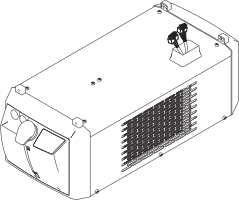
The cooling unit fits perfectly into the modular product design of the TransSteel power sources.
The cooling unit and power source together form a unit. As with the standalone power source, the power source/cooling unit combination can be mounted on the trolley.
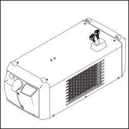
The cooling unit fits perfectly into the modular product design of the TransSteel power sources.
The cooling unit and power source together form a unit. As with the standalone power source, the power source/cooling unit combination can be mounted on the trolley.
The cooling unit fits perfectly into the modular product design of the TransSteel power sources.
The cooling unit and power source together form a unit. As with the standalone power source, the power source/cooling unit combination can be mounted on the trolley.
- FK 5000 (basic version)
- FK 5000 MV (Multivoltage version)
The FK 5000 MV adapts itself automatically to the mains voltage. The Multivoltage version is available only from the factory.
The scope of supply comprises:- Cooling unit
- 5 l coolant in a canister
- Four 5x25mm self-tapping screws
- Operating instructions
- water-cooled MIG/MAG manual welding torches
- Max. 8 hrs/day operation (single shift operation)
- Only original coolant from the manufacturer is used
- Regular maintenance and regular change of coolant
NOTE!
If used properly the coolant pump will have a service life of approx. 10,000 operating hours. After the end of its nominal service life, the coolant pump may develop a fault. To avoid a lengthy period of work disruption, the pump should be scheduled for replacement after approx. 10,000 operating hours.
CAUTION!
Danger from using non-permitted coolant.
This can result in severe damage to property.
Only use coolant available from the manufacturer. Other coolants are not recommended for electrical conductivity and material compatibility reasons.
Do not mix different coolants.
When changing the coolant, make sure all the coolant is replaced.
When switching from ethanol-based coolant to FCL 10/20 coolant, Change Kit FCL10 must be used and the instructions provided must be followed.
Operate the CU1200i Pro /MC exclusively with Cooling Liquid FCL10/20.
The shaft sealing surfaces inside the coolant pump are lubricated by the coolant, meaning that a certain leakage flow should always be expected. A low leakage flow is permitted.
The coolant pump requires a certain warm-up time after being started for the first time or upon restarting after a long period of downtime. An increased leakage flow can occur during this warm-up phase. The leakage flow will normally sink back down to a low level after the warm-up phase. If this is not the case then contact After-Sales Service.
As a result of firmware updates, you may find that your device has certain functions that are not described in these operating instructions, or vice versa. Certain illustrations may also differ slightly from the actual controls on your device, but these controls function in exactly the same way.
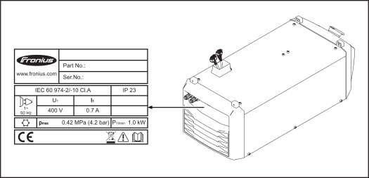
The cooling unit is fitted with safety symbols and a rating plate. The rating plate and safety symbols must not be removed or painted over. The symbols warn against operating the equipment incorrectly, as this may result in serious injury and damage.
| Welding is dangerous. The following basic requirements must be met to ensure the equipment is used properly: - Welders must be sufficiently qualified
- Suitable protective equipment must be used
- All persons not involved must be kept at a safe distance from the cooling unit and the welding process
|
| Do not use the functions described here until you have thoroughly read and understood the following documents: - this document
- all documents relating to the system components, especially the safety rules
|
| Do not dispose of used devices with domestic waste. Dispose of them according to the safety rules. |
The options listed below are available for all cooling unit variants.
The options listed below are available for all cooling unit variants.
Coolant temperature monitoring and flow monitoring are parts of an installation set and cannot be ordered separately. |
|
Coolant temperature monitoring
A temperature sensor monitors the coolant return temperature during welding. How it works:- If the temperature of the coolant exceeds 70 °C (158 °F):
- the wire-feed unit/power source outputs the service code "hot l H2O"
- the temperature sensor interrupts the welding current
- the cooling unit remains operational
- The temperature sensor restores the welding current when the coolant temperature falls to 65 °C (149 °F)
|
|
Flow monitoring
A flow sensor monitors the coolant flow during welding. How it works:- If the coolant flow drops below 0.7 l/min (0.18 gal./min [US])
- the wire-feed unit/power source outputs the service code "no l H2O"
- flow rate monitoring interrupts the welding current
- the cooling unit is switched off
|
The coolant filter is equipped with a CrNi screen, and its function is to filter dirt particles above 150 micrometers in size from the coolant. This ensures that no coarse dirt particles can pass into the coolant circuit. The coolant filter is fitted to the coolant return connection on the cooling unit.
The front coolant connections allow the cooling unit to be used in conjunction with power sources with an integrated wire drive (compact power sources).
The kit adds two additional coolant connections to the cooling unit. This allows the coolant filter to be mounted on the rear in a protected location and the welding torch to remain connected to the front as usual (compact power sources).
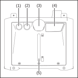
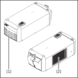
Front of cooling unit
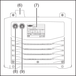
Rear of cooling unit
| (1) | Blanking cover - if the front coolant connections option is installed, then this is the coolant flow connection (blue)
|
| (2) | Blanking cover - if the front coolant connections option is installed, then this is the coolant return connection (red)
|
| (3) | Screw cap for coolant container |
| (4) | Operating and maintenance instructions |
| (5) | Coolant viewing window |
| (6) | Power source connecting plug |
| (7) | Rating plate |
| (8) | Coolant return connection (red) - if the front coolant connections option is installed, a blanking cover will be present
|
| (9) | Coolant flow connection (blue) - if the front coolant connections option is installed, a blanking cover will be present
|
Front of cooling unit
Rear of cooling unit
| (1) | Blanking cover - if the front coolant connections option is installed, then this is the coolant flow connection (blue)
|
| (2) | Blanking cover - if the front coolant connections option is installed, then this is the coolant return connection (red)
|
| (3) | Screw cap for coolant container |
| (4) | Operating and maintenance instructions |
| (5) | Coolant viewing window |
| (6) | Power source connecting plug |
| (7) | Rating plate |
| (8) | Coolant return connection (red) - if the front coolant connections option is installed, a blanking cover will be present
|
| (9) | Coolant flow connection (blue) - if the front coolant connections option is installed, a blanking cover will be present
|
Front of cooling unit
Rear of cooling unit
| (1) | Blanking cover - if the front coolant connections option is installed, then this is the coolant flow connection (blue)
|
| (2) | Blanking cover - if the front coolant connections option is installed, then this is the coolant return connection (red)
|
| (3) | Screw cap for coolant container |
| (4) | Operating and maintenance instructions |
| (5) | Coolant viewing window |
| (6) | Power source connecting plug |
| (7) | Rating plate |
| (8) | Coolant return connection (red) - if the front coolant connections option is installed, a blanking cover will be present
|
| (9) | Coolant flow connection (blue) - if the front coolant connections option is installed, a blanking cover will be present
|
WARNING!
Danger due to incorrect operation and incorrectly performed work.
This can result in serious injury and damage to property.
All the work and functions described in this document must only be carried out by technically trained and qualified personnel.
Fully read and understand this document.
Read and understand all safety rules and user documentation for this device and all system components.
WARNING!
Danger due to incorrect operation and incorrectly performed work.
This can result in serious injury and damage to property.
All the work and functions described in this document must only be carried out by technically trained and qualified personnel.
Fully read and understand this document.
Read and understand all safety rules and user documentation for this device and all system components.
WARNING!
Danger due to incorrect operation and incorrectly performed work.
This can result in serious injury and damage to property.
All the work and functions described in this document must only be carried out by technically trained and qualified personnel.
Fully read and understand this document.
Read and understand all safety rules and user documentation for this device and all system components.
WARNING!
Danger from machines toppling over or falling.
This can result in serious personal injury and damage to property.
Set up the device securely on an even, solid surface.
Check all screw connections are tightly fastened after installation.
WARNING!
Danger from electric current.
This can result in serious personal injury and damage to property.
Ensure the cooling unit is properly insulated.
Always ensure that there is no electrically conductive connection between the base plate of the cooling unit and the surface.
Before installing the cooling unit, remove all electrically conductive parts between the base plate of the cooling unit and the surface.
- Protection against penetration by solid foreign bodies with diameters greater than 12.5 mm (0.49 in.)
- Protection against spraywater at any angle up to 60° to the vertical
Cooling air
The system must be set up in such a way that the cooling air can flow unimpeded through the slots in the side panels. Ensure that there is always an all-round clearance of 0.5 m (1 ft. 7.69 in.) around the device.
Air inlet openings and air outlet openings
CAUTION!
Danger from insufficient cooling air supply.
This can result in severe damage to property.
Air inlet openings (1) and outlet openings (2) must never be covered, not even partially.
Dust
Ensure that any metallic dust, for example from grinding work, is not sucked into the system by the fan.
Outdoor operation
The device can be set up and operated outdoors in accordance with degree of protection IP23. Avoid direct wetting (e.g. from rain).
The cooling unit is delivered empty.
Use only original Fronius coolant (Cooling Liquid FCL 10/20 or torch coolant) when filling the cooling unit. Other coolants are not recommended for electrical conductivity and material compatibility reasons.
The coolant pump may only be used with original coolant supplied by the manufacturer. Do not allow the coolant pump to run dry (even for a very short time), as this will destroy the coolant pump. The manufacturer accepts no liability for damage caused in such cases.
The device is intended solely for use in conjunction with Fronius system components.
The device is to be used exclusively for its intended purpose.
Any use above and beyond this purpose is deemed improper.
Proper use also includes:- Fully reading and understanding these Operating Instructions
- Following all the instructions and safety rules in these Operating Instructions
- Performing all stipulated inspection and servicing work
The device is designed for use in industry and the workshop. The manufacturer accepts no responsibility for any damage caused through use in a domestic setting.
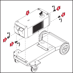
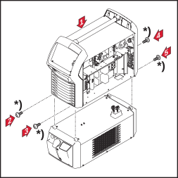
The welding system can be fitted to a trolley to make the system (incl. cooling unit) more mobile.
The welding system can be fitted to a trolley to make the system (incl. cooling unit) more mobile.
*) TU Car 4 Pro scope of supply
WARNING!
Danger from electric current.
An electric shock can be fatal.
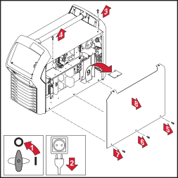
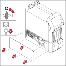
Before starting the work described below:
Turn the power source mains switch to the "O" position.
Disconnect the power source from the mains.
Ensure that the power source remains disconnected from the mains until all work has been completed.
After opening the device, use a suitable measuring instrument to check that electrically charged components (e.g. capacitors) have been discharged.
WARNING!
Danger from inadequate ground conductor connections.
This can result in severe personal injury and damage to property.
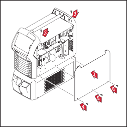
The housing screws provide a suitable ground conductor connection for earthing the housing and must NOT be replaced by any other screws that do not provide a reliable ground conductor connection.
WARNING!
Danger from electric current.
An electric shock can be fatal.
Before starting the work described below:
Turn the power source mains switch to the "O" position.
Disconnect the power source from the mains.
Ensure that the power source remains disconnected from the mains until all work has been completed.
After opening the device, use a suitable measuring instrument to check that electrically charged components (e.g. capacitors) have been discharged.
WARNING!
Danger from inadequate ground conductor connections.
This can result in severe personal injury and damage to property.
The housing screws provide a suitable ground conductor connection for earthing the housing and must NOT be replaced by any other screws that do not provide a reliable ground conductor connection.
CAUTION!
Risk of short circuit from kinked or damaged cables.
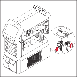
When connecting the power source to the cooling unit, ensure that the cables are not kinked.
*) Cooling unit scope of supply
WARNING!
Danger from electrical current.
This can result in serious personal injury and damage to property.
Before starting work, switch off all devices and components involved and disconnect them from the grid.
Secure all devices and components involved so they cannot be switched back on.
WARNING!
Danger from electrical current.
This can result in serious personal injury and damage to property.
Before starting work, switch off all devices and components involved and disconnect them from the grid.
Secure all devices and components involved so they cannot be switched back on.
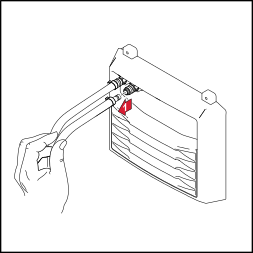
1NOTE!
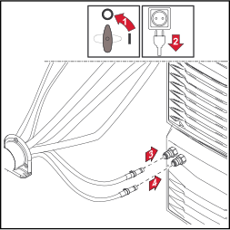
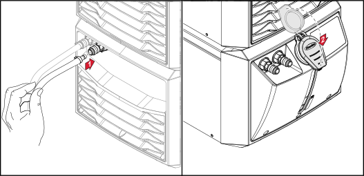
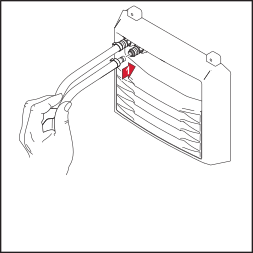
Connect the colour-coded coolant hoses to the corresponding coolant flow and return connections on the cooling unit.
1NOTE!
Connect the coloured coolant hoses to the corresponding coolant flow and return connections on the cooling unit.
WARNING!
Danger from electrical current.
This can result in serious personal injury and damage to property.
Before starting work, switch off all devices and components involved and disconnect them from the grid.
Secure all devices and components involved so they cannot be switched back on.
WARNING!
Danger from coolant leakage.
This can result in serious personal injury and damage to property.
If there is any coolant on the exterior of the cooling unit, remove it immediately.
Make sure that no coolant gets into the interior of the cooling unit.
CAUTION!
Danger due to work that has been carried out incorrectly.
This can result in severe damage to property.
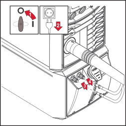
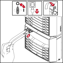
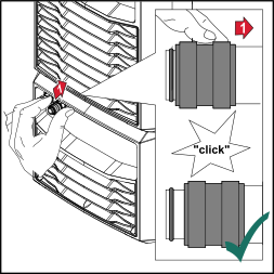
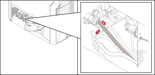
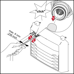
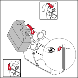
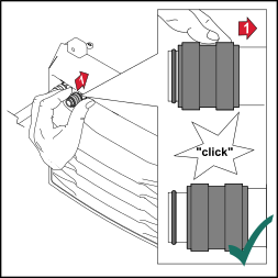
If the coolant connections are on the front of the cooling unit, carry out the following steps as shown – but at the front coolant flow connection (blue).
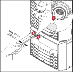
2Push the sealing cone in the coolant flow connection backwards
4Push the locking ring backwards until the sealing cone returns to its original position and release the locking ring again
WARNING!
Danger from electrical current.
This can result in serious personal injury and damage to property.
Before starting work, switch off all devices and components involved and disconnect them from the grid.
Secure all devices and components involved so they cannot be switched back on.
WARNING!
Danger from coolant leakage.
This can result in serious personal injury and damage to property.
If there is any coolant on the exterior of the cooling unit, remove it immediately.
Make sure that no coolant gets into the interior of the cooling unit.
CAUTION!
Danger due to work that has been carried out incorrectly.
This can result in severe damage to property.
If the coolant connections are on the front of the cooling unit, carry out the following steps as shown – but at the front coolant flow connection (blue).
2Push the sealing cone in the coolant flow connection backwards
4Push the locking ring backwards until the sealing cone returns to its original position and release the locking ring again
NOTE!
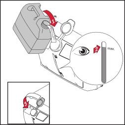
Before starting up the cooling unit, first check that it contains an adequate amount of coolant and that the coolant is clean and uncontaminated.
NOTE!
During welding, check at regular intervals that the coolant is flowing properly.
You should be able to see a steady return flow of coolant into the coolant container.
The cooling unit is powered from the power source. If the power source mains switch is turned to position "I", the cooling unit will also start to operate.
WARNING!
Danger from electrical current.
This can result in serious personal injury and damage to property.
Before starting work, switch off all devices and components involved and disconnect them from the grid.
Secure all devices and components involved so they cannot be switched back on.
WARNING!
This can result in serious burns or scalding.
Before carrying out any work, allow the coolant to cool to +25 °C / +77 °F.
WARNING!
Danger from coolant leakage.
This can result in serious personal injury and damage to property.
If there is any coolant on the exterior of the cooling unit, remove it immediately.
Make sure that no coolant gets into the interior of the cooling unit.
WARNING!
Danger from electrical current.
This can result in serious personal injury and damage to property.
Before starting work, switch off all devices and components involved and disconnect them from the grid.
Secure all devices and components involved so they cannot be switched back on.
WARNING!
This can result in serious burns or scalding.
Before carrying out any work, allow the coolant to cool to +25 °C / +77 °F.
WARNING!
Danger from coolant leakage.
This can result in serious personal injury and damage to property.
If there is any coolant on the exterior of the cooling unit, remove it immediately.
Make sure that no coolant gets into the interior of the cooling unit.
NOTE!
Make sure that no coolant enters the device.
If there is any coolant on the exterior of the device, remove it immediately.
NOTE!
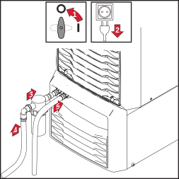
If the coolant connections are on the front of the cooling unit, fit the coolant filter in the same way.
Connect the coolant filter to the coolant return connection (red) on the front of the cooling unit.
WARNING!
Danger from incorrect operation and work that is not carried out properly.
This can result in serious personal injury and damage to property.
All the work and functions described in this document must only be carried out by technically trained and qualified personnel.
Read and understand this document in full.
Read and understand all safety rules and user documentation for this device and all system components.
WARNING!
Danger from electrical current.
This can result in serious personal injury and damage to property.
Before starting work, switch off all devices and components involved and disconnect them from the grid.
Secure all devices and components involved so they cannot be switched back on.
WARNING!
Danger due to insufficient ground conductor connection.
This can result in serious personal injury and damage to property.
The housing screws provide a suitable ground conductor connection for grounding the housing.
The housing screws must not under any circumstances be replaced by other screws without a reliable ground conductor connection.
WARNING!
Danger from coolant leakage.
This can result in serious personal injury and damage to property.
If there is any coolant on the exterior of the cooling unit, remove it immediately.
Make sure that no coolant gets into the interior of the cooling unit.
WARNING!
This can result in serious burns or scalding.
Before carrying out any work, allow the coolant to cool to +25 °C / +77 °F.
WARNING!
Danger from incorrect operation and work that is not carried out properly.
This can result in serious personal injury and damage to property.
All the work and functions described in this document must only be carried out by technically trained and qualified personnel.
Read and understand this document in full.
Read and understand all safety rules and user documentation for this device and all system components.
WARNING!
Danger from electrical current.
This can result in serious personal injury and damage to property.
Before starting work, switch off all devices and components involved and disconnect them from the grid.
Secure all devices and components involved so they cannot be switched back on.
WARNING!
Danger due to insufficient ground conductor connection.
This can result in serious personal injury and damage to property.
The housing screws provide a suitable ground conductor connection for grounding the housing.
The housing screws must not under any circumstances be replaced by other screws without a reliable ground conductor connection.
WARNING!
Danger from coolant leakage.
This can result in serious personal injury and damage to property.
If there is any coolant on the exterior of the cooling unit, remove it immediately.
Make sure that no coolant gets into the interior of the cooling unit.
WARNING!
This can result in serious burns or scalding.
Before carrying out any work, allow the coolant to cool to +25 °C / +77 °F.
WARNING!
Danger from incorrect operation and work that is not carried out properly.
This can result in serious personal injury and damage to property.
All the work and functions described in this document must only be carried out by technically trained and qualified personnel.
Read and understand this document in full.
Read and understand all safety rules and user documentation for this device and all system components.
WARNING!
Danger from electrical current.
This can result in serious personal injury and damage to property.
Before starting work, switch off all devices and components involved and disconnect them from the grid.
Secure all devices and components involved so they cannot be switched back on.
WARNING!
Danger due to insufficient ground conductor connection.
This can result in serious personal injury and damage to property.
The housing screws provide a suitable ground conductor connection for grounding the housing.
The housing screws must not under any circumstances be replaced by other screws without a reliable ground conductor connection.
WARNING!
Danger from coolant leakage.
This can result in serious personal injury and damage to property.
If there is any coolant on the exterior of the cooling unit, remove it immediately.
Make sure that no coolant gets into the interior of the cooling unit.
WARNING!
This can result in serious burns or scalding.
Before carrying out any work, allow the coolant to cool to +25 °C / +77 °F.
Make a note of the serial number and configuration of the device and contact our After-Sales Service team with a detailed description of the error, if
- errors occur that are not listed below
- the troubleshooting measures listed are unsuccessful
Insufficient or no coolant flow| Cause: | Coolant level too low |
| Remedy: | Top up coolant |
| Cause: | Constriction or foreign body in cooling circuit |
| Remedy: | Remove constriction or foreign body |
| Cause: | Coolant contaminated |
| Remedy: | Change the coolant |
| Cause: | Coolant filter (option) misplaced when connecting coolant return |
| Remedy: | Clean coolant filter/replace filter element |
| Cause: | Coolant pump sticking |
| Remedy: | Turn coolant pump shaft (see operating instructions, "Turning coolant pump shaft" section). Contact After-Sales Service if the coolant pump shaft proves impossible to turn |
| Cause: | Coolant pump defective |
| Remedy: | Contact After-Sales Service |
Coolant pump does not work after turning the coolant pump shaft| Cause: | Temperature switch on coolant pump has tripped |
| Remedy: | Wait until the end of the coolant pump's cooling phase (2 - 3 minutes) |
Insufficient cooling power| Cause: | Cooler contaminated |
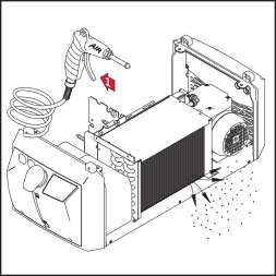
| Remedy: | Gas purge cooler with dry compressed air |
| Cause: | Faulty fan |
| Remedy: | Contact After-Sales Service |
| Cause: | Coolant pump defective |
| Remedy: | Contact After-Sales Service |
High operating noise level| Cause: | Coolant level too low |
| Remedy: | Top up coolant |
| Cause: | Coolant pump defective |
| Remedy: | Contact After-Sales Service |
The welding torch becomes very hot| Cause: | The specification of the cooling unit is inadequate |
| Remedy: | Observe the duty cycle and loading limits |
| Cause: | The specification of the welding torch is inadequate |
| Remedy: | Observe the duty cycle and loading limits |
| Cause: | Inadequate coolant flow |
| Remedy: | Check coolant level. Top up with coolant if necessary.
Check coolant for contamination. Change the coolant if necessary |
| Cause: | Inadequate coolant flow |
| Remedy: | Coolant pump sticking: Turn coolant pump shaft (see operating instructions, "Turning coolant pump shaft" section). Contact After-Sales Service if the coolant pump shaft proves impossible to turn |
NOTE!
Depending on the welding system, the service codes are displayed on the power source or the wire-feed unit.
hot l H2OThe optional coolant temperature sensor in the cooling unit has tripped.
| Cause: | Coolant temperature too high |
| Remedy: | Wait until the end of the cooling phase, i.e. until "hot | H2O" is no longer displayed.
If using a ROB 5000 or field bus coupler for robot control: After completion of troubleshooting and before resuming welding, set the "Source error reset" signal. |
no l H2OThe optional cooling unit flow sensor has tripped.
| Cause: | Coolant flow problem |
| Remedy: | Check coolant level. Top up with coolant if necessary.
Check coolant for contamination. Change the coolant if necessary |
| Cause: | Coolant filter (option) misplaced when connecting coolant return |
| Remedy: | Clean coolant filter/replace filter element |
WARNING!
Danger due to work that has been carried out incorrectly.
This can result in severe personal injury and damage to property
All the work described below must only be carried out by trained and qualified personnel.
Fully read and understand this document.
Fully read and understand all the Operating Instructions for the system components, especially the safety rules.
WARNING!
Danger from electric current.
An electric shock can be fatal.
Turn the power source mains switch to the "O" position.
Disconnect the power source from the mains.
Ensure that the power source remains disconnected from the mains until all work has been completed.
WARNING!
Danger due to work that has been carried out incorrectly.
This can result in severe personal injury and damage to property
All the work described below must only be carried out by trained and qualified personnel.
Fully read and understand this document.
Fully read and understand all the Operating Instructions for the system components, especially the safety rules.
WARNING!
Danger from electric current.
An electric shock can be fatal.
Turn the power source mains switch to the "O" position.
Disconnect the power source from the mains.
Ensure that the power source remains disconnected from the mains until all work has been completed.
WARNING!
Danger from incorrect operation and work that is not carried out properly.
This can result in serious personal injury and damage to property.
All the work and functions described in this document must only be carried out by technically trained and qualified personnel.
Read and understand this document in full.
Read and understand all safety rules and user documentation for this device and all system components.
WARNING!
Danger from electrical current.
This can result in serious personal injury and damage to property.
Before starting work, switch off all devices and components involved and disconnect them from the grid.
Secure all devices and components involved so they cannot be switched back on.
After opening the device, use a suitable measuring instrument to check that electrically charged components (such as capacitors) have been discharged.
WARNING!
Danger due to insufficient ground conductor connection.
This can result in serious personal injury and damage to property.
The housing screws provide a suitable ground conductor connection for grounding the housing.
The housing screws must not under any circumstances be replaced by other screws without a reliable ground conductor connection.
WARNING!
Danger from coolant leakage.
This can result in serious personal injury and damage to property.
Immediately remove any coolant that enters the device or spills onto its exterior during the work described in the following.
WARNING!
This can result in serious burns or scalding.
Before carrying out any work, allow the coolant to cool to +25 °C / +77 °F.
WARNING!
Danger from incorrect operation and work that is not carried out properly.
This can result in serious personal injury and damage to property.
All the work and functions described in this document must only be carried out by technically trained and qualified personnel.
Read and understand this document in full.
Read and understand all safety rules and user documentation for this device and all system components.
WARNING!
Danger from electrical current.
This can result in serious personal injury and damage to property.
Before starting work, switch off all devices and components involved and disconnect them from the grid.
Secure all devices and components involved so they cannot be switched back on.
After opening the device, use a suitable measuring instrument to check that electrically charged components (such as capacitors) have been discharged.
WARNING!
Danger due to insufficient ground conductor connection.
This can result in serious personal injury and damage to property.
The housing screws provide a suitable ground conductor connection for grounding the housing.
The housing screws must not under any circumstances be replaced by other screws without a reliable ground conductor connection.
WARNING!
Danger from coolant leakage.
This can result in serious personal injury and damage to property.
Immediately remove any coolant that enters the device or spills onto its exterior during the work described in the following.
WARNING!
This can result in serious burns or scalding.
Before carrying out any work, allow the coolant to cool to +25 °C / +77 °F.
WARNING!
Danger from incorrect operation and work that is not carried out properly.
This can result in serious personal injury and damage to property.
All the work and functions described in this document must only be carried out by technically trained and qualified personnel.
Read and understand this document in full.
Read and understand all safety rules and user documentation for this device and all system components.
WARNING!
Danger from electrical current.
This can result in serious personal injury and damage to property.
Before starting work, switch off all devices and components involved and disconnect them from the grid.
Secure all devices and components involved so they cannot be switched back on.
After opening the device, use a suitable measuring instrument to check that electrically charged components (such as capacitors) have been discharged.
WARNING!
Danger due to insufficient ground conductor connection.
This can result in serious personal injury and damage to property.
The housing screws provide a suitable ground conductor connection for grounding the housing.
The housing screws must not under any circumstances be replaced by other screws without a reliable ground conductor connection.
WARNING!
Danger from coolant leakage.
This can result in serious personal injury and damage to property.
Immediately remove any coolant that enters the device or spills onto its exterior during the work described in the following.
WARNING!
This can result in serious burns or scalding.
Before carrying out any work, allow the coolant to cool to +25 °C / +77 °F.
Under normal operating conditions, the device requires only a minimum of care and maintenance. However, it is vital to observe some important points to ensure the device remains in a usable condition for many years.
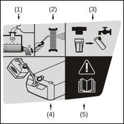
| (1) | Change the coolant |
| (2) | Gas purge the cooler |
| (3) | Clean the coolant return filter on the outside of the unit and the coolant pre-filter inside the unit and replace the filter element if necessary |
| (4) | Only use original coolant from the manufacturer (Cooling Liquid FCL 10/20 oder ethanolbasiertes Kühlmittel) |
| (5) | Read this document |
The relevant maintenance intervals and work are described in detail in the following pages.
CAUTION!
Danger due to starting up without coolant.
This can result in severe damage to property.
Only operate the cooling unit after it has been filled with coolant.
If water-cooled system components are put into operation without coolant, this usually results in a defect of the system components.
The manufacturer is not liable for any resulting damage, and all warranty claims are voided
CAUTION!
Danger from non-permitted coolant.
This can result in severe damage to property.
Use only original coolant from the manufacturer (Cooling Liquid FCL 10/20 or ethanol-based coolant) when filling the cooling unit.
Other coolants are not recommended for electrical conductivity and material compatibility reasons.
- Ensure that all hosepacks and welding torches are undamaged
- Check that there is an all-round clearance of 0.5 m (1 ft. 7.69 in.) to ensure that cooling air can flow in and out freely
- Check the screw connections between all system components of the welding system for tightness
- Check all the coolant connections of the welding system for tightness
- Monitor the coolant return flow in the coolant tank
- If no coolant is returning to the container, identify and remedy the cause
- Check coolant level. If the coolant level is below the "min" mark, top up with coolant. Attention when using OPT/CU Torch deflate - see section Maintenance intervals, maintenance work from page (→).
- Check the purity of the coolant. Change the coolant if necessary
- If present: clean the coolant return filter on the outside of the unit and replace the filter element if necessary
- Gas purge the cooler
- Change the coolant
- Change the ethanol-based coolant
CU1200i Pro /MC only:
- clean the coolant pre-filter in the interior of the unit and replace the filter element if necessary
IMPORTANT! Cleaning the pre-filter and replacing the filter element must be documented by the operator of the device!
Every 24 months in single-shift operation with FCL 10/20 coolantCAUTION!
Risk from gas purging the cooler.
This may result in damage to electronic components.
Always follow the instructions in the "Safety" section at the start of the "Care, maintenance and disposal" chapter.
Do not bring the air nozzle too close to electronic components.
For the sake of clarity, the cooling unit is shown in the following figures without the power source. However, the power source can remain on the cooling unit when gas purging the cooler.
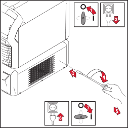
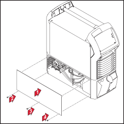
- Remove the device side panels and clean the cooler
- remove device side panels and clean inside of device with dry, reduced compressed air.
CAUTION!
Risk of injury and material damage from the welding current and accidental ignition of an arc.
Before starting work:
disconnect the ground earth connection between the welding system and the workpiece
remove the wire electrode from the welding torch being used
depending on the system, remove the wirespool or the basket-type spool from the power source or the wire-feed unit
NOTE!
The coolant must not be disposed of in the public sewage system.
Dispose of coolant in accordance with the applicable local and national regulations.
NOTE!
Use only original Fronius coolant when refilling the cooling unit.
NOTE!
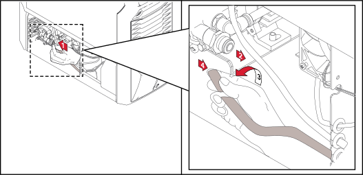
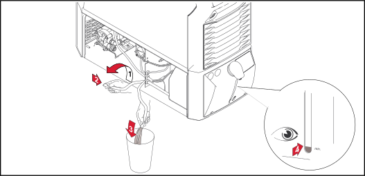
Seal off the coolant hose as soon as it is pulled out of the coolant pump connection.
This will ensure that as little coolant as possible enters the device. Immediately remove any coolant that enters the device or spills onto its exterior.
NOTE!
If the coolant connections are on the front of the cooling unit, carry out the following steps as shown - but at the front coolant flow connection (blue).
10Ensure that all hose connections are properly established and are not leaking
11Ensure that there is no coolant inside the device or on its exterior
Dispose of in accordance with the applicable national and local regulations.
The cooling capacity of a cooling unit depends on- Ambient temperature
- Delivery head
- Flow rate Q (l/min) - The flow rate Q depends on the length of the interconnecting hosepack and the diameter of the hose.
- Ambient temperature
- Delivery head
- Flow rate Q (l/min) - The flow rate Q depends on the length of the interconnecting hosepack and the diameter of the hose.
- Ambient temperature
- Delivery head
- Flow rate Q (l/min) - The flow rate Q depends on the length of the interconnecting hosepack and the diameter of the hose.
| FK 5000 | FK 5000 MV |
|---|
Mains voltage | 400 V AC | 200-230/400-480 V AC |
Mains voltage tolerance | -10% / +10% | -10% / +10% |
Mains frequency | 50 / 60 Hz | 50 / 60 Hz |
Current input | 0.6 / 0.7 A | 0.6 / 1.4 A |
Cooling power at
Q = 1 l/min + 25 °C (77 °F)
Q = 1l / min + 40 °C (104 °F)
Q = max. + 25 °C (77 °F)
Q = max. + 40 °C (104 °F) |
1000 W
800 W
1500 W
1000 W
|
1000 W
800 W
1500 W
1000 W
|
Max. delivery head | 35 m
114 ft. 9.95 in. | 35 m
114 ft. 9.95 in. |
Max. delivery rate | 3.5 l/min
0.92 gal./min [US] | 3.5 l/min
0.92 gal./min [US] |
Max. pump pressure | 4.2 bar
60.89 psi | 4.2 bar
60.89 psi |
Pump | Centrifugal pump | Centrifugal pump |
Pump service life | approx. 10,000 hrs | approx. 10,000 hrs |
Coolant capacity | 6 l
1.59 gal. [US] | 6 l
1.59 gal. [US] |
Protection class | IP 23 | IP 23 |
Dimensions l/w/h | 710/300/230 mm
27.95/11.81/9.06 in. | 710/300/230 mm
27.95/11.81/9.06 in. |
Weight (without coolant) | 13.6 kg
29.98 Ib. | 16 kg
35.27 lb. |
Flow monitoring* | Sensor
error below 0.7 l/min (0.18 gal./min) | Sensor
error below 0.7 l/min (0.18 gal./min) |
Coolant temperature monitoring* | Error above 70 °C (158 °F) | Error above 70 °C (158 °F) |
Mark of conformity | CE | CE |
* Optional