Safety Instructions
Explanation of Safety Instructions
DANGER!
Indicates an immediate danger.
Death or serious injury may result if appropriate precautions are not taken.
WARNING!
Indicates a possibly dangerous situation.
Death or serious injury may result if appropriate precautions are not taken.
CAUTION!
Indicates a situation where damage or injury could occur.
Minor injury or damage to property may result if appropriate precautions are not taken.
NOTE!
Indicates the possibility of flawed results and damage to the equipment.
General
- Serious or fatal injury to the operator or third parties
- Damage to the device and other material assets belonging to the operating company
- Inefficient operation of the device
- Be suitably qualified
- Have fully read, understood, and precisely followed these Operating Instructions
The Operating Instructions must always be kept to hand wherever the device is being used. In addition to the Operating Instructions, all applicable local rules and regulations regarding accident prevention and environmental protection must also be followed.
All safety and danger notices on the device:- Must be kept in a legible state
- Must not be damaged/marked
- Must not be removed
- Must not be covered, pasted, or painted over
For the location of the safety and danger notices on the device, refer to the section headed "General" in the Operating Instructions for the device.
Before switching on the device, remove any faults that could compromise safety.
Your personal safety is at stake!
Environmental conditions
Operation or storage of the device outside the stipulated area will be deemed as not in accordance with the intended purpose. The manufacturer accepts no liability for any damage resulting from improper use.
Installation and operation may only take place within closed and dry rooms.
Temperature range of ambient air:- During operation: - 10 °C to + 35 °C (14 °F to 95 °F)
- During transport and storage: - 25 °C to + 55 °C (- 13 °F to 131 °F)
- up to 50% at 35 °C (95 °F)
- up to 90% at 20 °C (68 °F)
Ambient air: free of dust, acids, corrosive gases or substances, etc.
Altitude above sea level: up to 2000 m (6500 ft.)
Obligations of the operating company
- Read and understand the Operating Instructions
- Only hand over the device keys to personnel who are familiar with the product
- Are familiar with the basic occupational safety and accident prevention regulations and are trained in handling the device
- Have read and understood these Operating Instructions and have confirmed this with their signature
- Are trained according to the requirements for the work and training results.
The safety-conscious work of the personnel must be checked regularly.
Obligations of personnel
- Follow the basic regulations for occupational safety and accident prevention
- Have read and understood these Operating Instructions.
Before leaving the workplace, ensure that no personal injury or property damage can occur in their absence.
Mains connection
The mains voltage and grid frequency must match the specifications on the rating plate.
The Virtual Welding system must only be connected to a properly installed, secured, and grounded mains socket.
If the device is supplied without a country-specific cable, use the mains plug and cable in accordance with local standards.
An electric shock can be fatal. Only trained personnel may install and connect the mains plug.
Route the mains cable so that there is no risk of injury (risk of tripping, etc.) and damage to the mains cable.
Danger from mains current
An electric shock can be fatal.
Do not touch voltage-carrying parts inside or outside the device.
All cables and leads must be secured, undamaged, insulated, and adequately dimensioned. Replace loose connections and scorched, damaged, or inadequately dimensioned cables and leads immediately.
Do not wrap cables or leads around your body or parts of the body.
Have the mains and device supply lead regularly inspected by an electrician to ensure that the ground conductor is functioning properly.
Only operate the device on a grid with a ground conductor and a socket with a ground conductor contact.
Operating the device on a grid without a ground conductor and on a socket without a ground conductor contact is considered gross negligence. The manufacturer accepts no liability for any damage resulting from improper use.
Switch off unused devices.
When working at elevated heights, wear a safety harness to prevent falls.
Before working on the device, switch off the device and remove the mains plug.
Secure the device to prevent the mains plug from being connected and switched on again by applying a clearly legible and understandable warning sign.
After opening the device:- Discharge all electrically charged components
- Ensure that all components are disconnected from the power supply
If work is needed on voltage-carrying parts, bring in a second person who will switch off the main switch at the correct time.
Repair work (e.g., opening the device) must only be carried out by qualified personnel trained for this purpose. If a defect occurs, unplug the device immediately and have the repair carried out by trained and qualified personnel.
- Repairs must only be carried out in a de-energized state
- Only use original spare parts
- Only unplug the device when it is switched off
EMC device classifications
The Virtual Welding system is an emission class A device
Devices in emission class A- Are only designed for use in industrial areas
- Can cause wiring-related or radiated interference in other areas.
In certain cases, even though a device complies with the standard limit values for emissions, it may affect the application area for which it was designed (e.g., when there is sensitive equipment at the same location, or if the site where the device is installed is close to either radio or television receivers).
If this is the case, then the operating company is obliged to take appropriate action to rectify the situation.
- Safety devices
- Mains power lines, signal lines, and data transfer lines
- IT and telecommunications equipment
- Devices for measuring and calibrating
- Mains power supply
- Use only the supplied power cables
- If electromagnetic interference occurs despite a mains connection that complies with regulations, take additional measures (e.g., use a suitable mains filter).
- No modifications to the device
- Modifications made to the device without prior agreement with the manufacturer may result in loss of type approval
- If the device is suspected of interfering with the reception of television or radio signals or the operation of another device:
- Confirm the device by switching it on and off as a source of interference
- If this identifies the device as a source of interference, remedy the fault using the anti-interference measures listed below
- Anti-interference measures
- Shield other devices in the vicinity
- Place the device far away from the affected receiver
- Turn the device away from the affected receiver
- Adjust the antenna of the affected receiver
- Connect the device to another AC socket so that the device and the affected receiver use different circuits.
- Only connect the device to a grounded socket. Removing the grounding may increase high-frequency emissions and cause an electric shock resulting in death. Do not use AC adapter plugs or extension cables
- If the above measures do not provide a sustainable solution, contact the manufacturer or a trained radio and television technician
Particular hazard areas
Special regulations apply in areas at risk of fire or explosion
–follow the appropriate national and international regulations.
Always keep ventilation openings clear. For more information on the position of the ventilation openings, see section Position of the ventilation openings from page (→).
The ambient temperature must not exceed 35 °C (95 °F).
The device must not be transported using a crane.
Risk of personal injury due to toppling of the StandUp Terminal if set up incorrectly. Only set up the StandUp Terminal on a flat, stable surface and screw it to the wall and floor using the supplied brackets with the help of trained personnel.
For more information on installing the StandUp Terminal, see section Installing the Standup Terminal from page (→).
Safety measures at the setup location and during transport
Take care to ensure that the applicable national and regional guidelines and accident prevention regulations are observed when transporting the device. especially guidelines concerning hazards during transport and shipment.
Only carry out the transport in the original packaging. The original packaging is available from the manufacturer.
Do not lift or transport any active devices. Switch off devices before transport or lifting.
Carry out internal instructions and checks to ensure that the vicinity of the workplace is always clean and organized.
After transport and before installation and commissioning, it is essential to visually inspect the device for damage. Have a trained service technician repair any damage before installation and commissioning.
Safety measures in normal operation
- Serious or fatal injury to the operator or third parties
- Damage to the device and other material assets belonging to the operating company
- Inefficient operation of the device
Safety devices that are not fully functional must be repaired before the device is switched on.
Never bypass or disable safety devices.
Before switching on the device, ensure that no one can be put in danger.
The device must be examined at least once a week for externally detectable damage and functionality of the safety devices.
Maintenance and repair
It is impossible to guarantee that bought-in parts are designed and manufactured to meet the demands made of them, or that they satisfy safety requirements.
- Use only original spare and wearing parts (also applies to standard parts).
- Do not carry out any modifications, alterations, etc. to the device without the manufacturer's consent.
- Components that are not in perfect condition must be replaced immediately.
- When ordering, please give the exact designation and part number as shown in the spare parts list, as well as the serial number of your device.
The housing screws provide the ground conductor connection for earthing the housing parts.
Only use original housing screws in the correct number and tightened to the specified torque.
Safety symbols
Devices with the CE label satisfy the essential requirements of the low-voltage and electromagnetic compatibility directive (e.g., relevant product standards of the EN 60974 series).
Fronius International GmbH declares that the device complies with Directive 2014/53/EU. The full text of the EU Declaration of Conformity is available on the following website: http://www.fronius.com
Devices marked with the CSA test mark satisfy the requirements of the relevant standards for Canada and the USA.
Data backup
The user is responsible for backing up any changes made to the factory settings. The manufacturer accepts no liability for any deleted personal settings.
Copyright
Copyright of these Operating Instructions remains with the manufacturer.
Text and illustrations were accurate at the time of printing. Fronius reserves the right to make changes. The contents of the Operating Instructions shall not provide the basis for any claims whatsoever on the part of the purchaser. If you have any suggestions for improvement, or can point out any mistakes that you have found in the Operating Instructions, we will be most grateful for your comments.
Disposal
To comply with European directives and national law, waste electrical and electronic equipment must be collected separately and sent for environmentally-friendly recycling. Used devices must be returned to a distributor or an approved collection and recycling facility in your area. Proper disposal of used devices promotes the sustainable recycling of material resources. Ignoring this may have potentially adverse effects on the environment and your health.
Packaging materials
Materials collected separately. Check the regulations in your area. Reduce the volume of cardboard.
General information
General
Device concept

StandUp Terminal
Virtual Welding is used for the realistic learning of welding skills. Virtual Welding offers the following benefits:- Very low cost of training. No consumables are required (wire electrodes, welding gas, etc.)
- The trainees are not exposed to the dangers of welding (heat, welding fumes, welding spatter, noise, etc.)
- The learning progress of the trainees is documented and can be compared
- The learning content can be adapted to suit individual needs
- With the help of the various welding torches and workpieces, many different tasks can be simulated
- etc.
The Virtual Welding system is available as a StandUp Terminal for stationary use and as a MobileCase for mobile use.

MobileCase
General
Device concept
StandUp Terminal
Virtual Welding is used for the realistic learning of welding skills. Virtual Welding offers the following benefits:- Very low cost of training. No consumables are required (wire electrodes, welding gas, etc.)
- The trainees are not exposed to the dangers of welding (heat, welding fumes, welding spatter, noise, etc.)
- The learning progress of the trainees is documented and can be compared
- The learning content can be adapted to suit individual needs
- With the help of the various welding torches and workpieces, many different tasks can be simulated
- etc.
The Virtual Welding system is available as a StandUp Terminal for stationary use and as a MobileCase for mobile use.
MobileCase
Intended use
The device is to be used exclusively for its intended purpose.
The device is intended for welding simulation only with the software and hardware supplied by the manufacturer.
Utilization for any other purpose, or in any other manner shall be deemed improper.
The manufacturer shall not be liable for any resulting damage.
- Carefully reading and adhering to all instructions in these Operating Instructions
- Carefully reading and understanding all warnings on the device
- Carrying out all the specified inspection and maintenance work
- Establishing the mains connection according to the specifications on the rating plate
- Installation in closed and dry rooms
- Convert the device yourself
- Handle the device incorrectly
- Operate the device with programs other than the manufacturer's software
- Operate, service, or repair the device without observing the Operating Instructions
The device is designed for operation in closed and dry rooms. The manufacturer shall not be liable for any damage resulting from use in other environments.
The manufacturer shall also not be liable for faulty or incorrect training success.
Warning notices on the device
Warning notices and safety symbols can be found on the StandUp Terminal and MobileCase. These warning notices and safety symbols must not be removed or painted over. They warn against incorrect operation, as this may result in serious injury and property damage.


- These Operating Instructions
- All system component Operating Instructions, especially the safety rules

Dispose of old devices in accordance with safety rules and not in normal domestic waste.
Software and product updates
Because of software updates, certain functions may be available for your device but not described in these Operating Instructions or vice versa. In addition, individual figures may also differ slightly from the operating controls of your device. However, these operating controls function in exactly the same way.
Scope of supply and optional function packages
Scope of supply
In addition to StandUp Terminal or the MobileCase, the following system components are included in the scope of supply:

Work table

Workpiece holder

Single-V butt weld workpiece, layer 1 (square butt weld)

Single-V butt weld workpiece, layer 2 and 3 (square butt weld)

Fillet weld workpiece

Pipe workpiece

2 NFC keys
- 3D glasses
- 4 keys
- 4 M8 x 80 mm screws with washers, for screwing together the upper and lower parts
- Mounting bracket including 4 M8x16 mm screws and washers
- This document
- Mains cable (for connecting to a socket)
- Cable for 3D glasses
- Network cable
- 3D glasses
- 2 keys
- This document
- Mains cable (for connecting to a socket)
- Cable for 3D glasses
- Network cable
Scope of supply
In addition to StandUp Terminal or the MobileCase, the following system components are included in the scope of supply:
Work table
Workpiece holder
Single-V butt weld workpiece, layer 1 (square butt weld)
Single-V butt weld workpiece, layer 2 and 3 (square butt weld)
Fillet weld workpiece
Pipe workpiece
2 NFC keys
- 3D glasses
- 4 keys
- 4 M8 x 80 mm screws with washers, for screwing together the upper and lower parts
- Mounting bracket including 4 M8x16 mm screws and washers
- This document
- Mains cable (for connecting to a socket)
- Cable for 3D glasses
- Network cable
- 3D glasses
- 2 keys
- This document
- Mains cable (for connecting to a socket)
- Cable for 3D glasses
- Network cable
Function packages
The function packages are not included in the scope of supply of the Virtual Welding system. At least one of the following function packages must be ordered with the Virtual Welding system.

MIG/MAG function package

TIG function package

Robotics function package

MMA function package
Operating controls, connections and mechanical components
Touch screen and sensor
Touch screen and sensor

Touch screen and sensor on the StandUp Terminal

Sensor on MobileCase
The touch screen (1) allows for intuitive touch operation.
The sensor (2), in conjunction with the supplied NFC keys, performs the following functions:- Touch the sensor with NFC key once =
Access terminal management to create curricula, for example - also see section First step of commissioning: Create a curriculum from page (→) - Touch the sensor with NFC key twice =
Access the Setup menu - for more information see section Permissions and accessing the Setup menu from page (→)
Touch screen and sensor
Touch screen and sensor
Touch screen and sensor on the StandUp Terminal
Sensor on MobileCase
The touch screen (1) allows for intuitive touch operation.
The sensor (2), in conjunction with the supplied NFC keys, performs the following functions:- Touch the sensor with NFC key once =
Access terminal management to create curricula, for example - also see section First step of commissioning: Create a curriculum from page (→) - Touch the sensor with NFC key twice =
Access the Setup menu - for more information see section Permissions and accessing the Setup menu from page (→)
Touch screen and sensor
Touch screen and sensor on the StandUp Terminal
Sensor on MobileCase
The touch screen (1) allows for intuitive touch operation.
The sensor (2), in conjunction with the supplied NFC keys, performs the following functions:- Touch the sensor with NFC key once =
Access terminal management to create curricula, for example - also see section First step of commissioning: Create a curriculum from page (→) - Touch the sensor with NFC key twice =
Access the Setup menu - for more information see section Permissions and accessing the Setup menu from page (→)
Operating controls and connections
Connections on the StandUp Terminal

Front of StandUp Terminal
| (1) | Connection for the workpiece holder For connecting the sensor cable from the workpiece holder |
| (2) | Connection for Robotics-Clip or filler material For connecting the sensor cable from the Robotics-Clip; For connecting the sensor cable from the filler material (TIG) |
| (3) | Connection 1 for welding torch For connecting the sensor cable from the welding torch; For connecting the sensor cable from the electrode holder |
| (4) | Connection 2 for welding torches For connecting the control cable from the welding torch; For connecting the control cable from the electrode holder |

Back of StandUp Terminal
| (5) | LAN connection For connecting a LAN network cable |
| (6) | External display connection For connecting an external monitor or projector (after connecting the monitor/projector, restart the Virtual Welding system) |
| (7) | USB port For connecting the 3D glasses data cable |
| (8) | 3D glasses supply |
| (9) | 3D glasses connection (display port) |
| (10) | Power switch |
| (11) | Fuse 2 x 3.15 A slow-blow |
| (12) | Mains connection |
Connections on the StandUp Terminal
Front of StandUp Terminal
| (1) | Connection for the workpiece holder For connecting the sensor cable from the workpiece holder |
| (2) | Connection for Robotics-Clip or filler material For connecting the sensor cable from the Robotics-Clip; For connecting the sensor cable from the filler material (TIG) |
| (3) | Connection 1 for welding torch For connecting the sensor cable from the welding torch; For connecting the sensor cable from the electrode holder |
| (4) | Connection 2 for welding torches For connecting the control cable from the welding torch; For connecting the control cable from the electrode holder |
Back of StandUp Terminal
| (5) | LAN connection For connecting a LAN network cable |
| (6) | External display connection For connecting an external monitor or projector (after connecting the monitor/projector, restart the Virtual Welding system) |
| (7) | USB port For connecting the 3D glasses data cable |
| (8) | 3D glasses supply |
| (9) | 3D glasses connection (display port) |
| (10) | Power switch |
| (11) | Fuse 2 x 3.15 A slow-blow |
| (12) | Mains connection |
MobileCase operating controls and connections
The operating controls and connections shown below are located on the right-hand panel of the MobileCase.

| (1) | 3D glasses connection (display port) |
| (2) | 3D glasses supply |
| (3) | Sensor See section Touch screen and sensor on page (→) |
| (4) | USB port For connecting the 3D glasses data cable |
| (5) | External display connection For connecting an external monitor or projector (after connecting the monitor/projector, restart the Virtual Welding system) |
| (6) | LAN connection For connecting a LAN network cable |
| (7) | Connection 1 for welding torch For connecting the control cable from the welding torch For connecting the control cable from the electrode holder |
| (8) | Connection 2 for welding torch For connecting the sensor cable from the welding torch For connecting the sensor cable from the electrode holder |
| (9) | Connection for Robotics-Clip or filler material For connecting the sensor cable from the Robotics-Clip For connecting the sensor cable from the filler material (TIG) |
| (10) | Connection for the workpiece holder For connecting the sensor cable from the workpiece holder |

Back of MobileCase
| (11) | Power switch |
| (12) | Fuse 2 x 3.15 A slow-blow |
| (13) | Grid connection |
Position of the ventilation openings
Ventilation openings on the StandUp Terminal

| (1) | Ventilation openings at the front of the device |

| (2) | Ventilation openings at the rear of the device |
Ventilation openings on the StandUp Terminal
| (1) | Ventilation openings at the front of the device |
| (2) | Ventilation openings at the rear of the device |
Ventilation openings on the MobileCase

| (1) | Ventilation openings at the front of the device |

| (2) | Ventilation openings at the rear of the device |
Installation
Before installation and initial operation
Safety
WARNING!
Danger from incorrect operation and work that is not carried out properly.
This can result in severe personal injury and damage to property.
All the work and functions described in this document must only be carried out by trained and qualified personnel according to valid national and international standards.
Read and understand this document.
Read and understand all the Operating Instructions for the system components, especially the safety rules.
Setup regulations
WARNING!
Danger from StandUp Terminal falling or toppling over.
This can result in severe personal injury and damage to property.
Screw the StandUp Terminal firmly to the surface and to a wall.
The screws for fastening to the surface / wall are not included in the scope of supply of the device. The installer is responsible for selecting the correct screws.
For more information on installing the StandUp Terminal , see section Installing the Standup Terminal from page (→).
WARNING!
Danger from prohibited environmental conditions.
This can result in severe personal injury and damage to property.
For all Virtual Welding systems, it is essential to observe the following information.
- Closed, dry room
- Solid, flat surface capable of bearing loads
- Device is freely accessible
- Device is free of transport damage and is in good condition
- Emergency exits
- Fire extinguishers
- First aid kits
- Radiators
- AC systems
- Sun decks
- Strong sunlight
- Dust and dirt build-up
- Rain and moisture
- Strong magnetism or radio waves
- Cold
Ensure that the permissible environmental conditions are maintained at all times. For more information on the permissible environmental conditions, see section Environmental conditions on page (→).
Special regulations apply in areas at risk of fire or explosion – follow the appropriate national and international regulations.
NOTE!
Risk of frequency interference.
This can result in malfunctions.
Keep metallic objects away from the device.
Only set up additional Virtual Welding devices with a minimum distance of 4 m (157.48 inches).
Installing the Standup Terminal
Safety
WARNING!
Danger from electrical current.
This may result in serious injuries or death.
Before starting work, switch off the device and disconnect it from the mains.
Secure the device to prevent it from being switched back on again.
WARNING!
Danger from incorrect installation.
This can result in severe personal injury and damage to property.
Observe the information in section Setup regulations from page (→).
Screw the mounting bracket to the StandUp Terminal.

Top of StandUp Terminal
1Screw the supplied mounting brackets onto the top of the StandUp Terminal (1) as shown below, but do not tighten yet
- With 4 M8x16 mm screws and washers
- Do not tighten the 4 screws until the StandUp Terminal is at its final setup location and the mounting brackets have been pushed up to the wall

Top of StandUp Terminal, side view
(2) = mounting bracket
(3) = screws with washers
Assemble and screw in the StandUp Terminal

1Place the bottom part in its final setup location
- To do so, make sure that the mounting brackets (2) extend to the wall
2Place the top part on the bottom part
3Screw the two parts together using the 4 M8 x 80 mm Allen screws (1) supplied
4Screw the StandUp Terminal onto the mounting brackets (2) on the wall
- Wall mounting material is not included in the scope of supply. The installer is responsible for selecting the proper mounting materials.
5Tighten the 4 M8x16 mm screws (3) on the mounting brackets
6Screw the StandUp Terminal through the holes (4) to the floor
- The mounting material for fixing to the floor is not included in the scope of supply. The installer is responsible for selecting the proper mounting materials.

7Loosen the screws (5) while holding one of the brackets (6)
8Guide the brackets (6) down until the screws (5) can be screwed through the holes (7)
9Fasten the screws (5)
Standard mounting of tool table:

10Push the tool table (8) fully into the opening (9)
Overhead mounting of tool table:
NOTE!
For better visibility, the mounting brackets for wall mounting have been removed in the following images. However, the StandUp Terminal must always be screwed to the mounting brackets on the wall.
For information on the mounting brackets, see section Screw the mounting bracket to the StandUp Terminal. from page (→).

Top of StandUp Terminal
5Lock the tool table in the brackets (10) and (11) as shown below

Top of StandUp Terminal with tool table mounted
(10) = bracket
(11) = bracket
(12) = tool table
CAUTION!
Danger from falling tool table.
Personal injury and damage to property may result.
Always make sure the tool table is locked in the brackets (10) and (11) as shown above.
Waiting time until the power connection is established
CAUTION!
Risk of poor acclimatization of components by connecting the device to the grid too early
This can result in damage to the device.
Do not connect the device to the grid and switch it on until 4 hours after the setup has been completed.
Installing the MobileCase
Safety
WARNING!
Danger from electrical current.
This may result in serious injuries or death.
Before starting work, switch off the device and disconnect it from the mains.
Secure the device to prevent it from being switched back on again.
WARNING!
Danger from incorrect installation.
This can result in severe personal injury and damage to property.
Observe the information in section Setup regulations from page (→).
Setting up the MobileCase, mounting the tool table

1Remove the MobileCase and the tool table from the transport case
2Place the MobileCase in the desired position

3Push the tool table (2) fully into the opening (1)
4Refer to the Installation Instructions of the relevant assembly kit for the overhead mounting of the tool table
CAUTION!
Risk of poor acclimatization of components by connecting the device to the mains too early.
This can result in damage to the device
Do not connect the device to the mains and switch it on until 4 hours after the setup has been completed.
Waiting time until the power connection is established
CAUTION!
Risk of poor acclimatization of components by connecting the device to the grid too early
This can result in damage to the device.
Do not connect the device to the grid and switch it on until 4 hours after the setup has been completed.
Fitting/connecting the system components
Installing and connecting the tool table and other system components

NOTE!
The position of the workpiece holder (1) shown corresponds to the standard mounting position. The workpiece holder (1) can be mounted in other positions on the tool table. These are shown at the end of the section.
1Place the workpiece holder (1) on the tool table
- To do so, make sure that the workpiece holder is locked in the guides (2)
2Connect the workpiece holder sensor cable to the Virtual Welding system

3Insert the desired workpiece into the workpiece holder as shown above
4Connect the 3D glasses to the Virtual Welding system
5Connect the welding torch / electrode holder to the Virtual Welding system
- on the StandUp Terminal, see section Connections on the StandUp Terminal from page (→)
- on the MobileCase see section MobileCase operating controls and connections from page (→)
Alternative mounting positions of the workpiece holder:

Alternative mounting positions of workpiece holder 1:
1Insert the projection (3) into the recess (4) on the tool table
Alternative mounting positions of workpiece holder 2:
1Insert the projection (5) into the recess (4) on the tool table
CAUTION!
Risk of falling workpiece holder.
Personal injury and damage to property may result.
The two alternative mounting positions must not be used for overhead installation.
For overhead installation, only use the standard mounting position.
Installing and connecting the tool table and other system components
NOTE!
The position of the workpiece holder (1) shown corresponds to the standard mounting position. The workpiece holder (1) can be mounted in other positions on the tool table. These are shown at the end of the section.
1Place the workpiece holder (1) on the tool table
- To do so, make sure that the workpiece holder is locked in the guides (2)
2Connect the workpiece holder sensor cable to the Virtual Welding system
3Insert the desired workpiece into the workpiece holder as shown above
4Connect the 3D glasses to the Virtual Welding system
5Connect the welding torch / electrode holder to the Virtual Welding system
- on the StandUp Terminal, see section Connections on the StandUp Terminal from page (→)
- on the MobileCase see section MobileCase operating controls and connections from page (→)
Alternative mounting positions of the workpiece holder:
Alternative mounting positions of workpiece holder 1:
1Insert the projection (3) into the recess (4) on the tool table
Alternative mounting positions of workpiece holder 2:
1Insert the projection (5) into the recess (4) on the tool table
CAUTION!
Risk of falling workpiece holder.
Personal injury and damage to property may result.
The two alternative mounting positions must not be used for overhead installation.
For overhead installation, only use the standard mounting position.
Powering on, initial steps
Plug in the mains cable and turn on the device
WARNING!
Danger from electrical current.
This may result in serious injuries or death.
Only use the supplied mains cable to connect to the mains.
Only connect the mains cable to a properly grounded socket.
CAUTION!
Risk of poor acclimatization of components by connecting the device to the mains too early.
This can result in damage to the device
Do not connect the device to the mains and switch it on until 4 hours after the setup has been completed.

1Plug the mains cable into the connection (1)
2Plug the mains cable into a socket
3Switch the power switch (2) to the -I- position
Plug in the mains cable and turn on the device
WARNING!
Danger from electrical current.
This may result in serious injuries or death.
Only use the supplied mains cable to connect to the mains.
Only connect the mains cable to a properly grounded socket.
CAUTION!
Risk of poor acclimatization of components by connecting the device to the mains too early.
This can result in damage to the device
Do not connect the device to the mains and switch it on until 4 hours after the setup has been completed.
1Plug the mains cable into the connection (1)
2Plug the mains cable into a socket
3Switch the power switch (2) to the -I- position
Initial steps
1Confirm the license agreement displayed
2Sett the time and date
- Follow the instructions on the touch screen
3Perform sensor registration
- Follow the instructions on the touch screen
- Create at least one NFC key for administrators
4Define the design / camera position:
- Follow the instructions on the touch screen
5Perform room calibration:
- See section Room calibration from page (→)
6Performing system calibration:
- See section Performing system calibration from page (→)
The Virtual Welding system is now fully functional.
Commissioning
Training concept and procedure for commissioning
Training concept
- The curriculum is used as the basis for all learning content for Virtual Welding
- A curriculum is divided into individual chapters
- The chapters contain all relevant content for the trainees. This content includes:
- Theory: explanation of welding processes, introductions, etc.
- Knowledge check: tests to test the knowledge gained, etc.
- Training: practical welding tasks, etc.
- WPS (Welding Procedure Specification): welding specifications
- Individual courses for the desired group of trainees can be compiled from the curriculum
- If there are multiple Virtual Welding systems in a network, the courses can be assigned to different Virtual Welding systems, for example:
- Course A is assigned to the systems used for basic training
- Course B is assigned to the systems used for advanced training
Commissioning procedure
- Create a curriculum and chapters
- This step is only necessary if Fronius licenses were purchased with the Virtual Welding system
- If Fronius licenses have been purchased with the system, ready-made curricula are pre-installed on the system
- Create individual courses from the curriculum
- Assign the courses to the desired Virtual Welding systems (only necessary if multiple Wirtual Welding systems are used)
- Enable course mode (must be done separately for each Virtual Welding system) and prepare Virtual Welding systems for users
The above steps are described in detail in the following sections.
The following sections describe the MIG/MAG welding process. The process is the same for the other welding processes.
First step of commissioning: Create a curriculum
General
- A curriculum only needs to be created if Fronius licenses were purchased with the Wirtual Welding system.
- If you purchased Fronius licenses with the system, this section can be skipped and the course preparation is the first step of commissioning. To do so, see section Creating a course from page (→)
- If you purchased Fronius licenses with the system, you can still create your own curriculum. However, this is not necessary.
Configuring the USB thumb drive
1Connect a USB thumb drive to the USB port of the Virtual Welding system
2With the NFC key, touch the sensor on the Virtual Welding system to open terminal management
- For the position of the sensor, see section Touch screen and sensor on page (→)

3Select button (1)
4Select tab (2)

5Select button (3) to configure the USB thumb drive
Creating a knowledge check
- The knowledge check is part of course mode and is used to check whether the learned theory content has been understood.
- It is recommended to only include questions that are answered by the theoretical content provided in the knowledge check.
1Disconnect the USB thumb drive from the Virtual Welding system and plug it into a PC
2Open the USB thumb drive on the PC
3Open the „QuizEditor.exe“ file

4Select button (1)
5Fill in the text fields (2) - (6) for the first question of the knowledge check
6Select button (7) to add another question
- Repeat these steps as many times as desired
NOTE!
It is recommended that the knowledge check be given a practical and unique file name when saving, since this file name can be transferred to the Virtual Welding system during a later import (this means that the name of the knowledge check does not have to be re-entered on the Virtual Welding system).

7Select button (8) and save the knowledge check in the „knowledgecheck“ folder on the USB thumb drive
- Saving is only possible if all fields in the QuizEditor are filled in
If desired, a quiz can also be created. To do so, see section Quiz from page (→).
Saving content to the USB thumb drive
NOTE!
It is recommended that the learning content and WPS are given a practical and unique file name, as this file name can be transferred to the Virtual Welding system during a later import (this means that the name of the learning content and WPS does not have to be re-entered on the Virtual Welding system).

1Copy all desired learning content to the "theory" folder
- Use PDF only
2Copy customer-specific WPS into the "wps" folder
- WPS from Fronius are already installed on the system
- The knowledge check created in the previous step is already in the "knowledgecheck" folder
- The "quiz" folder already contains a Quiz, if it has been created
Importing content
1Connect the USB thumb drive to the USB port of the Virtual Welding system
2With the NFC key, touch the sensor on the Virtual Welding system to open terminal management
- For the position of the sensor, see section Touch screen and sensor on page (→)

To import theory content:
3Select button (1)
4Select tab (2)
5Select button (3)

To import theory content:
6Select the desired file, for example (4)
7Select button (5)

To import theory content:
8Make sure the correct welding process is selected (6)
9Select checkbox (7) to accept the original file name
10Select button (8) to import the file

To import the knowledge check:
11Select button (9)
12Select tab (10)
13Select button (11)

To import the knowledge check:
14Select the desired file, for example (12)
15Select button (13)

To import the knowledge check:
16Make sure that the correct welding process is selected (14)
17Select checkbox (15) to accept the original file name
18Select button (16) to import the file

To import WPS:
19Select button (17)
20Select tab (18)
21Select button (19)

To import WPS:
22Select the desired file, for example (20)
23Select button (21)

To import WPS:
24Make sure the correct welding process is selected (22)
25Select checkbox (23) to accept the original file name
26Select button (24) to import the file
27Insert the USB thumb drive into the system
- For example, the USB thumb drive can be used to store curricula on it (backup copy)
Merging content into a curriculum
- In the following section, the previously imported content is merged into a curriculum.
- The curriculum can be divided into individual chapters as desired
- It is recommended that these chapters have a progressive structure. For example, a chapter with easy welding tasks and corresponding additional contents, a chapter with medium-difficulty welding tasks and corresponding additional contents, etc.
- Individual courses for users can be created from the curriculum. To do so, see section Creating a course from page (→).

1Select button (1)
2Select button (2)
To create the first chapter for the new curriculum:

3Select button (3)

4Select which content types are to be inserted in the chapter (4)
- Depending on requirements, you can select individual content types or all content types
5Select button (5)
- In the next steps, the individual contents are inserted in the chapter
To insert training into the first chapter:
(Only possible if this content type was selected when creating the chapter)

6Use the arrow keys to make the desired settings
7Select button (11)

8Enable/disable the required tasks using the buttons (12)
- If a task is enabled, it can be disabled again during the course creation
- If a task is disabled, the task in that curriculum will not be enabled later
9Use the arrow keys (13) to select, how large the acceptable deviation from the specification (Ghost) may be (for more information on the Ghost , see section Ghost from page (→))
- The acceptable deviation can be set within a range of 60% - 90%
- 60% = execution of the task may differ by a maximum of 30% from the Ghost to be evaluated positively
- 90% = task must be executed exactly as specified by Ghost to be positively evaluated
- The acceptable deviations can be edited again during course creation
10Select button (14)

11Give this training a name
12Select button (15)
To insert WPS into the first chapter:
(Only possible if this content type was selected when the chapter was created)

13Make sure the correct welding process is selected
- If necessary, select the button (16) to change the welding process
14Select button (17) to insert the desired WPS into the chapter
To insert theory content into the first chapter:
(Only possible if this content type was selected when the chapter was created)

15Make sure the correct welding process is selected
- If necessary, select the button (6) to change the welding process
16Select button (7) to insert the desired theory content into the chapter
- Each chapter can contain only one piece of theory content
To insert the knowledge check into the first chapter:
(Only possible if this content type was selected when creating the chapter)
17Make sure the correct welding process is selected
- If necessary, select the button (6) to change the welding process
18Select button (7) to insert the desired knowledge check into the chapter
- Each chapter can contain only one knowledge check

19Select what percentage of knowledge check questions need to be answered correctly in order to positively complete the knowledge check (8)
- A value of 80% or more is recommended
- The settings can be adjusted again during the course creation
20Set much time should be available to answer a question (9)
- About 30 seconds per question is recommended
21Select button (10)
To give the chapter a name:

22Give this chapter a name
23Select button (18)
To complete the curriculum creation:

24Select button (19) to complete the curriculum creation
- A new chapter can be added to the curriculum at this point (optional). In this case, select the button (20) and repeat the previous steps

25Give the curriculum a name
26Select button (21)

- The new curriculum is displayed in the overview (22)
Second step of commissioning: create a course
Using a course
- Individual courses for the desired group of trainees can be compiled from the curriculum.
- If there are multiple Virtual Welding systems in a network, the courses can be assigned to different Virtual Welding systems, for example:
- Course A is assigned to the systems used for basic training
- Course B is assigned to the systems used for advanced training
Creating a course
1With the NFC key, touch the sensor on the Virtual Welding system to open terminal management
- For the position of the sensor, see section Touch screen and sensor on page (→)

2Select button (1)
3Make sure the correct welding process is selected
- If necessary, select the button (2) to change the welding process
4Select tab (3)
5Select button (4)

6Make sure the correct welding process is selected
- If necessary, select the button (6) to change the welding process
7Select a curriculum to use as the basis for the course. For example (9)
- Fronius curricula are displayed under the tab (7)
- Self-created curricula are shown under the tab (8)

8Select the content you want to add to the course (10)
- You can use the settings button (11) to
- Disable tasks in the curriculum
- Set the acceptable deviations of the tasks
- Set the acceptable deviations and time limits during the knowledge check
9Select button (12)

10Give the course a name
11Select button (13)
- The new course appears in the course overview
After creating all the desired courses, it is recommended that you back up your data. For more information, see section Creating a backup (exporting data) from page (→).
Third step of commissioning: assign courses
Assigning courses to the Virtual Welding system
1With the NFC key, touch the sensor on the Virtual Welding system to open terminal management
- For the position of the sensor, see section Touch screen and sensor on page (→)

2Select button (1)
- Available terminals are displayed (2)
- If there is only one terminal in the network, the MAC-ID is displayed as the terminal name
3Select button (3)

4Make sure the correct welding process is selected
- If necessary, select the button (4) to change the welding process
5Select the course to be available on the previously selected terminal
- For example (5)

6Select button (6)
- The course has been assigned to the terminal
Assigning courses to the Virtual Welding system
1With the NFC key, touch the sensor on the Virtual Welding system to open terminal management
- For the position of the sensor, see section Touch screen and sensor on page (→)
2Select button (1)
- Available terminals are displayed (2)
- If there is only one terminal in the network, the MAC-ID is displayed as the terminal name
3Select button (3)
4Make sure the correct welding process is selected
- If necessary, select the button (4) to change the welding process
5Select the course to be available on the previously selected terminal
- For example (5)
6Select button (6)
- The course has been assigned to the terminal
Assigning courses to multiple terminals
- If multiple Virtual Welding systems are in use, it is possible to combine them into groups (Cluster networking)
- See section Creating cluster networking from page (→) for the description of creating groups
- Assigning courses to groups works as described in the previous section
Fourth step of commissioning: enable course mode, prepare the system for users
Activating course mode
1With the NFC key, touch the sensor on the Virtual Welding system to open terminal management
- For the position of the sensor, see section Touch screen and sensor on page (→)

2Select button (1)
3Select tab (2)
4Select button (3) to activate course mode
5Select button (4) to save the entries
- The system is now ready
- Refer to the following section for the necessary settings to allow users to begin the exercises
Activating course mode
1With the NFC key, touch the sensor on the Virtual Welding system to open terminal management
- For the position of the sensor, see section Touch screen and sensor on page (→)
2Select button (1)
3Select tab (2)
4Select button (3) to activate course mode
5Select button (4) to save the entries
- The system is now ready
- Refer to the following section for the necessary settings to allow users to begin the exercises
Preparing the system for the users
1Create profile
- Either each user creates their own profile, or
- The trainer creates the profiles for all users
2Log users on to the system (performed by the user themselves)
- From now on, the practical exercises can be started (read through theory content, complete knowledge checks, complete welding tasks)
Deleting content
To delete content such as courses or ghosts, use the "trash can" button. Enter the following number combination at the code prompt: 12111977.
Ghost
Explanation and configuration options
Explanation
- The Ghost is a virtual welding torch that is displayed in the welding tasks
- The Ghost shows the ideal movement when welding
- A Ghost is stored for all welding tasks as standard (standard Ghost)
- The Ghost button (1) allows you to create a variable Ghost
- A variable Ghost can be created in addition to the standard Ghost and adapted to your own requirements
- A variable Ghost can be created for all welding processes
Creating a variable Ghost

1Select button (1)
2Make sure the correct welding process is selected
- If necessary, select the button (2) to change the welding process
3Select button (3)

4Use the arrow keys to make the desired settings
5Select button (4)

6Select button (5)

7Assign a name for the variable Ghost
8Select button (6)
9Follow the additional instructions on the touch screen
NOTE!
In Virtual Welding Robotics, the ghost creation distinguishes between Polygon and Cycles:
Polygon: Allows for recording of a completely free path movement (lettering, etc.)
Cycles: Equivalent to conventional welding
Available modes on the Virtual Welding system
Course mode
Explanation
In course mode, you can easily adapt or configure courses with varying levels of difficulty. The courses and the underlying curricula are easy to access. The results are comparable with the help of ranking lists, which allows for a precise response to the needs of the trainee welder.
The course mode is used for training:- Different courses can be assigned to individual terminals
- The results of the individual users can be compared in ranking lists
- For more information, see section Ranking list description, exporting course data from page (→).
- For more information on creating users, see section Profile from page (→)
- Training (practical welding tasks)
- Theory (learning content)
- Knowledge check (review of knowledge learned)
- Ranking list - for more information, see Ranking list description, exporting course data from page (→)
- Profile - for more information, see Profile from page (→)
Activating course mode
1With the NFC key, touch the sensor on the Virtual Welding system to open terminal management
- For the position of the sensor, see section Touch screen and sensor on page (→)
2Select button (1)
3Select tab (2)
4Select button (3) to activate course mode
5Select button (4) to save the entries
- The system is now ready
- Refer to the following section for the necessary settings to allow users to begin the exercises
Profile
To be able to use course mode properly, a profile must be created for each user. Therefore, it is recommended to create a profile for each user.
A profile allows you to perform the following actions:- Saving of data for each individual user (trainees)
- Follow-up of the last welding results of each individual user
- An overview of the current ranking list placements for each user
To create a profile:

1Select button (1)

2Enter name and password
3Select button (2)

4Select button (3)
5Enter required data

6Read and understand the text next to the checkbox (4) and select the checkbox (4)
7Select button (5)
8Confirm the displayed message

Once the settings have been completed, the profile of the respective user can be called up using the button (6)
Ranking list description, exporting course data
- Each course has its own ranking list
- The ranking list enables comparison of the individual welding results with the welding results of the other participants (all available Virtual Welding systems in the network and their users are visible in the ranking list)
- For a user to be listed in the ranking list, a profile must be created for each user and the user must be logged in to complete the tasks
- Ranking lists can be exported with the respective courses
- The export data are only used for viewing/further processing on a PC and cannot be imported again
- No course content is exported, only course data (students, score, etc.)
To export a course:
1Connect a USB thumb drive to the USB port of the Virtual Welding system
2With the NFC key, touch the sensor on the Virtual Welding system to open terminal management
- For the position of the sensor, see section Touch screen and sensor on page (→)

3Select button (1)
4Select tab (2)
5Make sure the correct welding process is selected
- If necessary, select the button (3) to change the welding process
6Select button (4) next to the desired course

7Select button (5)
- Course data are stored on the USB thumb drive
Open mode
Explanation
- Open mode is used to demonstrate the Virtual Welding system
- All available welding parameters and exercises can be freely selected without a teaching concept
- Points earned will not be saved
Explanation
- Open mode is used to demonstrate the Virtual Welding system
- All available welding parameters and exercises can be freely selected without a teaching concept
- Points earned will not be saved
Activating open mode
1With the NFC key, touch the sensor on the Virtual Welding system to open terminal management
- For the position of the sensor, see section Touch screen and sensor on page (→)

2Select button (1)
3Select tab (2)
4Select button (3) to activate open mode
5Select button (4) to save the entries
Showroom mode
Explanation
- Showroom mode has the smallest range of functions of all the modes, making it ideal for operation without an operator, such as in entrance halls
- In showroom mode, only open training can be selected
Explanation
- Showroom mode has the smallest range of functions of all the modes, making it ideal for operation without an operator, such as in entrance halls
- In showroom mode, only open training can be selected
Activating showroom mode
1With the NFC key, touch the sensor on the Virtual Welding system to open terminal management
- For the position of the sensor, see section Touch screen and sensor on page (→)

2Select button (1)
3Select tab (2)
4Select button (3) to activate showroom mode
5Select button (4) to save the entries
Calibration
Room calibration
Function
- Room calibration calibrates the tracking of the 3D glasses (optical calibration)
- Room calibration ensures that the 3D glasses function properly
- Room calibration must always be carried out when starting for the first time and when the Virtual Welding system is changed to a different location
Performing room calibration
NOTE!
Risk from optical sources of interference.
These can affect the quality of the calibration.
During calibration, shield the unit as much as possible from sunlight, headlights, etc.

Front view of 3D glasses
1Make sure that the cameras (1) of the 3D glasses are clean and not covered (by hair, caps, hands, etc.)
2With the NFC key, touch the sensor on the Virtual Welding system to open terminal management
- For the position of the sensor, see section Touch screen and sensor on page (→)

3Select button (2)
4Select tab (3)
5Select button (4)
6Follow the instructions on the touch screen / glasses
System calibration
Function
- The system calibration is the calibration of the magnetic sensors in the individual system components (workpiece, welding torch, etc.)
- During system calibration, the positions of the individual components are compared with each other
- System calibration must always be carried out when starting for the first time and when the Virtual Welding system is changed to a different location
Performing system calibration
1With the NFC key, touch the sensor on the Virtual Welding system to open terminal management
- For the position of the sensor, see section Touch screen and sensor on page (→)

2Select button (1)
3Select tab (2)
4Select button (3)

5Select the welding process for which system components are to be calibrated
6Follow the instructions on the touch screen
Changing the camera setting
Function
- The camera setting is used to adjust the Zoom- factor
- Depending on your preference, this setting can be used to move the displayed image closer or farther away
Function
- The camera setting is used to adjust the Zoom- factor
- Depending on your preference, this setting can be used to move the displayed image closer or farther away
Changing the camera settings
1With the NFC key, touch the sensor on the Virtual Welding system to open terminal management
- For the position of the sensor, see section Touch screen and sensor on page (→)

2Select button (1)
3Select tab (2)
4Select button (3)
5Select the desired welding process
6Follow the on-screen instructions
Component calibration
Function
- Component calibration compares the data of the system calibration (= calibration of magnetic sensors) and the room calibration (= calibration of the cameras of the 3D glasses)
- Component calibration is started automatically before each training session if required
Function
- Component calibration compares the data of the system calibration (= calibration of magnetic sensors) and the room calibration (= calibration of the cameras of the 3D glasses)
- Component calibration is started automatically before each training session if required
Performing component calibration
1With the NFC key, touch the sensor on the Virtual Welding system to open terminal management
- For the position of the sensor, see section Touch screen and sensor on page (→)

2Select button (1)
3Select tab (2)
4Select button (3)
5Select the welding process for which system components are to be calibrated
6Follow the instructions on the touch screen
Other settings
License management
Function
- Hardware-Dongle serial number
- Installed licenses
- etc.
Additional Virtual Welding licenses can also be installed in license management, for example to enable additional welding processes.
License management
Function
- Hardware-Dongle serial number
- Installed licenses
- etc.
Additional Virtual Welding licenses can also be installed in license management, for example to enable additional welding processes.
Function
- Hardware-Dongle serial number
- Installed licenses
- etc.
Additional Virtual Welding licenses can also be installed in license management, for example to enable additional welding processes.
Opening license management
1With the NFC key, touch the sensor on the Virtual Welding system to open terminal management
- For the position of the sensor, see section Touch screen and sensor on page (→)

2Select button (1)
3Select tab (2)
4Select button (3)
- License information is displayed
Installing a license
Once a new license has been purchased, it will be sent to the customer by the specialist dealer.
1Save the new license to a USB thumb drive
2Connect the USB thumb drive to the USB port of the Virtual Welding system
3Open license management (see previous section)
4Confirm the displayed message
- This will install and activate the new license
Changing the robot manufacturer
Description
The robot manufacturer can be set with a corresponding license. This shows the arm of the robot manufacturer during robotic welding.
1With the NFC key, touch the sensor on the Virtual Welding system to open terminal management
- For the position of the sensor, see section Touch screen and sensor on page (→)

2Select button (1)
3Select tab (2)
4Select button (3)

5Select the desired robot manufacturer
Description
The robot manufacturer can be set with a corresponding license. This shows the arm of the robot manufacturer during robotic welding.
1With the NFC key, touch the sensor on the Virtual Welding system to open terminal management
- For the position of the sensor, see section Touch screen and sensor on page (→)
2Select button (1)
3Select tab (2)
4Select button (3)
5Select the desired robot manufacturer
Quiz
Function
Function
Activating/deactivating a quiz, importing/exporting a quiz
1With the NFC key, touch the sensor on the Virtual Welding system to open terminal management
- For the position of the sensor, see section Touch screen and sensor on page (→)

2Select button (1)
3Select tab (2)
4Select button (3) - (5)
- Select button (3) to activate/deactivate the quiz function
- Select button (4) to activate another quiz
- Select button (5) to import or export a quiz
Exporting a quiz
1Connect a USB thumb drive to the USB port of the Virtual Welding system
2With the NFC key, touch the sensor on the Virtual Welding system to open terminal management
- For the position of the sensor, see section Touch screen and sensor on page (→)

3Select button (1)
4Select tab (2)
5Select button (3)

6Select tab (4)
7Select button (5) to export the pre-installed quiz
8Select button (6) to export individual/own segments
Creating a Quiz
1Connect a USB thumb drive configured for Virtual Welding to a PC
- See section Configuring the USB thumb drive from page (→) for the description of configuring a USB thumb drive
2Open the USB thumb drive on the PC
3Open the „QuizEditor.exe“ file

4Select button (1)
5Fill in text fields (2) - (5) for the first Quiz-question
6Select button (6) to add another question
- Repeat these two steps as many times as desired
NOTE!
It is recommended that the Quiz be given a practical and unique file name when saving, since this file name can be transferred to the Virtual Welding system during a later import (this means that the name of the Quiz does not have to be re-entered on the Virtual Welding system).

7Select button (7) and save the Quiz in the „quiz“ folder on the USB thumb drive
- Saving is only possible if all fields in the QuizEditor are filled in
Importing a quiz
1Connect the USB thumb drive with the quiz data to the USB port of the Virtual Welding system
2With the NFC key, touch the sensor on the Virtual Welding system to open terminal management
- For the position of the sensor, see section Touch screen and sensor on page (→)
3Select button (1)
4Select tab (2)
5Select button (3)

6Select tab (4)
7Select button (5)
8Select and import the desired file
Setup Menu
Permissions and accessing the Setup menu
Different permissions
Depending on whether the NFC key is valid for an administrator or a user, either the full Setup menu for administrators or a simplified Setup menu for users opens.
The limited settings available for users are listed separately below.
For detailed information on registering and removing NFC keys, see section Performing sensor registration (only available for administrators) on page (→).
Accessing the Setup menu

Left = StandUp Terminal, right = MobileCase
1Hold an NFC key near the sensor (1)
- During the first pass, terminal management is accessed
- During the second pass, the Setup menu is accessed
Network menu item
Description
The cluster networking function allows you to build a local network within multiple Virtual Welding systems. This allows you to control the entire course management of Virtual Welding systems from a master device.

Description
The cluster networking function allows you to build a local network within multiple Virtual Welding systems. This allows you to control the entire course management of Virtual Welding systems from a master device.
Creating cluster networking
1Connect all Virtual Welding systems to a commercially available router
- Make sure that TCP port 778 is not blocked
To define the Master:

2Select button (1)

3Select checkbox (2)
4Select checkbox (3)
5Select button (4) and assign a name
6Note the Master-Mac-ID (6)
- The MAC ID must be entered for all other systems (Slave)
7Select button (5) and assign a password
8Select button (7) to save the entries
- The current system is now defined as the master
To define all other systems as Slave (the settings must be made individually on each additional system):

9Select checkbox (8)
10Select checkbox (9)
11Select button (10) and assign a name
12Select button (11) and enter the Mac-ID (6) of the Master
13Select button (12) and assign a password
14Select button (13) to save the entries
- The current system is now defined as the Slave
15Define all other systems as Slave in the same way
NOTE!
If the master is restarted during active cluster networking, all slaves must also be restarted in order to be able to reconnect to the master.
Other settings menu item
Displaying the license list
The license list contains the licenses currently available on the Virtual Welding system, including additional information (such as license name, description, etc).

1Enter the Setup menu - see Accessing the Setup menu on page (→)
2Select button (1)
- The license list is displayed
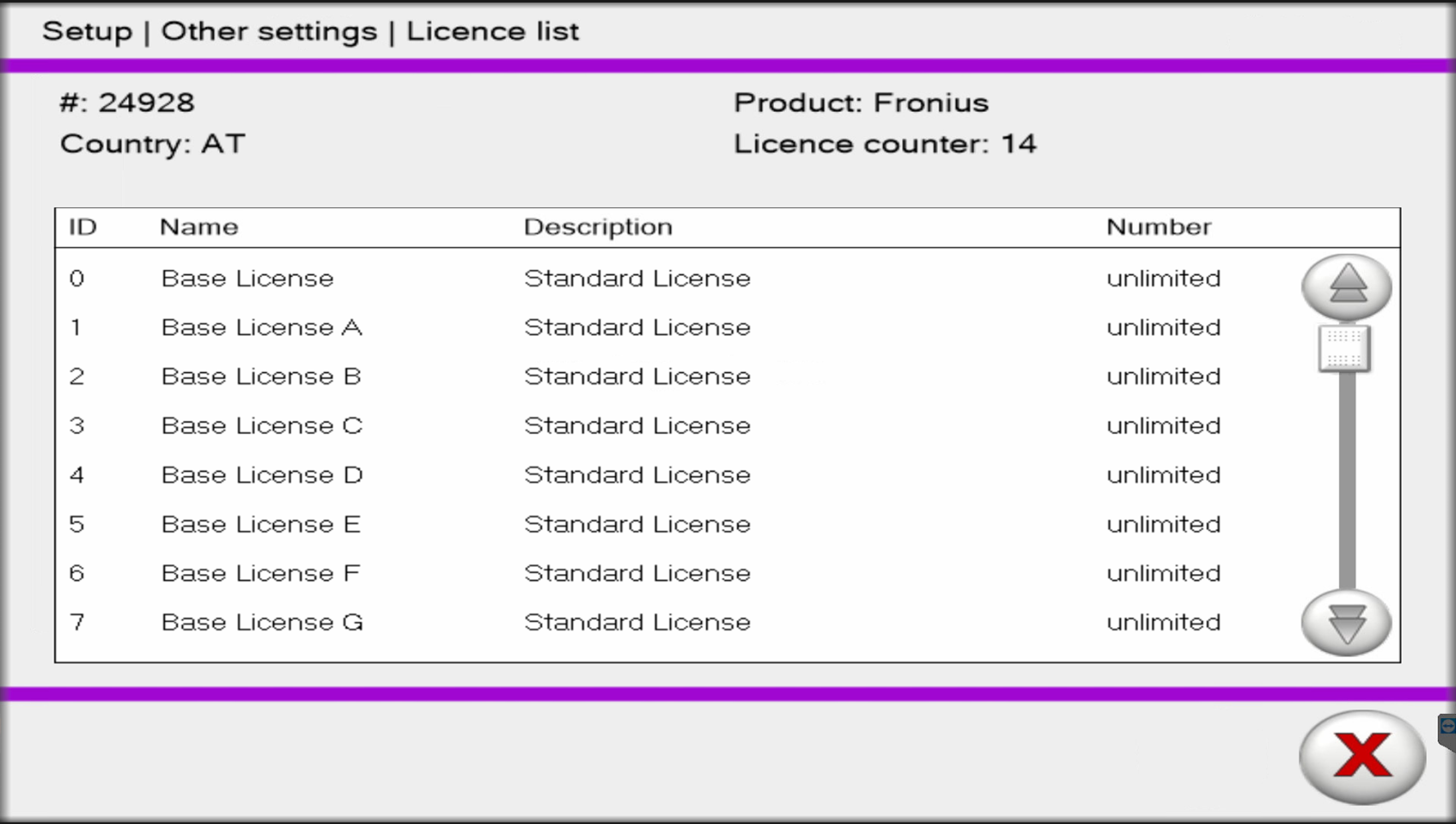
License list
Displaying the license list
The license list contains the licenses currently available on the Virtual Welding system, including additional information (such as license name, description, etc).
1Enter the Setup menu - see Accessing the Setup menu on page (→)
2Select button (1)
- The license list is displayed
License list
Creating a backup (exporting data)
- The export function can be used to store Virtual Welding system data on a USB thumb drive, for example to back up data.
- It is recommended to back up the Virtual Welding system data once a week.
To export data:

1Connect a USB thumb drive to the USB port of the Virtual Welding system
2Enter the Setup menu - see Accessing the Setup menu on page (→)
3Select button (1)

4Select button (2) to export all data. These include:
- Courses
- Curricula
- Profiles
- Ranking lists (without Playbacks)
- Settings for the variable Ghost
4Select button (3) to export only the variable Ghost settings
- The button can only be selected if a variable Ghost has been created

5Select button (4) to start data export
6Disconnect the USB thumb drive from the Virtual Welding system
Management code
This section describes how to change the default management code (1234).
NOTE!
Risk of code loss.
Never forget the code you entered, otherwise you will not be able to make important settings. If the code is lost, contact your dealer.

1Enter the Setup menu - see Accessing the Setup menu on page (→)
2Select button (1)

3Enter the desired management code
4Select button (2)
Language settings
- The Virtual Welding system is available in up to 8 languages
- Of these 8 languages, a maximum of 6 languages can be activated
- The language settings determine which languages are active and can therefore be selected by the user
- One of the active languages must be defined as the default language

1Enter the Setup menu - see Accessing the Setup menu on page (→)
2Select button (1)

To change the language settings:
3In area (2), select the languages to be activated
4Select button (4) to save
To define the default language:
3In area (3), define the desired language as the default
4Select button (4) to save
Importing data (only available to administrators)
Selected Virtual Welding system settings can be imported from a USB thumb drive.
Risk of data loss: Importing will overwrite the settings stored on the system.
To import data:

1Connect a USB thumb drive to the USB port of the Virtual Welding system
2Enter the Setup menu - see Accessing the Setup menu on page (→)
3Select button (1)

4Select button (2) to import all data. These include:
- Courses
- Curricula
- Profiles
- Ranking lists (without Playbacks)
- Settings for the variable Ghost
4Select button (3) to import only the variable Ghost settings
- Button (3) can only be selected if the corresponding data are available

5Select the content to import, for example (4) and (5)
6Select button (6) to start the data import
Displaying / changing country profiles (only available for administrators)
Several country profiles can be selected in some country versions of the Virtual Welding software. These country profiles can affect the availability of Virtual Welding software functions.
To display / change country profiles:

1Enter the Setup menu - see Accessing the Setup menu on page (→)
2Select button (1)

3Select the desired country profile, for example (2)
4Select button (3) to save
Restoring factory settings (only available for administrators)
NOTE!
Risk of data loss.
Restoring the factory defaults resets all settings in the Setup menu to factory defaults. Settings that have been made are lost, such as network settings, curricula, courses, ranking lists, etc.

1Enter the Setup menu - see Accessing the Setup menu on page (→)
2Select button (1)

3Press button (2) to restore factory settings
Performing sensor registration (only available for administrators)
- NFC keys are supplied with each Virtual Welding system, which are used to enter terminal management or the Setup menu
- When starting for the first time, it is possible to create an administrator or a user using an NFC key
- The administrator has access to the full range of functions
- The user has a reduced menu structure and fewer settings
- To ensure that the Virtual Welding system is fully functional, at least one NFC key for administrators must be registered
- Registering more NFC keys is possible for both administrators and users at any time

1Enter the Setup menu - see Accessing the Setup menu on page (→)
2Select button (1)

To register the NFC key for administrators:
3Keep the NFC key in question ready
4In area (2), select the administrator button
5When prompted on the touch screen, pass the NFC key over the sensor
6Confirm the message that now appears
To register the NFC key for users:
3Keep the NFC key in question ready
4In area (2), select the user button
5When prompted on the touch screen, pass the NFC key over the sensor
6Confirm the message that now appears
To remove the NFC key for administrators:
3Keep the NFC key in question ready
4In area (3), select the administrator button
5When prompted on the touch screen, pass the NFC key over the sensor
6Confirm the message that now appears
To remove the NFC key for users:
3Keep the NFC key in question ready
4In area (3), select the user button
5When prompted on the touch screen, pass the NFC key over the sensor
6Confirm the message that now appears
To remove all NFC keys:
3Keep the NFC key in question ready
4In area (3), select the button for all users
5Now confirm the following security prompt
Technical settings menu item
Setting the date and time (only available for administrators)

1Enter the Setup menu - see Accessing the Setup menu on page (→)
2Select button (1)
3Change the desired data
Setting the date and time (only available for administrators)
1Enter the Setup menu - see Accessing the Setup menu on page (→)
2Select button (1)
3Change the desired data
Displaying the NSB number
The NSB number is the version number of the Virtual Welding software. This number is required for support questions, for example.

1Enter the Setup menu - see Accessing the Setup menu on page (→)
2Select button (1)
- The NSB number is displayed
Test image (only available for administrators)
The test image allows you to check the screen settings.

1Enter the Setup menu - see Accessing the Setup menu on page (→)
2Select button (1)

3Touch anywhere on the touch screen
- After each touch of the touch screen, the next test image is displayed
4When the check is complete, select button (2)
Defining the model

1Enter the Setup menu - see Accessing the Setup menu on page (→)
2Select button (1)
3Select the correct data
4Save the entries
Activating the memory check (only available for administrators)
Select the ScanDisk menu item to identify and correct errors on the hard disk. As a rule, the system will become more efficient again.

1Enter the Setup menu - see Accessing the Setup menu on page (→)
2Select button (1)

3Select checkbox (2)
4Select button (3)
- The next time the Virtual Welding system is restarted, the memory check is performed
NOTE!
As long as the memory check is activated, it is performed each time the Virtual Welding system is restarted.
Performing the touch screen test (only available for administrators)
The touch screen test is used to test the touch screen calibration.

1Enter the Setup menu - see Accessing the Setup menu on page (→)
2Select button (1)

3Touch anywhere on the touch screen
- A square indicates where the touch was registered
4When the test is complete, select button (2)
Setting the volume (only available for administrators)

1Enter the Setup menu - see Accessing the Setup menu on page (→)
2Select button (1)

3Make the desired settings
4Select button (2)
Troubleshooting, maintenance, and disposal
Troubleshooting
General
- Errors occur that are not covered in this document, or
- The troubleshooting measures provided in this document are unsuccessful.
Troubleshooting
General
- Errors occur that are not covered in this document, or
- The troubleshooting measures provided in this document are unsuccessful.
General
- Errors occur that are not covered in this document, or
- The troubleshooting measures provided in this document are unsuccessful.
Safety
WARNING!
Danger from incorrect operation and work that is not carried out properly
This can result in severe personal injury and damage to property.
Only trained personnel are permitted to perform the work and functions described in this document, in accordance with the applicable national and international standards.
Read and understand this document.
Read and understand all the Operating Instructions for the system components, especially the safety rules.
WARNING!
Danger from electrical current
This may result in serious injuries or death.
Before starting work, switch off all the devices and components involved and disconnect them from the grid.
Secure all devices and components involved so they cannot be switched back on.
After opening the device, use a suitable measuring instrument to check that electrically charged components (such as capacitors) have been discharged.
WARNING!
Danger of electrical shock due to inadequate ground conductor connection
This can result in severe personal injury and damage to property.
The housing screws provide a suitable ground conductor connection for grounding the housing. Replacing the housing screws with other screws without a reliable protective conductor connection is prohibited.
Always use the original housing screws in the quantity initially supplied.
Observe the correct torque when tightening the housing screws.
Troubleshooting
The device is not working
The power switch is on, the touch screen remains dark, the device fan remains still
| Cause: | The mains lead is disconnected, the mains plug is not plugged in |
| Remedy: | Check the mains lead and insert the mains plug if necessary |
| Cause: | The mains socket or mains plug is defective |
| Remedy: | Replace the defective parts |
| Cause: | The mains fuse has tripped |
| Remedy: | Remove the cause of the mains fuse tripping and restore the mains fuse |
Welding torch / electrode holder positioning is different from that shown in the 3D glasses
| Cause: | Incorrect calibration of individual components |
| Remedy: | First step: press the Fronius logo for 3 seconds - this starts component calibration. For more information on component calibration, see section Component calibration from page (→) Second step: perform system calibration - see section System calibration from page (→) |
The positioning of the welding torch/electrode holder deviates from what is shown on the touch screen
| Cause: | The welding torch or electrode holder is incorrectly calibrated |
| Remedy: | Perform system calibration - see section System calibration from page (→) |
The 3D visualization shakes
| Cause: | Another Virtual Welding system is located in the immediate vicinity |
| Remedy: | Increase the distance to the other Virtual Welding system to at least 4 m (157.48 inches) |
| Cause: | Devices that emit radiation (such as cell phones, etc.) are located in the immediate vicinity of the Virtual Welding system |
| Remedy: | Remove devices |
| Cause: | Metallic objects are located in the immediate vicinity of the Virtual Welding system |
| Remedy: | Remove objects |
The 3D visualization appears incorrectly on the touch screen
The movement of the welding torch or electrode holder and/or the 3D glasses is not displayed, uncoordinated 3D visualization on the touch screen
| Cause: | The welding torch/electrode holder is not connected |
| Remedy: | Connect the welding torch/electrode holder |
| Cause: | 3D glasses are not connected |
| Remedy: | Connect the 3D glasses |
| Cause: | The workpiece holder is not connected |
| Remedy: | Connect the workpiece holder |
| Cause: | Sensor cable or sensor plug of welding torch/electrode holder is defective |
| Remedy: | Replace the sensor cable |
| Cause: | The workpiece is not adequately engaged within the workpiece holder |
| Remedy: | Engage the workpiece properly in the workpiece holder |
The 3D visualization only works for rotations, not for forward and backward movements
| Cause: | The 3D glasses cannot detect the surrounding room |
| Remedy: | Make sure that the cameras of the 3D glasses are clean and not covered (by hair, caps, hands, etc.) |
| Cause: | Incorrect room calibration |
| Remedy: | Perform room calibration - see section Room calibration from page (→) |
The image in the 3D glasses gives the impression that you are standing far above or below the workpiece; forward and backward movements and head rotations are correctly displayed
| Cause: | Faulty component calibration |
| Remedy: | press the Fronius logo for 3 seconds - this starts component calibration. For more information on component calibration, see section Component calibration from page (→) |
The 3D glasses do not work
| Cause: | The 3D glasses are not connected to the Virtual Welding system |
| Remedy: | Connect the 3D glasses data cable to the Virtual Welding system |
| Cause: | The 3D glasses were connected after switching on the Virtual Welding system |
| Remedy: | Turn off the Virtual Welding system; connect the 3D glasses; turn on the Virtual Welding system |
| Cause: | The 3D glasses are defective |
| Remedy: | Replace the 3D glasses |
| Cause: | The 3D glasses are not being supplied with power |
| Remedy: | Plug in the power supply of the 3D glasses |
The buttons on the welding torch do not work
| Cause: | The welding torch is not connected |
| Remedy: | Connect the welding torch |
Maintenance and disposal
General
The device only requires a minimum of service and maintenance under normal operating conditions. However, several points must be observed in order for the device to remain operational for years to come.
General
The device only requires a minimum of service and maintenance under normal operating conditions. However, several points must be observed in order for the device to remain operational for years to come.
Safety
WARNING!
Danger from incorrect operation and work that is not carried out properly
This can result in severe personal injury and damage to property.
Only trained personnel are permitted to perform the work and functions described in this document, in accordance with the applicable national and international standards.
Read and understand this document.
Read and understand all the Operating Instructions for the system components, especially the safety rules.
WARNING!
Danger from electrical current
This may result in serious injuries or death.
Before starting work, switch off all the devices and components involved and disconnect them from the grid.
Secure all devices and components involved so they cannot be switched back on.
After opening the device, use a suitable measuring instrument to check that electrically charged components (such as capacitors) have been discharged.
WARNING!
Danger of electrical shock due to inadequate ground conductor connection
This can result in severe personal injury and damage to property.
The housing screws provide a suitable ground conductor connection for grounding the housing. Replacing the housing screws with other screws without a reliable protective conductor connection is prohibited.
Always use the original housing screws in the quantity initially supplied.
Observe the correct torque when tightening the housing screws.
Maintenance at every start-up
- Check all components, including the mains plug, mains cable, and cables of the system components for damage and replace any damaged components
- Check that the ventilation openings are not covered, not even partially
Disposal
Materials should be disposed of according to valid local and national regulations.
Update
Installing the Update
Preparation for the update
To prepare the Virtual Welding system for the update:
1Disconnect the 3D glasses
2Back up data - see section Creating a backup (exporting data) from page (→)
3Connect a keyboard to the Virtual Welding system
To configure the USB thumb drive for the update:
4Download the update folder to a PC
- The update folder can be found at www.virtualwelding.com
5Unzip the update folder
6Connect a boot-capable USB thumb drive to the PC
7Open the .exe file in the update folder

8If necessary, use button (1) to change the language of the program
9Use button (2) to select the boot-capable USB thumb drive that has already been connected to the PC

10Use button (3) to select the „.iso“ file that is located in the update folder

11Select „GPT“ with button (4)

12Select „UEFI“ or "BIOS" with button (5)
- Depending on the system, one of the two options is available

13Enter „VWUPDATE“ in field (6)

14Select „Large FAT32 (Default)“ with button (7); select "32 kilobites (default)" with button (8)

15Select Checkbox (9) and (10)

16Select button (11)

By selecting button (12), all existing data on the USB thumb drive are deleted and all data required for the update are saved on the USB thumb drive.
17Select button (12)

Once the load bar (13) is completely green, the USB thumb drive is configured and can be used to update the Virtual Welding system
Installing the Update
Preparation for the update
To prepare the Virtual Welding system for the update:
1Disconnect the 3D glasses
2Back up data - see section Creating a backup (exporting data) from page (→)
3Connect a keyboard to the Virtual Welding system
To configure the USB thumb drive for the update:
4Download the update folder to a PC
- The update folder can be found at www.virtualwelding.com
5Unzip the update folder
6Connect a boot-capable USB thumb drive to the PC
7Open the .exe file in the update folder
8If necessary, use button (1) to change the language of the program
9Use button (2) to select the boot-capable USB thumb drive that has already been connected to the PC
10Use button (3) to select the „.iso“ file that is located in the update folder
11Select „GPT“ with button (4)
12Select „UEFI“ or "BIOS" with button (5)
- Depending on the system, one of the two options is available
13Enter „VWUPDATE“ in field (6)
14Select „Large FAT32 (Default)“ with button (7); select "32 kilobites (default)" with button (8)
15Select Checkbox (9) and (10)
16Select button (11)
By selecting button (12), all existing data on the USB thumb drive are deleted and all data required for the update are saved on the USB thumb drive.
17Select button (12)
Once the load bar (13) is completely green, the USB thumb drive is configured and can be used to update the Virtual Welding system
Performing the update
1Switch the power switch of the Virtual Welding system to the - O - position
2Connect the USB thumb drive to the USB port of the Virtual Welding system
3Switch the power switch of the Virtual Welding system to the - I - position
- „elo“ is displayed on the Touchscreen
4While „elo“ is displayed on the Touchscreen, press and hold the "Remove" key on the keyboard
- This will open the BIOS menu
- If the BIOS menu does not open, repeat the above steps

BIOS menu

5Use the arrow keys on the keyboard to select the "Save & Exit" menu item (1)

6Under the „Boot Override“ menu item, select the USB thumb drive containing the update data (2)
- The USB thumb drive is always marked with „Flash Drive“ or „Flash Disk“
- If the USB thumb drive is not displayed, the USB thumb drive has not been detected. In this case:
- Switch the power switch of the Virtual Welding system to the -O- position, disconnect and re-prepare the USB thumb drive (see section Preparation for the update from page (→))
7After selecting the USB thumb drive, press „Enter“ to start the update

Once the touch screen displays „Press any key to continue...“ in a black window (3), the update has been successfully completed
8Press any key on the keyboard
- The Virtual Welding system shuts down automatically
9Switch the Virtual Welding system power switch to the -O- position
10Disconnect the keyboard and USB thumb drive from the Virtual Welding system
- The Virtual Welding system is ready for operation
Technical data
Technical data
Special voltage
For devices designed for special voltages, the technical data on the rating plate applies.
Technical data
Special voltage
For devices designed for special voltages, the technical data on the rating plate applies.
Special voltage
For devices designed for special voltages, the technical data on the rating plate applies.
StandUp Terminal, MobileCase
Mains voltage +/- 10% | 110 V – 230 V |
Grid frequency | 50 / 60 Hz |
Mains fuse protection | 2 x 3.15 A slow-blow |
Current consumption | Max. 1.2 A |
EMC device class | A |
Marks of conformity | CE |
Standards
The device has been tested according to the following standards in line with the applicable guidelines and compliance with these has been determined.
EN 55032:2015 | In accordance with 2014/30/EU and 2014/35/EU |
EN 55024:2010 + A1:2015 | |
EN 61000-3-2:2014 | |
EN 61000-3-3:2013 | |
EN 62368-1:2014 + A11:2017 / | |
EN 62311:2008 |