- Operating instructionsFronius Datamanager 2.0
- General information
- Installing Fronius Datamanager 2.0
- Establishing a Connection to Fronius Datamanager 2.0
- Current Data, Services, and Settings on Fronius Datamanager 2.0
- The Fronius Datamanager 2.0 Website
- Current Data in Fronius Datamanager 2.0
- Services – System Information
- Services – Network Diagnostics
- Services – Firmware Update
- Services – Opening Wizards
- Settings – General
- Settings – Passwords
- Settings – Network
- Settings – Fronius Solar.web
- Settings - IO Mapping
- Settings - load management
- Settings – Push Service
- Modbus Settings
- Settings – Inverter
- Settings – Fronius Sensor Cards
- Settings – Counter
- Settings – DNO Editor
- General
- UC Editor – IO control
- Connection diagram - 4 relays
- Connection diagram - 3 relays
- Connection diagram - 1 relay
- Connection diagram - alternative with 2 relays
- Example of application with two ripple control receivers
- Connecting ripple control receiver to several inverters
- UC Editor—AUS—Demand Response Modes (DRM)
- UC Editor – dynamic power reduction
- Dynamic feed-in limit with multiple inverters
- UC Editor – Control priorities
032-02032026
General information
General
General
The Fronius Datamanager 2.0 is a network-compatible datalogger which combines the functionality of the Fronius Com Card, the Fronius Datalogger Web, the Fronius Power Control Card, and the Fronius Modbus Card on one plug-in card.
The Fronius Datamanager 2.0 website provides a quick overview of the photovoltaic system.
The website can be accessed with a web browser via a direct connection or on the internet, if properly configured.
When connected to Fronius Solar.web, the real-time and archived data of a photovoltaic system can be easily accessed via the internet or the Fronius Solar.web app. No difficult configuration is required. Data is sent automatically from the Fronius Datamanager 2.0 to Fronius Solar.web. Fronius Solar.web is equipped with an easy-to-configure system monitoring feature with an automatic alarm. The alarm can be signaled via SMS or e-mail.
General
General
The Fronius Datamanager 2.0 is a network-compatible datalogger which combines the functionality of the Fronius Com Card, the Fronius Datalogger Web, the Fronius Power Control Card, and the Fronius Modbus Card on one plug-in card.
The Fronius Datamanager 2.0 website provides a quick overview of the photovoltaic system.
The website can be accessed with a web browser via a direct connection or on the internet, if properly configured.
When connected to Fronius Solar.web, the real-time and archived data of a photovoltaic system can be easily accessed via the internet or the Fronius Solar.web app. No difficult configuration is required. Data is sent automatically from the Fronius Datamanager 2.0 to Fronius Solar.web. Fronius Solar.web is equipped with an easy-to-configure system monitoring feature with an automatic alarm. The alarm can be signaled via SMS or e-mail.
General
The Fronius Datamanager 2.0 is a network-compatible datalogger which combines the functionality of the Fronius Com Card, the Fronius Datalogger Web, the Fronius Power Control Card, and the Fronius Modbus Card on one plug-in card.
The Fronius Datamanager 2.0 website provides a quick overview of the photovoltaic system.
The website can be accessed with a web browser via a direct connection or on the internet, if properly configured.
When connected to Fronius Solar.web, the real-time and archived data of a photovoltaic system can be easily accessed via the internet or the Fronius Solar.web app. No difficult configuration is required. Data is sent automatically from the Fronius Datamanager 2.0 to Fronius Solar.web. Fronius Solar.web is equipped with an easy-to-configure system monitoring feature with an automatic alarm. The alarm can be signaled via SMS or e-mail.
Territorial Limitations
This product is intended for use and sale outside the Province of Québec. It does not meet the French language documentation and labeling requirements of Québec's Charter of the French Language. Accordingly, Fronius Internation GmbH does not offer this product for sale to, or for delivery to, any address within the Province of Québec.
By placing an order, the customer represents and warrants that they are not purchasing the product for use or resale within Québec. Fronius International GmbH disclaims all liability and warranty obligations for any products operated in Québec in violation of these restrictions.
Data security
- Backing up any changes made to the factory settings
- Saving and storing personal settings
NOTE!
Data security for network and Internet connection
Unsecured networks and a lack of safeguards can result in data loss and unauthorized access. Observe the following points for safe operation:
Operate inverters and system components on a private, secure network.
Keep the network devices (e.g., WiFi routers) up to date with the latest technology.
Keep the software and/or firmware updated.
Use a wired network to ensure a stable data connection.
For security reasons, do not make inverters and system components accessible from the Internet via port forwarding or Port Address Translation (PAT).
Use the solutions provided by Fronius for monitoring and remote configuration.
The optional communication protocol Modbus TCP/IP1) is an unsecured interface. Only use Modbus TCP/IP if no other secured data communication protocol (MQTT2)) is possible (e.g., compatibility with older Smart Meters).
1) TCP/IP - Transmission Control Protocol/Internet Protocol
2) MQTT - Message Queuing Telemetry Protocol
Available versions of the Fronius Datamanager 2.0
- Without Fronius Com Card function
(for Fronius Galvo Fronius Symo, and Fronius Primo inverters) - With Fronius Com Card function
(for Fronius IG, Fronius IG Plus, Fronius IG Plus V,
Fronius IG Plus A, Fronius CL, Fronius CL USA, Fronius IG 300–500 inverters) - In external housing with Fronius Solar Net IN and Fronius Solar Net OUT connection sockets
(Fronius Datamanager Box 2.0, e.g., for inverters without plug-in card slots or for photovoltaic systems with a separate Fronius Datamanager 2.0)
Provided that the inverter is not fitted as standard with the Fronius Datamanager 2.0, existing inverters can be upgraded with the Fronius Datamanager 2.0 plug-in card.
Applicable DATCOM Components
The Fronius Datamanager 2.0 plug-in card installed in the inverter or the separate Fronius Datamanager Box 2.0 can be operated with the following DATCOM components:
- up to 100 | x | Fronius inverters |
- up to 10 | x | Fronius Sensor Card or Fronius Sensor Box |
- up to 10 | x | Fronius Public Display Card or Fronius Public Display Box |
- up to 1 | x | Fronius Interface Card or Fronius Interface Box |
- up to 200 | x | Fronius String Control |
Prerequisites for operation
- For cabled internet solutions, Fronius recommends a download speed of at least 512 kbit/s and an upload speed of
at least 256 kbit/s. - For solutions with mobile internet services, Fronius recommends a minimum transmission standard of 3G with reliable signal strength.
These specifications do not provide an absolute guarantee of flawless operation.
High error rates in the transmission, reception fluctuations, or connection dropouts can have an adverse effect on Fronius Datamanager 2.0's online operation.
Fronius recommends on-site testing to ensure that the connections meet the minimum requirements.
If you want to connect your inverter(s) to the internet using WLAN, we recommend the following approach:
- Test your signal strength in the exact position where the inverter is to be installed and make sure the Datamanager 2.0 card is activated.
- Connect to the WLAN network using a smartphone, laptop, or tablet, and test the connection.
The free website "www.speedtest.net" can be used to check whether the connection meets our recommended download speed of at least 512 kbit/s and an upload speed of 256 kbit/s.
Since the Fronius Datamanager 2.0 acts as a datalogger, no other datalogger may be present in the Fronius Solar Net ring.
There must only be one Fronius Datamanager 2.0 for each Fronius Solar Net ring.
The Fronius Datamanager 2.0 must be in secondary mode if installed in Fronius Galvo and Fronius Symo inverters.
- Fronius Power Control Card/Box
- Fronius Modbus Card
- Fronius Datalogger Web
- Fronius Personal Display DL Box
- Fronius Datalogger easy/pro
- Fronius Datamanager
- Fronius Datamanager 2.0 Box
- the plug-in card must be installed in an inverter,
or - there must be a Fronius Datamanager Box 2.0 in the Fronius Solar Net ring.
The Fronius Datamanager 2.0 plug-in card and the Fronius Com Card must not be used together in one inverter.
Inverter software required
Fronius Datamanager 2.0 requires the following inverter software versions for its operation:
Inverter |
| required software version according to display |
|---|---|---|
Fronius IG 15–60 |
| V2.9.4 or higher |
Fronius IG 2000–5100 |
| starting from series no 19153444 |
Fronius IG 300–500 |
| V3.6.4.0 or higher |
Fronius IG Plus 35–150 |
| V4.22.00 or higher |
Fronius IG TL * |
| - |
Fronius CL |
| V4.22.00 or higher |
Fronius Agilo * |
| - |
Fronius Agilo Outdoor * |
| - |
Fronius Agilo TL * |
| - |
Fronius Galvo |
| - |
Fronius Symo |
| - |
Fronius Symo Hybrid |
| - |
Fronius Primo |
| - |
Fronius Eco |
| - |
|
|
|
| * | Only in conjunction with Fronius Datamanager Box 2.0 |
The relevant inverter software version can be downloaded for free from our homepage (http://www.fronius.com).
If you have any questions, please contact pv-support@fronius.com.
Notes regarding radio certification
The Fronius Datamanager 2.0 plug-in card and Fronius Datamanager Box 2.0 are equipped with a wireless module.
Wireless modules in the USA require FCC certification:
 | FCC This device conforms to the limit values for a Class B digital device, pursuant to Part 15 of the FCC regulations. These limits are designed to provide reasonable protection against harmful interference in a residential installation. This device generates and uses high frequency energy and, if not used in accordance with the instructions, may interfere with radio communications. However, there is no guarantee that interference will not occur in a particular installation.
FCC ID: PV7-WIBEAR11N-DF1 |
Industry Canada RSS This device complies with Industry Canada license-exempt RSS standards. Operation is subject to the following two conditions: IC ID: 7738A-WB11NDF1 |
Unless otherwise expressly permitted by the manufacturer, changes or modifications to the wireless module are not allowed and lead to a loss of the right of use of the device by the user.
Scope of Supply
Fronius Datamanager 2.0 plug-in card
- 1 x Fronius Datamanager 2.0 plug-in card
- 1 x Fronius Solar Net termination plug
- 1 x 16-pin plug
- 1 x FCC sticker label, three parts
Additional equipment depending on the inverter:
|
| Fronius Galvo |
|
| Fronius IG |
|
| Fronius IG 300 - 500 |
|
| Fronius IG 2000 - 5100 - USA |
Fronius Datamanager Box 2.0
- 1 x Fronius Datamanager Box 2.0 with wall bracket
- 2 x Fronius Solar Net termination plugs
- 1 x 16-pin plug
- 1 x antenna
- 1 x 3 m RG58 antenna cable
- 1 x mounting bracket
- 1 x double-sided adhesive tape
- 2 x installation anchors + screws
- 1 x "DATCOM Cabling" leaflet
Using the Sticker Labels
IMPORTANT! If the three-part sticker label included in the scope of supply for the Datamanager 2.0 has not already been affixed to the inverter at the factory, this must be done now.
Position of the sticker label on the inverter:


For Fronius Galvo, Fronius Symo, and Fronius Primo inverters, the sticker label information is located on the rating plate.
Using the sticker labels:

| (1) | On the cardboard packaging of the inverter or the Fronius Datamanager 2.0 |
| (2) | On the Fronius Datamanager 2.0 plug-in card |
| (3) | On the inverter |
Configuration Examples
Linking Inverters with a Fronius Datamanager 2.0 Plug-in Card to a PC: | ||||||||||
 |
|
| ||||||||
IMPORTANT!When linking an inverter with Fronius Datamanager 2.0 to a PC, one Fronius Solar Net termination plug must be connected at each free IN or OUT connection.
Linking Inverters with a Fronius Datamanager 2.0 Plug-in Card to Other Inverters, a Fronius Sensor Box, and a PC: | ||||||||||||||||||||
 | ||||||||||||||||||||
|
|
| ||||||||||||||||||
When linking several DATCOM components to Fronius Datamanager 2.0:
Use the data cable to connect the IN connection socket of Fronius Datamanager 2.0 with the OUT connection socket of the next DATCOM component. A Fronius Solar Net termination plug must be inserted into the empty IN connection socket of the last DATCOM component.
With the following inverters, the inverter with Fronius Datamanager 2.0 must always be connected either at the start or end of the data chain:
Fronius IG, Fronius IG Plus, Fronius IG Plus V, Fronius IG Plus A, Fronius CL, Fronius CL USA and Fronius IG 300–500.
Linking Two Inverters with Fronius Com Card or Com Card Function to a Fronius Datamanager Box 2.0 and a Smartphone: | ||||||||||||
 | ||||||||||||
|
|
| ||||||||||
When linking several DATCOM components with a Fronius Datamanager Box 2.0, each of the DATCOM components must be cabled from the IN connection socket to the OUT connection socket of the next DATCOM component.
Fronius Solar Net termination plugs must be inserted into empty IN or OUT connection sockets of the last DATCOM components.
Calculating the data volume
General
When operating Fronius Datamanager 2.0, data are generated and need to be transmitted via the internet.
In order to select a suitable internet connection, it is necessary to calculate the data volume.
General
When operating Fronius Datamanager 2.0, data are generated and need to be transmitted via the internet.
In order to select a suitable internet connection, it is necessary to calculate the data volume.
Calculating data volumes
The following information is used to calculate the data volume per month when operating the Fronius Datamanager 2.0.
Hourly upload | Up to firmware version 3.17 | From firmware version 3.25.2 upwards |
|---|---|---|
Total | 8 MB | 350 MB |
+ for each additional Fronius inverter | 5 MB | |
+ for each additional Fronius Smart Meter | 7 MB | |
Daily/weekly upload | Up to firmware version 3.17 | From firmware version 3.25.2 upwards |
|---|---|---|
Total | 307 kB | 350 MB |
+ for each additional Fronius inverter | 520 kB | |
+ for each additional Fronius Smart Meter | 769 kB | |
Daily/weekly upload | Up to firmware version 3.17 | From firmware version 3.25.2 upwards |
|---|---|---|
Total | 100 kB | 350 MB |
+ for each additional Fronius inverter | 520 kB | |
+ for each additional Fronius Smart Meter | 769 kB | |
Calculation of memory sectors per day according to chapter "Calculating memory capacity" on page (→).
The data volume may increase due to the following factors:- Disconnections
- Restarting the inverter
- Firmware updates
- Remote control (VPP, Cloud Control)
- Fault diagnosis by technical support
- Remote system monitoring via Fronius Solar.web
IMPORTANT! Fronius recommends a flat rate to avoid costs for data volumes that were not taken into account in the preliminary calculation.
General information for the network administrator
Requirements
Configuring a network for Fronius Datamanager 2.0 requires knowledge of network technology.
If Fronius Datamanager 2.0 is being integrated into an existing network, the Fronius Datamanager 2.0 address must be adapted to the network.
Example: network address range = 192.168.1.x, subnet mask = 255.255.255.0
- An IP address between 192.168.1.1 and 192.168.1.254 must be assigned to Fronius Datamanager 2.0.
- The IP address selected may not be already assigned in the network.
- The subnet mask must correspond to the existing network (e.g., 255.255.255.0).
If Fronius Datamanager 2.0 will be sending service messages and/or data to Fronius Solar.web, then a gateway address and a DNS server address must also be entered. Fronius Datamanager 2.0 uses the gateway address to access the internet. The IP address of the DSL router can be used as a gateway address, for example.
IMPORTANT!
- Fronius Datamanager 2.0 may not have the same IP address as the PC/laptop!
- Fronius Datamanager 2.0 cannot connect itself to the internet. A router must be used for a DSL connection to the internet.
General Firewall Settings
DSL routers mostly enable you to send data to the internet and, therefore, do not normally have to be configured.
Server addresses for data transferIf a firewall is used for outgoing connections, the following protocols, server addresses and ports must be allowed for successful data transfer:
- Tcp fronius-se-iot-dm-1.azure.devices.net:8883
- Tcp fronius-se-iot-dm-1.azure.devices.net:443
- Tcp fronius-se-iot-dm-2.azure.devices.net:8883
- Tcp fronius-se-iot-dm-2.azure.devices.net:443
- Tcp fronius-se-iot-dm-1.telemetry.azure.devices.net:8883
- Tcp fronius-se-iot-dm-1.telemetry.azure.devices.net:443
- Tcp fronius-se-iot-dm-2.telemetry.azure.devices.net:8883
- Tcp fronius-se-iot-dm-2.telemetry.azure.devices.net:443
- Fdmp-solarweb.com:49049 (dm local port 54321)
- Tcp http://www3.fronius.com:80
- Tcp http://firmware-download.fronius.com:80
- Tcp ftp://transfer.fronius.com:21
- Tcp provisioning-lite.solarweb.com:443
- Tcp froniusseiot.blob.core.windows.net:443
- Upd/Tcp 0.time.fronius.com:123
If existing firewall rules block the connection to the Fronius system monitoring, the following firewall rules must be added:
| 49049/UDP | 80/TCP *) |
Sending service messages | x | - |
Connecting to Datamanager via Fronius Solar.web | x | - |
Connecting to Datamanager via Fronius Solar.access or Fronius Solar.Service | - | x |
Accessing the Datamanager website | - | x |
Configure the firewall so that the IP address of Fronius system monitoring can send data to port 49049/UDP from “fdmp.solarweb.com”.
*) We recommend only allowing access to the web interface of the Fronius system monitoring from a secure network. If access via the internet is absolutely necessary (e.g. for service purposes during a limited time period), configure the network router so that requests for any external port are redirected to port 80/TCP.
Caution - this will make the inverter visible on the internet and more likely to be subject to network attacks.
Sending Service Messages via a DSL Internet Connection
Normally, no additional router configuration is required for a regular DSL internet connection to access Fronius Solar.web and/or send service messages, because connections from the LAN to the internet are open.
Using Fronius Solar.web and Sending Service Messages
However, an internet connection is required to use Fronius Solar.web and send service messages.
Fronius Datamanager 2.0 cannot connect itself to the internet. A router must be used for a DSL connection to the internet.
Controls, connections and indicators
Safety
WARNING!
Danger due to incorrect operation.
This can result in severe personal injury and damage to property.
Do not use the functions described here until you have fully read and understood the Operating Instructions.
Do not use the functions described here until you have fully read and understood all of the Operating Instructions of the system components, especially the safety rules.
Controls, connections, and indicators

No. | Function |
| |||||
|---|---|---|---|---|---|---|---|
(1) | IP switch |
| |||||
A | Specified IP address and opening the WLAN access point Access data for this access point: IMPORTANT! The Fronius Datamanager 2.0 can be accessed:
|
| |||||
B | Assigned IP address: The Fronius Datamanager 2.0 works with an assigned IP address dynamic host configuration protocol (DHCP) The IP address can be set on the Fronius Datamanager 2.0 website. In the case of the Fronius Datamanager 2.0 plug-in cards, the IP switch is located underneath the LEDs and is separate in the case of the Fronius Datamanager Box 2.0. |
| |||||
(2) | WLAN LED
| 
| |||||
(3) | Solar.web LED connection
| 
| |||||
(4) | Power supply LED
| 
| |||||
(5) | Connection LED
| 
| |||||
(6) | LAN Connection |
| |||||
(7) | I/Os  |
| |||||
Modbus RTU 2-wire (RS485):
| |||||||
Int./ext. power supply
| |||||||
Digital inputs: 0 - 3, 4 - 9 | |||||||
Digital outputs: 0–3 | |||||||
Switching capacity when supplied by an external power supply with min. 12.8 - max. 24 V DC (+ 20%), connected to Uint/Uext and GND: 1 A, 12.8 - 24 V DC (depending on the external power supply) per digital output | |||||||
The connection to the I/Os is made via the supplied mating connector. | |||||||
(8) | Antenna plug |
| |||||
(9) | Modbus termination switch (for Modbus RTU) Switch in "on" position: Termination resistance of 120 Ohm active  IMPORTANT! The termination resistance must be active for the first and last device in an RS485 bus. |
| |||||
(10) | Fronius Solar Net primary/secondary switch |
| |||||
(11) | Fronius Solar Net IN connection socket |
| |||||
(12) | Fronius Solar Net OUT connection socket For the Fronius Datamanager Box 2.0 only! | ||||||
(13) | External power supply connection IMPORTANT! The external power supply unit for the Fronius Datamanager Box 2.0 must be securely disconnected from components supplying grid voltage (SELV or Class 2 for USA/Canada). For the Fronius Datamanager Box 2.0 only! | ||||||
Schematic Connection of I/Os
Supply via the Fronius Datamanager 2.0 plug-in card:

| (1) | Power supply (for Fronius Datamanager 2.0 with Fronius Com Card function only) |
| (2) | Current limit |
| (3) | Solar Net IN connection socket |
115–230 V AC:
Fronius IG, Fronius IG Plus, Fronius IG Plus V, Fronius IG Plus A, Fronius CL, Fronius CL USA, Fronius IG 300 - 500
12.8 V DC:
Fronius Galvo, Fronius Symo, Fronius Primo
Supply via external power supply:

| (4) | External power supply |
| (5) | Load |
| (6) | Switch |
When the supply is via an external power supply, the external power supply must be galvanically isolated.
10.7 V DC:
Fronius IG, Fronius IG Plus, Fronius IG Plus V, Fronius IG Plus A, Fronius CL, Fronius CL USA, Fronius IG 300 - 500
12.8 V DC:
Fronius Galvo, Fronius Symo, Fronius Primo
Technical data
Technical data
Memory capacity | up to 4096 days |
Supply voltage |
|
Energy consumption | < 2 W |
Dimensions |
|
Degree of protection (box) | IP 20 |
External power supply connection (box) | 12 V DC, max. 1 A, Class 2 |
Cable cross section for external power supply connection (box) | 0.13–1.5 mm² |
Ethernet (LAN) | RJ 45, 100 Mbit |
WLAN | IEEE 802.11b/g/n client |
RS 422 (Fronius Solar Net) | RJ 45 |
Ambient temperature |
|
Fronius Solar Net power | approx. 3 W |
I/O connection specifications |
|
Voltage level of digital inputs | low = min. 0 V–max. 1.8 V |
Input currents of digital inputs | depending on the input voltage; |
Switching capacity of digital outputs when supplied by the Fronius Datamanager 2.0 plug-in card | 3.2 W |
Fronius IG, Fronius IG Plus, Fronius IG Plus V, Fronius IG Plus A, Fronius CL, Fronius CL USA, Fronius IG 300–500 | 10.8 V |
Fronius Galvo, Fronius Symo, Fronius Primo | 12.8 V |
Switching capacity of digital outputs when supplied by an external power supply with min. 10.7 – max. 24 VDC | 1 A, 10.7–24 V DC |
Max. switchable inductive loads on the digital outputs | 76 mJ |
Modbus RTU | RS485 2-wire |
Factory setting of RS485 interface: |
|
| * | Given sufficient power supply from Fronius Solar Net, the green LED lights up on every DATCOM component. If the green LED does not light up, the power supply unit available from Fronius should be inserted into the 12 V power supply connection socket of an external DATCOM component. Check the cable and plug connections if necessary. Examples of external DATCOM components: Fronius String Control, Fronius Sensor Box etc. |
Frequency range | 2412 - 2462 MHz |
Channels / power used | Channel: 1-11 b,g,n HT20 |
Modulation | 802.11b: DSSS (1Mbps DBPSK, 2Mbps DQPSK, 5.5/11Mbps CCK) |
Installing Fronius Datamanager 2.0
Inserting Fronius Datamanager 2.0 into an Inverter
General
Please see the Operating Instructions for the respective inverter for information regarding plug-in card installation. Please note the safety and warning information in your inverter's Operating Instructions.
Inserting Fronius Datamanager 2.0 into an Inverter
General
Please see the Operating Instructions for the respective inverter for information regarding plug-in card installation. Please note the safety and warning information in your inverter's Operating Instructions.
General
Please see the Operating Instructions for the respective inverter for information regarding plug-in card installation. Please note the safety and warning information in your inverter's Operating Instructions.
WARNING!
Danger from grid voltage and DC voltage from solar modules.
An electric shock can be fatal.
The connection area should only be opened by an authorized electrician.
The separate power stage set area should only be disconnected from the connection area after first being disconnected from the grid power.
The separate power stage set area should only be opened by Fronius-trained service personnel.
Before making any connections, make sure that the AC and DC sides in front of the inverter are not charged, e.g.:
Switch off the AC automatic circuit breaker for the inverter
Cover solar modules
Please observe the 5 safety rules.
WARNING!
Danger of residual voltage from capacitors.
An electric shock can be fatal.
Wait until the capacitors have discharged.
Follow general ESD guidelines when handling plug-in cards.
Fronius Datamanager 2.0 plug-in positions
The Fronius Datamanager 2.0 plug-in position is specified for each inverter type:
Inverter | Plug-in position |
|---|---|
Fronius IG 15–60 | ENS slot *) |
Fronius IG 300–500 | ENS slot *) |
Fronius IG Plus, | on the far right, unless a ML-MON plug-in card is present |
Fronius CL | on the far right, unless a ML-MON plug-in card is present |
Fronius Galvo | does not matter |
Fronius Symo | does not matter |
Fronius Primo | does not matter |
| *) | If an ENS plug-in card is inserted in the ENS slot: insert the Fronius Datamanager 2.0 in the next slot to the right of the ENS slot. IMPORTANT! The next slot must be kept free. Never remove an existing ENS plug-in card.  |
Installing and connecting WLAN antennas
General
Depending on the inverter the WLAN antenna must be either installed in the inverter or mounted to the outside of the inverter.
IMPORTANT! Always follow the relevant operating instructions when opening an inverter! Observe the safety rules!
General
Depending on the inverter the WLAN antenna must be either installed in the inverter or mounted to the outside of the inverter.
IMPORTANT! Always follow the relevant operating instructions when opening an inverter! Observe the safety rules!
Fronius IG, Fronius IG Plus, Fronius IG Plus V, Fronius CL: Installing and Connecting Antennas

1Use the double-sided adhesive tape to fasten the mounting bracket to the outside of the inverter housing or, if suitable for the antenna cable, secure it in a position near the inverter
IMPORTANT! The double-sided adhesive tape only reaches its maximum bond strength after 24 hours.
IMPORTANT! The mounting bracket may not be screwed to the inverter housing.
It may however be fitted in a nearby position. The relevant screws are not included in the scope of delivery and must be selected by the installer.

2Connect the antenna cable to the antenna socket on the Fronius Datamanager 2.0 plug-in card
3Run the antenna cable out through the DATCOM opening on the inverter
4If possible, secure the cable with a strain relief device
5Close or seal the DATCOM opening in accordance with the inverter operating instructions

6Remove the hex nut and washer from the outside thread of the antenna cable

7Run the antenna cable through the drill hole on the mounting bracket
8Attach the lock washer and screw on the hex nut
9Screw on the antenna
Fronius IG USA, Fronius IG Plus USA, Fronius IG Plus V USA: Installing and Connecting Antennas
1
2
CAUTION!
Danger of short circuit caused by loose metal parts from knockouts.
Loose metal parts in the inverter may cause short circuits when the inverter is powered up. When removing knockouts, make sure that
no loose metal parts fall into the inverter,
any metal pieces that do fall into the inverter are removed immediately.
3
4
NOTE!
In order to ensure leak-tightness, the sealing ring must be fitted to the antenna screw joint before inserting the antenna screw joint into the inverter housing.
5
6
7
8
*Bending radius of the antenna cable: at least 25.4 mm/1 in.
9
10
Installing Fronius Datamanager 2.0 in Fronius Solar Net
Safety
CAUTION!
DATCOM components and/or the PC/laptop may be seriously damaged if the Ethernet or Fronius Solar Net cables are connected incorrectly to the Fronius Datamanager 2.0
The Ethernet cable should only be inserted into the LAN connection socket (colored blue).
The Fronius Solar Net cable should only be inserted into the Fronius Solar Net IN connection socket (colored red).
Installing Inverters with Fronius Datamanager 2.0 in Fronius Solar Net
Fronius IG, Fronius IG Plus, Fronius IG Plus V, Fronius IG Plus A, Fronius CL, Fronius CL USA, Fronius IG 300–500:

Fronius Galvo, Fronius Symo, Fronius Primo:

| * | Fronius Solar Net termination plug, if only one inverter with Fronius Datamanager 2.0 is linked to a PC |
| ** | Fronius Solar Net cable, if an inverter with Fronius Datamanager 2.0 is linked to a PC and other DATCOM components |
| *** | Ethernet cable is not included in the scope of supply for the Fronius Datamanager 2.0/Fronius Datamanager Box 2.0 |
Connection between Fronius Datamanager 2.0 and PC via LAN or WLAN |
1Insert and lay the Ethernet cable in the inverter like a data communication cable in accordance with the operating instructions for the inverter
2Insert the Ethernet cable into the LAN connection socket
3Insert the Ethernet cable into the PC/laptop or into a suitable network connection socket
4If only one inverter with Fronius Datamanager 2.0 is linked to a PC:
Fronius IG, Fronius IG Plus, Fronius IG Plus V, Fronius IG Plus A, Fronius CL, Fronius CL USA, Fronius IG 300 - 500:
Insert the Fronius Solar Net termination plug into the Fronius Solar Net IN connection socket
Fronius Galvo, Fronius Symo, Fronius Primo:
Insert a Fronius Solar Net termination plug into the Solar Net IN connection socket and the Solar Net OUT connection socket
If other DATCOM components are connected to the network, besides the inverter with Fronius Datamanager 2.0:
Insert the Fronius Solar Net cable into the Fronius Solar Net IN connection socket of the Fronius Datamanager 2.0
5Connect the other DATCOM components
IMPORTANT! A Fronius Solar Net termination plug must be inserted into the empty IN connection socket of the last DATCOM component.
IMPORTANT! A Fronius Solar Net termination plug must be inserted into the empty IN connection socket of the last DATCOM component.
Installing Fronius Datamanager Box 2.0 in Fronius Solar Net

| * | Fronius Solar Net termination plug for the last DATCOM component |
| ** | Fronius Solar Net cable, if a Fronius Datamanager Box 2.0 is linked to a PC and other DATCOM components |
| *** | Ethernet cable is not included in the scope of supply for the Fronius Datamanager 2.0/Fronius Datamanager Box 2.0 |
Connection between Fronius Datamanager 2.0 and PC via LAN or WLAN |
1Insert the Ethernet cable into the LAN connection socket
2Insert the Ethernet cable into the PC/laptop or into a suitable network connection socket
3Insert the Fronius Solar Net cable into the Fronius Solar Net OUT connection socket of the Fronius Datamanager Box 2.0
4Insert the Fronius Solar Net cable into the Fronius Solar Net IN connection socket of the inverter as per the inverter operating instructions
5Connect the other DATCOM components
IMPORTANT! A Fronius Solar Net termination plug must be inserted into each empty IN or OUT connection socket of the last DATCOM components.
IMPORTANT! A Fronius Solar Net termination plug must be inserted into each empty IN or OUT connection socket of the last DATCOM components.
Fronius Solar Net Cabling
Fronius Solar Net clients
Inverters with Fronius Datamanager, Fronius Com Card, DATCOM components with external housing, or other DATCOM components will hereinafter be referred to as Fronius Solar Net clients.
Fronius Solar Net clients
Inverters with Fronius Datamanager, Fronius Com Card, DATCOM components with external housing, or other DATCOM components will hereinafter be referred to as Fronius Solar Net clients.
Fronius Solar Net Client Cabling
The data connection for the Fronius Solar Net client is a 1:1 connection using 8-pin data cables and RJ-45 plugs.
The overall line length in a Fronius Solar Net ring must not exceed 1000 m.
Requirements for the Fronius Solar Net data cables
Shielded CAT5 (new) and CAT5e (old) cables compliant with ISO 11801 and EN 50173 must be used for the Fronius Solar Net client cabling. Other cables are not permitted.
IMPORTANT! Do not use ISO/IEC-11801 U/UTP cables!
Permitted cables: | ||
|
|
|
The shield must be crimped onto a CAT5-compatible shielded plug.
Due to the fact that the wires in Ethernet cables are twisted, you must make sure the twisted pairs of wires are assigned correctly for cabling in accordance with TIA/EIA-568B:
Fronius Solar Net contact | Pair no. | Color | ||
|---|---|---|---|---|
1 | +12 V | 3 |  | white/orange line |
2 | GND | 3 |  | orange / white line |
3 | TX+ IN, RX+ OUT | 2 |  | white/green line |
4 | RX+ IN, TX+ OUT | 1 |  | blue / white line |
5 | RX- IN, TX- OUT | 1 |  | white/blue line |
6 | TX- IN, RX- OUT | 2 |  | green/white line |
7 | GND | 4 |  | white/brown line |
8 | +12 V | 4 |  | brown / white line |
- Make sure that the wires are assigned correctly.
- When setting up an independent ground connection (e.g., in patch panels), make sure that the shield is grounded on one side of the cable only.
- EN 50173-1 for Europe
- ISO/IEC 11801:2002 internationally
- TIA/EIA 568 for North America
Rules for use of copper cables apply.
Preassembled data cables
- CAT5 cable 1 m ... 43,0004,2435
- CAT5 cable 20 m ... 43,0004,2434
- CAT5 cable 60 m ... 43,0004,2436
The cables listed above are 8-pin, 1:1 LAN network cables, shielded and twisted, including RJ 45 plugs.
IMPORTANT! Data cables are not UV resistant. They should be protected from sunlight when laid outdoors.
Installing Fronius Datamanager 2.0 – Overview
Safety
WARNING!
Danger due to incorrect operation.
This can result in severe personal injury and damage to property.
Do not use the functions described here until you have fully read and understood the Operating Instructions.
Do not use the functions described here until you have fully read and understood all of the Operating Instructions of the system components, especially the safety rules.
Installing Fronius Datamanager 2.0 requires knowledge of network technology.
Starting for the First Time Using Web Browser
The Fronius Solar.start app makes starting Fronius Datamanager 2.0 for the first time much easier. The Fronius Solar.start app is available from the relevant app store.

- the Fronius Datamanager 2.0 plug-in card must be installed in the inverter,
or - there must be a Fronius Datamanager Box 2.0 in the Fronius Solar Net ring.
IMPORTANT! To establish a connection to Fronius Datamanager 2.0, the end device in question (e.g., laptop, tablet) must be configured as follows:
- "Obtain an IP address automatically (DHCP)" must be activated
WARNING!
Danger from grid voltage and DC voltage from solar modules.
An electric shock can be fatal.
Before opening the inverter, wait until the capacitors have discharged.
Follow the Operating Instructions when opening the inverter.
Observe the safety rules and safety instructions contained in the inverter's Operating Instructions.
1Connect the inverters with Fronius Datamanager 2.0 or Fronius Datamanager Box 2.0 in Fronius Solar Net
IMPORTANT! Inverters Fronius IG, Fronius IG Plus, Fronius IG Plus V, Fronius IG Plus A, Fronius CL, Fronius CL USA, and Fronius IG 300–500 must always be located at the beginning or end of the Fronius Solar Net ring.
IMPORTANT! Inverters Fronius IG, Fronius IG Plus, Fronius IG Plus V, Fronius IG Plus A, Fronius CL, Fronius CL USA, and Fronius IG 300–500 must always be located at the beginning or end of the Fronius Solar Net ring.
2For Fronius Galvo/Fronius Symo/Fronius Primo only and when linking multiple inverters in Fronius Solar Net:
set the Fronius Solar Net primary/secondary switch on the Fronius Datamanager 2.0 plug-in card as required
set the Fronius Solar Net primary/secondary switch on the Fronius Datamanager 2.0 plug-in card as required
- One inverter with Fronius Datamanager 2.0 = primary
- All other inverters with Fronius Datamanager 2.0 = secondary (the LEDs on the Fronius Datamanager 2.0 plug-in cards are off)
3Switch the device to service mode
Inverter with Fronius Datamanager 2.0 plug-in card: orFronius Datamanager Box 2.0:
Inverter with Fronius Datamanager 2.0 plug-in card:
- Switch the IP switch on the Fronius Datamanager 2.0 plug-in card to position A
- Activate the WLAN access point via the Setup menu of the inverter
(the performance of this function depends on the inverter software)
- Switch the IP switch on the Fronius Datamanager Box 2.0 to position A

The inverter/Fronius Datamanager Box 2.0 establishes the WLAN Access Point. The WLAN Access Point stays open for one hour.
4Connect the end device to the WLAN access point
SSID = FRONIUS_240.xxxxx (5–8 digits)
(or connect end device and inverter via Ethernet cable)
SSID = FRONIUS_240.xxxxx (5–8 digits)
- Search for a network with the name "FRONIUS_240.xxxxx"
- Establish a connection to this network
- Enter password from the inverter display
5Enter in the browser:
http://datamanager
or
192.168.250.181 (IP address for WLAN connection)
or
169.254.0.180 (IP address for LAN connection)
http://datamanager
or
192.168.250.181 (IP address for WLAN connection)
or
169.254.0.180 (IP address for LAN connection)
The start page of the Setup wizard appears.

The Technician Wizard is designed for the installer and includes standard-specific settings.
If the Technician Wizard is run, it is essential to note down the assigned service password. This service password is required to configure the Electricity Retailer Editor and Meter menu items.
If the Technician Wizard is not run, no specifications for power reduction are set.
The Solar.web Wizard must be run.
6If necessary, run the Technician Wizard and follow the instructions
7Run the Solar.web Wizard and follow the instructions
The Fronius Solar.web start page appears.
or
The Fronius Datamanager 2.0 website opens.
Establishing a Connection to Fronius Datamanager 2.0
Connecting to Fronius Datamanager 2.0 via a Web Browser
General
The connection to Fronius Datamanager 2.0 via a web browser is suitable for accessing current values with several PC users in a LAN (e.g., company networks, schools).
For example, total and daily yields can be accessed and/or inverter comparisons can be made on the Fronius Datamanager 2.0 website.
Requirements
- At least a LAN or WLAN connection
- Web browser (e.g., Microsoft Internet Explorer IE ≥ 9.0, Firefox 4, Google Chrome 27.0)
- PC/laptop in the same network segment as Fronius Datamanager 2.0
Establishing a Connection to Fronius Datamanager 2.0 via a Web Browser
1Open the web browser
2Enter the IP address or the host name and the domain name for Fronius Datamanager 2.0 in the address field
The Fronius Datamanager 2.0 website opens.
The Fronius Datamanager 2.0 website opens.

Connecting to Fronius Datamanager 2.0 via the Internet and Fronius Solar.web
General
By connecting to Fronius Datamanager 2.0 via the internet and Fronius Solar.web, you can access archived data and up-to-date photovoltaic system data online from anywhere in the world with internet access.
You can also provide other users with guest access so that they can view your photovoltaic system, or you can make a comparison of several systems.
Function Overview
Fronius Datamanager 2.0 is connected to the internet (e.g., via a DSL router). Fronius Datamanager 2.0 regularly logs on to Fronius Solar.web and sends its saved data every day.
Fronius Solar.web can actively contact Fronius Datamanager 2.0, e.g., to display real-time data.
Requirements
- Internet access
- Web browser
IMPORTANT! Fronius Datamanager 2.0 cannot connect itself to the internet. A router must be used for a DSL connection to the internet. - Registration of photovoltaic system with Fronius Solar.web.
- In order to access real-time data in Fronius Solar.web, the "Yes" selection option must be activated under "Send actual data to Fronius Solar.web" in Fronius Datamanager 2.0 in the settings under Solar.web.
- In order to access archived data in Fronius Solar.web, the "Daily at" or "Hourly" selection option must be activated under "Send archive data to Fronius Solar.web" in Fronius Datamanager 2.0.
Accessing Data from Fronius Datamanager 2.0 via the Internet and Fronius Solar.web
To access real-time and archived data from Fronius Datamanager 2.0 using Fronius Solar.web:
1Start Fronius Solar.web: http://www.solarweb.com
For more information about Fronius Solar.web, see the online help.
For more information about Fronius Solar.web, see the online help.
Current Data, Services, and Settings on Fronius Datamanager 2.0
The Fronius Datamanager 2.0 Website
Fronius Datamanager 2.0 Website – Overview
The following data is displayed on the Fronius Datamanager 2.0 website:
(1) | Current comparison view of all inverters in the Fronius Solar Net ring |
(2) | System overview: Current/Day/Year/Total |
(3) | Inverter |
(4) | Sensors |
(5) | Services |
(6) | Contact |
(7) | Settings menu |
(8) | Other setting options |
The setting options on the website of the Fronius Datamanager 2.0 depend on the user's authorization (see section Settings – Passwords on page (→)).
Log in with username and password:
1Select the user to log in.
2Enter the password for the selected user.
3Click the Login button.
The user is logged in.
Reset password
The Forgot your password? function in the login window can be used to reset the password for the selected user.
Request unlock key and save new password:
1Select the user for which you want to reset the password.
2Note the "Challenge" (six-digit number) and Datalogger ID (can be found under the  symbol, see section Other setting options on page (→)).
symbol, see section Other setting options on page (→)).3Contact Fronius Technical Support and provide the "Challenge" and the Datalogger ID.
4Enter the unlock key received from Fronius Technical Support in the Key input field.
5Enter a new password in the Password and Repeat password input fields.
6Click the Save button.
The new password is saved.
The Settings menu
After clicking on "Settings," the Settings menu is opened on the Fronius Datamanager 2.0 website.
Fronius Datamanager 2.0 is configured in the Settings menu.
 Menu items in Settings menu | General adjustment and viewing of menu items 1Establish a connection to Fronius Datamanager 2.0 2Click on Settings 4Click on the desired menu item The desired menu item is opened. 5View menu item or edit accordingly. 6If present, click on the relevant button (e.g., Save, Synchronize) The amended data are applied.
|
Other setting options
Other setting options are shown in the top right corner of the Fronius Datamanager 2.0 website:

| System information: |
 | Help:
|
 | Expand contents: |
 | Display notifications |
 | Language: The Fronius Datamanager 2.0 website will appear in the language set for the browser itself or in the last selected language. |
Current Data in Fronius Datamanager 2.0
Current Comparison View
Several inverters in the same photovoltaic system can be compared in the current Comparison View.
The real-time inverter AC power is displayed as a percentage of the power from the solar module connected to the respective inverter (shown in a bar diagram). A bar is displayed for each inverter. The bar color indicates the power range of the inverter:
Blue: | The inverter power corresponds to the average power of all inverters. |
Yellow: | The inverter power deviates slightly from the average power of all inverters |
Red: | The inverter power deviates significantly from the average power of all inverters or an error has occurred in the inverter |
System Overview
The system overview contains:
- the real-time power data of a photovoltaic system
- the active devices
- the energy generated per day, per year, and in total
- the yield per day, per year, and in total
The values for consumption and energy fed into the grid are only displayed when a meter is configured on the inverter and the meter sends valid data.
Inverter/Sensor View
Inverter View
The Inverter View displays all the inverters present in the system.
Clicking on an inverter or the corresponding bar in the Comparison View displays the inverter's real-time data.
Sensor View
The Sensor View displays all the sensor cards/boxes present in the system.
Services – System Information
System information
The System Information page contains various information about the system.
The following buttons are also available:- Datalogger restart button
Used to restart the datamanager/system monitoring - Reset to factory settings button with the following selection options:
- All settings except for the network
Used to reset the Datamanager (system monitoring) to factory settings.
The network settings and all items protected by the service user (UC Editor, meter settings, and the service password) are retained - All settings
Used to reset the Datamanager (system monitoring) and the network settings to factory settings.
All items protected by the service user (UC Editor, meter settings, and the service password) are retained
- All settings except for the network
IMPORTANT! When the Datamanager (system monitoring) is reset to factory settings, the time and date settings must be checked.
Services – Network Diagnostics
Network diagnostics
The Services / Network diagnostics option contains functions that are useful for diagnosing and correcting network problems. Ping and traceroute commands can be executed.
Ping command
Used to determine whether or not a host is available and how much time a data transfer will take.
Send ping command:
1Enter a host name or IP address in the Host field
2Click on the ping button
- Ping command is sent
- The resulting data is displayed
Traceroute command
Used to determine via which intermediate stations the data reaches the host.
Send traceroute command:
1Enter a host name or IP address in the Host field
2Click on the traceroute button
- Traceroute command is sent
- The resulting data is displayed
Services – Firmware Update
General
You can update the Datamanager firmware under Services/Firmware Update. A firmware update can be performed via LAN or web.
General
You can update the Datamanager firmware under Services/Firmware Update. A firmware update can be performed via LAN or web.
Automatic update search
IMPORTANT! An internet connection is required for the automatic update search.
When the Automatic update search option is activated, the Datamanager will automatically search for updates once a day. If new updates are available, a message is displayed under the other setting options for the website.
Manual update search
When the Automatic update search option is deactivated, there will be no automatic search for updates.
1To search manually for updates, use the Check now button
Firmware update via web
1Open the Datamanager website via a web browser
2Open "Firmware update" under "Services"
3Select Update via Web
4Click on the Run update buttonThe confirmation prompt for the update appears
5Click on the Yes buttonThe update starts and the progress is displayed as a bar and a percentage.
6Once the update has been carried out successfully, click on the Apply/Save  button
button- Deactivate the firewall for the duration of the update
- Retry the update
NOTE!
If a proxy server is used to connect to the internet:
The Use proxy server for Web update option must be activated
The required data must be entered
Firmware update via LAN
1Establish LAN connection between PC/laptop and Datamanager
2Download the current firmware from the Fronius homepage
3Run the downloaded update file on the PC/laptopThis will start a web server from which the Datamanager will download the required files.
4Open the Datamanager website via a web browser
5Open Firmware update under Services
6Select Update via LAN
7Enter the IP address of the PC/laptop
8Click on the Run update buttonThe confirmation prompt for the update appears.
9Click on the Yes buttonThe update starts and the progress is displayed as a bar and a percentage.
10Once the update has been carried out successfully, click on the Apply/Save button
button The update is complete when the supply LED lights up green again.
If the connection to the server fails:- Deactivate the firewall for the duration of the update
- Retry the update
Services – Opening Wizards
Opening wizards
Under Open Wizards, it is possible to re-open the Solar.web Wizard and the Technician Wizard and run these again.
Opening wizards
Under Open Wizards, it is possible to re-open the Solar.web Wizard and the Technician Wizard and run these again.
Settings – General
General
You can enter the charge rate per kWh, the currency, and the expenses per kWh to calculate the yield under "Feed-in payment". The yield is shown in the current Total View.
The date, hour, and minutes can be entered under "System time."
Click on the Synchronize button to adapt the time displayed in the entry fields of the Datamanager website to the time set on the operating system.
Click on the Apply/Save button to apply the time.
The region and location for the time zone can be set under "Time zone settings."
Fields marked with * are mandatory fields.
Settings – Passwords
General
Access to Fronius Datamanager 2.0 is regulated by assigning passwords.
Three different password types are available:
- the administrator password
- the service password
- the user password
General
Access to Fronius Datamanager 2.0 is regulated by assigning passwords.
Three different password types are available:
- the administrator password
- the service password
- the user password
Passwords
Administrator Password
User name = admin
The administrator password set during commissioning assigns the user read and write (configuration) access. The user can then open the Settings menu item and define any settings as desired, with the exception of the UC Editor and Meter.
When an administrator password is set, the user must enter the user name and password to open the "Settings" menu item.
Service Password
User name = service
The service password is usually assigned in the setup wizard by the service technician or system installer and provides access to system-specific parameters. The service password is required to adjust Meter settings and settings in the UC Editor. If no service password has been assigned, the Meter and UC Editor menu items cannot be accessed.
User Password
After activating the Save local site page selection field, the user password is displayed; user name = user.
An assigned user password gives the user read access only. The user cannot open the Settings menu item.
When assigning a user password, users must enter their username and password every time they connect.
Settings – Network
Internet via WLAN

The networks found are displayed.
Clicking on the Refresh button will  perform a new search for available WLAN networks.
Hidden networks can be added via the WLAN Settings > Add WLAN menu.
Setup button – used to save a selected WLAN network.
Clicking on this option opens the WLAN connection window
Remove button – used to delete a saved WLAN network.
Configure WLAN IP button – clicking on this option opens the Configure IP window, with the same setting options as for a LAN connection.
Connect via WPS button – for connecting to the WLAN via WPS without WLAN password:
1. Activate WPS on the WLAN router (see WLAN router documentation)
2. Click Connect via WPS button
3. The WLAN connection is established automatically
Internet via WLAN
The networks found are displayed.
Clicking on the Refresh button will perform a new search for available WLAN networks.
Hidden networks can be added via the WLAN Settings > Add WLAN menu.
Setup button – used to save a selected WLAN network.
Clicking on this option opens the WLAN connection window
Remove button – used to delete a saved WLAN network.
Configure WLAN IP button – clicking on this option opens the Configure IP window, with the same setting options as for a LAN connection.
Connect via WPS button – for connecting to the WLAN via WPS without WLAN password:
1. Activate WPS on the WLAN router (see WLAN router documentation)
2. Click Connect via WPS button
3. The WLAN connection is established automatically
Internet via LAN

- Obtain address – statically
The user has to enter a fixed IP address for the Datamanager (system monitoring), the subnet mask, gateway address, and DNS server address (from the provider). - Obtain address dynamically
The Datamanager (system monitoring) obtains its IP address from a DHCP server (DHCP = dynamic host configuration protocol).
The DHCP server must be configured so that the Datamanager is always assigned the same IP address. You will then always know the IP address at which the Datamanager (system monitoring) can be found.
If the DHCP server supports the "DNS dynamic updates" function, a name can be entered for the Datamanager (system monitoring) in the Host name field. The connection to the Datamanager (system monitoring) can then be established using the name instead of the IP address.
For example: Host name = sample_system, Domain name = fronius.com.
The Datamanager (system monitoring) can be reached via the address "sample_system.fronius.com".
Local network via Access Point

The Datamanager (system monitoring) is used as the access point. The PC or smart device connects directly to the Datamanager (system monitoring). Connecting to the internet is not possible.
Settings – Fronius Solar.web
Solar.web
The Fronius Solar.web menu item can be used to make a direct connection to Fronius Solar.web.
Selecting the storage interval for the fields Inverter Query Cycle and Fronius Sensor Cards Query Cycle affects the required storage capacity.
Register Solar.web button – clicking on this button opens the Fronius Solar.web start page; data relevant for Fronius Solar.web is automatically sent as well.
Cloud Control
A virtual power plant is an interconnection of multiple generators to form a group. This group can be controlled by means of the cloud control via the Internet. An active inverter Internet connection is a prerequisite for this. System data is transmitted.
If the Allow cloud control for utility company/power supplier requirements function is enabled (service access required), the Allow cloud control for virtual power plants function is automatically enabled and cannot be disabled.
The function Allow cloud control for utility company/power supplier requirements may be mandatory for proper operation of the system.
Memory capacity
The Fronius Datamanager has a memory capacity of up to 5 years and 7 months for a PV system with one inverter and a save interval of 15 minutes.
However, the memory capacity is reduced accordingly depending on the number of inverters and/or Fronius sensor cards/boxes that are integrated into the system.
Calculating memory capacity
1Determine logging points for inverters and Fronius sensor cards/boxes
| Logging points per day = | Logging duration [min] |
|
| Save interval [min] |
| |
|
|
| |
| Logging duration [min]
| ||
2Establish total of logging points
Total of logging points =
= (number of inverters x logging points per day) + (number of Fronius Sensor Cards / boxes x logging points per day)
Total of logging points =
= (number of inverters x logging points per day) + (number of Fronius Sensor Cards / boxes x logging points per day)
3Determine memory sectors per day
| Memory sectors per day = | Total logging points |
|
| 114 |
|
4Round to whole numbers
5Determine memory capacity
| Memory capacity [days] = | 2048 |
|
| Memory sectors per day |
|
Calculation example
2 inverters, logging duration = 14 hours (840 minutes)
1 Fronius Sensor Card, logging duration = 24 hours (1440 minutes)
Save interval = 15 minutes
- Logging points per day:
Inverter logging points =
840 min
= 56
15 min
Sensor Card logging points =
1440 min
= 96
15 min
- Total logging points:
Total logging points = (2 x 56) + (1 x 96) = 208
(2 x 56) ... 2 inverters, (1 x 96) ... 1 Sensor card
- Memory sectors per day:
Memory sectors =
208
= 1.825
114
- Rounded:
1.825

2
- Memory capacity [days]:
Memory capacity =
2048
= 1024 days (= 2 years, 9 months, 18 days)
2
Memory capacity [days] =
2048
Memory sectors per day
Settings - IO Mapping
General
The characteristics of the inverter's individual inputs and outputs (I/O) can be configured in this menu item. Only the settings possible with the respective system can be selected, depending on the range of functions and system configuration.
Any activated output that has not been assigned ("free") will remain active until the inverter is restarted. The status of an output will only change if new specifications are entered for assigned services.
AUS – Demand Response Modes (DRM)
Demand Response Modes for Australia
You can adjust the pins for control via DRM here:
IMPORTANT! To control an inverter via DRM the inverter has to have a Fronius DRM Interface (item number 4,240,005). | |
 | http://www.fronius.com/QR-link/4204102292 |
Mode | Description | Information | Default pin |
|---|---|---|---|
DRM0 | Inverter disconnects from the grid | Grid relays open | |
REF GEN | closed | FDI | |
COM LOAD | closed | FDI | |
DRM1 | -Pnom ≤ 0% without disconnection from grid | Limits the effective power consumption | 6 |
DRM2 | -Pnom ≤ 50% | Limits the effective power consumption | 7 |
DRM3 | -Pnom ≤ 75% & +Qrel* ≥ 0% | Limits the effective power consumption | 8 |
DRM4 | -Pnom ≤ 100% | Normal operation without restriction | 9 |
DRM5 | +Pnom ≤ 0% without disconnection from grid | Limits the effective power output | 6 |
DRM6 | +Pnom ≤ 50% | Limits the effective power output | 7 |
DRM7 | +Pnom ≤ 75% & -Qrel* ≥ 0% | Limits the effective power output | 8 |
DRM8 | +Pnom ≤ 100% | Normal operation without restriction | 9 |
|
|
|
|
FDI | on the Fronius DRM interface |
|
|
* | The values for Qrel can be adjusted in the UC Editor menu item. | ||
The nominal device output is always meant when referring to the inverter's remote control capability.
IMPORTANT! If no DRM control (DRED) is connected to Datamanager and the AUS – Demand Response Mode (DRM) function is activated, the inverter switches to standby mode.
IO control
You can adjust the pins for the IO control here. Other settings can be made in the UC Editor > IO Control menu.
IO control | Default pin | IO control | Default pin |
|---|---|---|---|
IO control 1 (optional) | 2 | IO control 6 (optional) | 7 |
IO control 2 (optional) | 3 | IO control 7 (optional) | 8 |
IO control 3 (optional) | 4 | IO control 8 (optional) | 9 |
IO control 4 (optional) | 5 | IO control feedback | 0 |
IO control 5 (optional) | 6 |
Load management
Up to four pins for the load management can be selected here. Further settings for the load management are available in the Load management menu item.
Default pin: 1
Settings - load management
General
The outputs I/O 0 - I/O 3 can be used to control an actuator (e.g., relay, contactor) via the load management function.
A connected load can thus be controlled by assigning a power feed-dependent switch-on or switch-off point.
General
The outputs I/O 0 - I/O 3 can be used to control an actuator (e.g., relay, contactor) via the load management function.
A connected load can thus be controlled by assigning a power feed-dependent switch-on or switch-off point.
Load management
Control
deactivated: Control via Energy Management is deactivated.
by the power generated: Control via Energy Management takes place through the power generated
by excess power (given feed limits): Control via Energy Management is effected by excess power (given feed limits).
This option can only be selected if a meter has been connected. If the I/Os have a higher priority than the battery, the possible charging power of the battery is considered to be surplus. In this case, the switching threshold must not be defined on the gateway.
Thresholds
on: For entering an effective power limit at which the I/O output is activated
off: For entering an effective power limit at which the I/O output is deactivated.
If by excess power is selected under Control, additional selection fields for Feed and Reference are displayed under Thresholds.
Runtimes
Minimum runtime for each switch-on process: Field for entering a minimum time for which the I/O output is to be activated for each switch-on process.
Maximum runtime per day: Field for entering a maximum time for which the I/O output is to be activated in total per day (several switch-on processes are included).
Target runtime
per day: Field for entering a minimum time for which the I/O output is to be activated per day.
achieved by: Field for selecting the time, if the target runtime is to be achieved by a certain time
Status
If the mouse pointer is moved over the status, the reason for the current status is displayed.
IMPORTANT!
If several load outputs are used, they are activated at an interval of one minute depending on the priority (max. 4 rule = max. 4 minutes).
Settings – Push Service
Push Service
This function can be used to export current and log data in different formats or with different protocols to an external server.
Further information about the push service function can be found in the following Operating Instructions:

http://www.fronius.com/QR-link/4204102152
42,0410,2152
Fronius Push Service
Push Service
This function can be used to export current and log data in different formats or with different protocols to an external server.
Further information about the push service function can be found in the following Operating Instructions:
http://www.fronius.com/QR-link/4204102152
42,0410,2152
Fronius Push Service
Modbus Settings
General
From your web browser, you can use the Fronius Datamanager 2.0 website to apply the Modbus connection settings which cannot be accessed via the Modbus protocol.
General
From your web browser, you can use the Fronius Datamanager 2.0 website to apply the Modbus connection settings which cannot be accessed via the Modbus protocol.
Additional information on the Modbus function
For additional information on the Modbus function, please see the following Operating Instructions:
 | http://www.fronius.com/QR-link/4204102049 42,0410,2049 | |||
 | http://www.fronius.com/QR-link/4204102108 42,0410,2108 | |||
Data output via Modbus
Data output via Modbus off
If the data output via Modbus is deactivated, control commands sent to the inverter via Modbus are reset, e.g., no power reduction or no reactive power specification.
Data output via Modbus tcp
If the data output via Modbus is deactivated, control commands sent to the inverter via Modbus are reset, e.g., no power reduction or no reactive power specification.
Modbus port field – number of the TCP port which must be used for Modbus communication. Presetting: 502. Port 80 cannot be used for this purpose.
String Control address offset field – offset value for addressing Fronius String Controls via Modbus.
Sunspec Model Type – used to select the data type of data models for inverters and energy meters.
float – display as floating-point numbers.
SunSpec Inverter model I111, I112, or I113
SunSpec Meter model M211, M212, or M213
int+SF – display as integers with scaling factors
SunSpec Inverter model I101, I102, or I103
SunSpec Meter model M201, M202, or M203
IMPORTANT! Since the different models have different numbers of registers, the register addresses of all the subsequent models also change when the data type is changed.
Demo mode – the demo mode is used to implement or validate a Modbus master. It enables you to read inverter, energy meter, and Fronius String Control data without actually having to connect or activate a device. The same data are always sent back for all the registers.
Inverter control via ModbusIf this option is activated, the inverters can be controlled via Modbus. The Limit Control selection field is displayed. Inverter control includes the following functions:
- On/off
- Power reduction
- Setting a constant power factor (cos phi)
- Setting a constant reactive power
Data output via Modbus set to rtu
If there is a Modbus energy meter (e.g., Fronius Smart Meter) configured under Settings > Meter in the system, it will not be possible to use the rtu setting.
In this case, data output via Modbus will be deactivated automatically upon selection of rtu. This change will only be visible once the website has been reloaded.
Any energy meter connected via RS-485 can also be read by Modbus TCP via the corresponding SunSpec models. The Modbus ID for the meter is 240.
Interface field – Modbus interface 0 (rtu0 | default) or Modbus interface 1 (rtu1) can be selected here.
String Control address offset field – offset value for addressing Fronius String Controls via Modbus. For further details, see "Modbus Device ID for Fronius String Controls" section.
Sunspec Model Type – used to select the data model data type for inverters
float – display as floating-point numbers
SunSpec Inverter model I111, I112, or I113
int+SF – display as integers with scaling factors
SunSpec Inverter model I101, I102, or I103
IMPORTANT! Since the different models have different numbers of registers, the register addresses of all the subsequent models also change when the data type is changed.
Demo mode – the demo mode is used to implement or validate a Modbus master. It enables you to read inverter, energy meter, and Fronius String Control data without actually having to connect or activate a device. The same data are always sent back for all the registers.
Inverter control via ModbusIf this option is activated, the inverters can be controlled via Modbus. Inverter control includes the following functions:
- On/off
- Power reduction
- Setting a constant power factor (cos phi)
- Setting a constant reactive power
Control priorities
Used to specify which service is given priority by the inverter control unit.
1 = highest priority, 3 = lowest priority
The control priorities can only be changed under the UC Editor menu item.
Limiting control
The Limit Control option is only available for the TCP transmission protocols.
It is used to block inverter control commands from unauthorized users by only permitting control for specific devices.
IP address field
To limit inverter control to one or more devices, enter the IP addresses of the devices which are permitted to send commands to Fronius Datamanager in this field. Multiple entries are separated by commas.
- One IP address: 98.7.65.4 – control only permitted by IP address 98.7.65.4
- Several IP addresses: 98.7.65.4,222.44.33.1 – control only permitted by IP addresses 98.7.65.4 and 222.44.33.1
- IP address range, e.g., from 98.7.65.1 to 98.7.65.254 (CIDR notation): 98.7.65.0/24 – control only permitted by IP addresses 98.7.65.1 bis 98.7.65.254
Save or Reject Changes
 Saves the changes and displays a message confirming this.
If you exit the Modbus section without saving your changes, all the changes you have made will be rejected.
 Prompts you to confirm whether or not you wish to reject the changes you have made and then reinstates the most recently saved values.
Settings – Inverter
Inverter
The data for the Comparison View is defined in the Inverter menu.
If the visible selection field is selected, the inverter is displayed in the Comparison View.
Inverter
The data for the Comparison View is defined in the Inverter menu.
If the visible selection field is selected, the inverter is displayed in the Comparison View.
Settings – Fronius Sensor Cards
Sensor Cards
A specific channel name can be assigned to each sensor value of a Fronius Sensor Card/Box under "Sensor Cards" (e.g., Wind Speed).
Sensor Cards
A specific channel name can be assigned to each sensor value of a Fronius Sensor Card/Box under "Sensor Cards" (e.g., Wind Speed).
Settings – Counter
General
IMPORTANT! Settings in the Meter menu item may only be entered by staff trained to do so!
The service password must be entered for the Meter menu item.
Three-phase or one-phase Fronius Smart Meters may be used. In both cases, selection is made via the Fronius Smart Meter item. The Fronius Datamanager automatically detects the meter type.
A primary meter or, optionally, multiple secondary meters can be chosen. The primary meter must be configured before a secondary meter can be chosen.
Fronius Smart Meter
When the Fronius Smart Meter is chosen as a meter, the field Settings must be used to set the meter position.
Meter position at Feed-in point (1a)
The power of feeding in and energy are measured. The consumption is determined using these values and the system data.
Meter position in Consumption branch (1b)
The consumed power and energy are measured directly. The power of feeding in and energy are determined using these values and the system data.

Secondary meter
If a Fronius Smart Meter was chosen as a secondary meter, a window will open to enter the Description (freely selectable) as well as a Modbus address field. A value is suggested automatically in the "Modbus address" field (next free address in the address range). The Modbus address must not be assigned twice. Click on Scan after entering.
Connecting the Fronius Smart Meter to the Fronius Datamanager 2.0

S0 Inverter
Meter position at Feed-in point (1a)
The power of feeding in and energy are measured. The consumption is determined using these values and the system data.
A S0 meter must be configured at this point so that the amount of energy fed is counted.
IMPORTANT!
With an S0 meter at the infeed point, the meter data are not displayed in Fronius Solar.web. This option is only provided for dynamic power reduction. The consumption values can be detected to a limited extent when feeding into the grid.
Meter position in Consumption branch (1b)
The consumed power and energy are measured directly. The power of feeding in and energy are determined using these values and the system data.
An S0 meter must be configured at this position in order to count the energy consumed.
A meter for measuring self-consumption per S0 can be connected directly to the inverter.
IMPORTANT!
An S0 meter is connected to the switchable multi-functional current interface of the inverter. Connecting an S0 meter to the inverter may require an inverter firmware update.

- Must meet standard IEC 62053-31 Class B
- Max. voltage: 15 V DC
- Max. current when ON: 15 mA
- Min. current when ON: 2 mA
- Max. current when OFF: 0.15 mA
Recommended max. impulse rate of S0 meter: | |
PV power kWp [kW] | Max. impulse rate per kWp |
30 | 1000 |
20 | 2000 |
10 | 5000 |
≤ 5.5 | 10,000 |
Settings – DNO Editor
General
In the UC Editor menu item, settings relevant to electricity retailers are made.
An effective power limit in % and/or a power factor limit can be set.
IMPORTANT! Settings in the UC Editor menu item may only be made by staff trained to do so!
The service password must be entered for the UC Editor menu item.
Cloud Control
A virtual power plant is an interconnection of multiple generators to form a group. This group can be controlled by means of the cloud control via the Internet. An active inverter Internet connection is a prerequisite for this. System data is transmitted.
If the Allow cloud control for utility company/power supplier requirements function is enabled (service access required), the Allow cloud control for virtual power plants function is automatically enabled and cannot be disabled.
The function Allow cloud control for utility company/power supplier requirements may be mandatory for proper operation of the system.
UC Editor – IO control
Input pattern (assignment of individual I/Os):
- white = contact open
- blue = contact closed
- gray = contact not taken into account
- black = contact not applicable
Click on the contacts to change the selected Input pattern.
The virtual IO control is displayed as described in the "Settings – IO Control" section (see page (→)).
The display may be different in older versions of the software.
Power factor cos phi
ind = inductive
cap = capacitive
UC output(feedback output))
This output can be freely configured and will be activated as soon as the rule is set (e.g., for operating a signal device). The I/O 0 output is preset at the factory for this purpose.
Excluded inverters
Enter the DATCOM or Fronius Solar Net numbers of the inverters here that are to be excluded from control. Separate multiple inverters with commas.
Delete/Add a Rule
+ = add a new rule
- = delete the selected rule
Import button – click to import rules in *.fpc format
The function of the "Import" button depends on the browser used, e.g., Firefox and Google Chrome support the function.
Export button – click to save the rules separately in *.fpc format
Connection diagram - 4 relays
The ripple control signal receivers and the I/Os terminals of the inverter are connected to one another using a 4-pole cable, in accordance with the connection diagram.
For cable lengths greater than 10 m between the inverter and the ripple control signal receiver, a shielded cable (CAT 5) is recommended.
4-relay mode is preset in the factory. The following steps are only necessary if the configuration needs to be adjusted or restored.

| (1) | Ripple control signal receiver with four relays for effective power limitation. |
| (2) | I/Os of the data communication area. |
IO Control
Relay | Connection of Fronius Datamanager 2.0 | PIN |
|---|---|---|
1 | IO1 | 2 |
2 | IO2 | 3 |
3 | IO3 | 4 |
4 | I 4 | 5 |
Settings on the UC Editor:
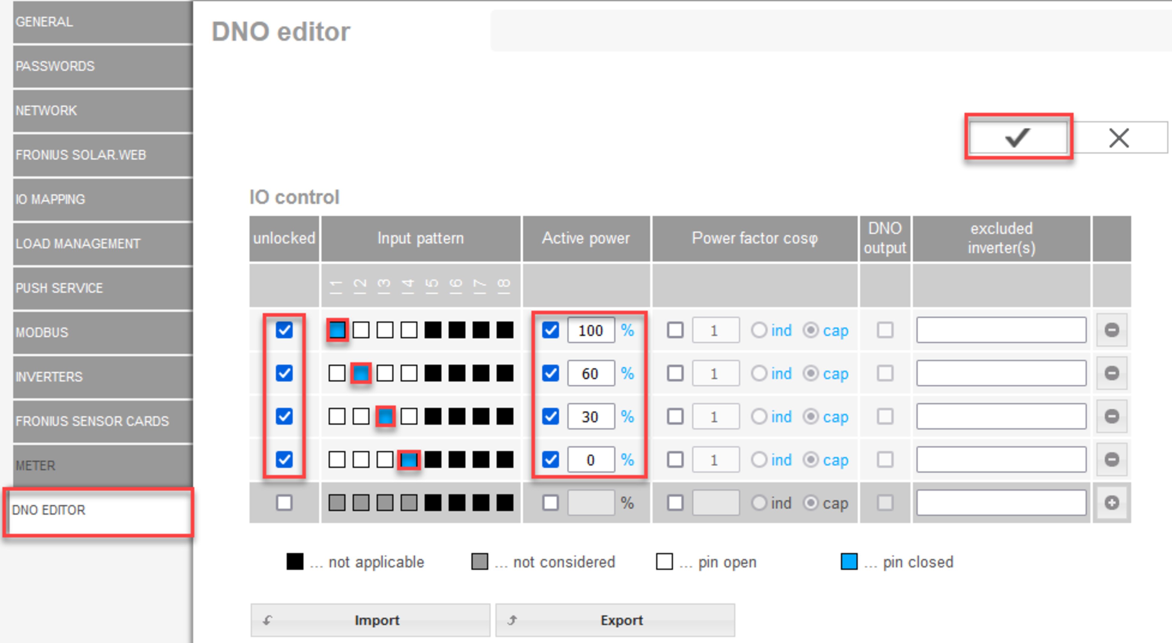
Overview of IO control user interface
- Select rows 1-4 in the "Unlocked" column
- Configure Input pattern
- Set the Effective power as follows:
- Rule 1: 100%, relay contact 1 closed
- Rule 2: 60%, relay contact 2 closed
- Rule 3: 30%, relay contact 3 closed
- Rule 4: 0%, relay contact 4 closed
- Tick the box to save the settings.
IMPORTANT!
Input patterns that are not taken into account must be avoided, because the activated rules are otherwise mutually exclusive. In this case, the dialog "Saving failed" appears when saving. Lines with failures are marked in red.
Connection diagram - 3 relays
The ripple control signal receivers and the I/Os terminals of the inverter are connected to one another using a 4-pole cable, in accordance with the connection diagram.
For cable lengths greater than 10 m between the inverter and the ripple control signal receiver, a shielded cable (CAT 5) is recommended.

| (1) | Ripple control signal receiver with three relays for effective power limitation |
| (2) | I/Os of the data communication area |
IO Control
Relay | Connection of Fronius Datamanager 2.0 | PIN |
|---|---|---|
1 | IO1 | 2 |
2 | IO2 | 3 |
3 | IO3 | 4 |
Settings on the UC Editor:
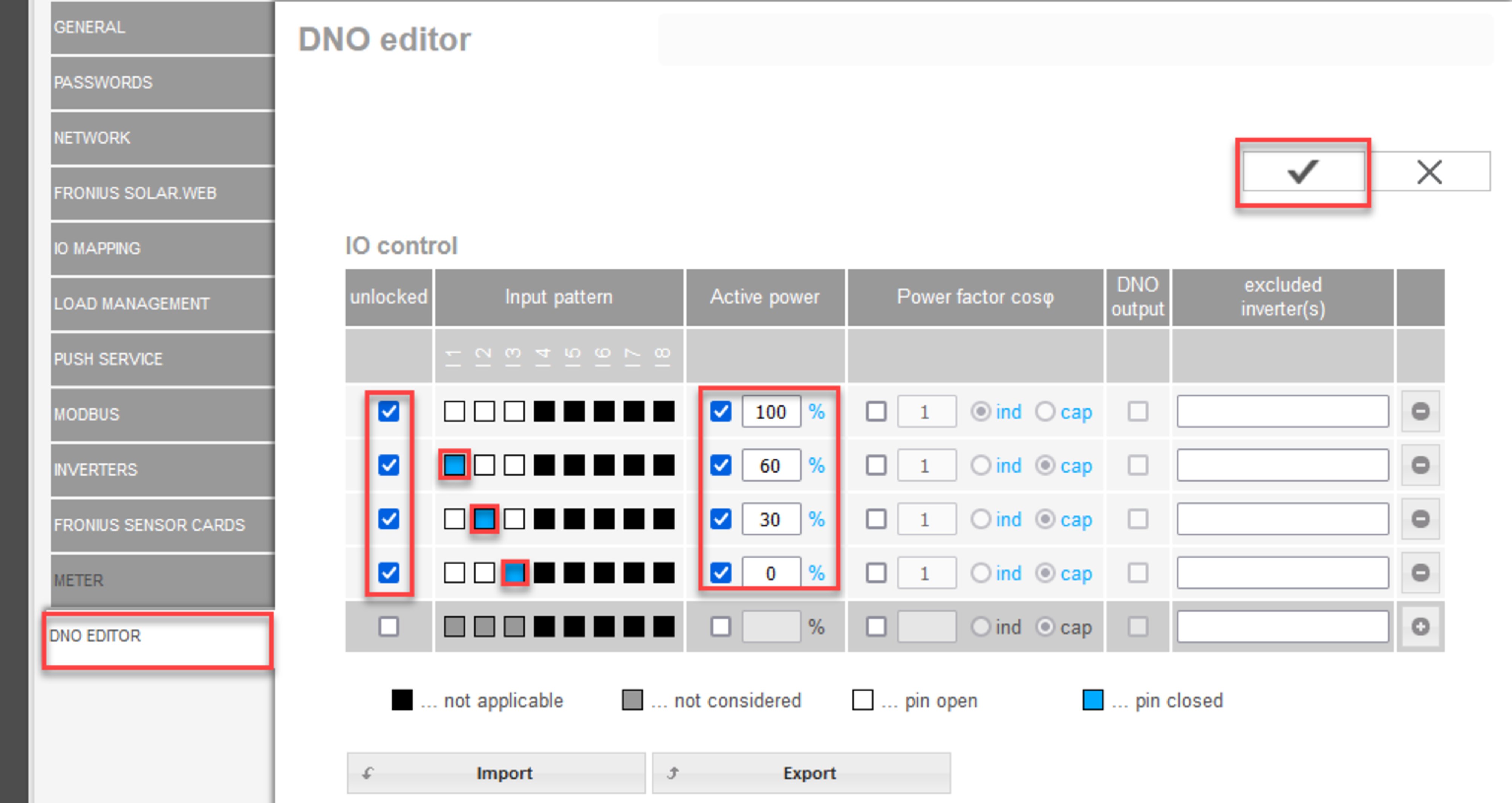
Overview of IO control user interface
- Select rows 1-4 in the "Unlocked" column
- Configure Input pattern for line 1-3
- Set the Effective power as follows:
- Line 1: 100%, all contacts open, no further rules defined
- Line 2 / rule 1 60%, relay contact 1 closed
- Line 3 / rule 2: 30%, relay contact 2 closed
- Line 4 / rule 3: 0%, relay contact 3 closed
- Tick the box to save the settings.
IMPORTANT!
Input patterns that are not taken into account must be avoided, because the activated rules are otherwise mutually exclusive. In this case, the dialog "Saving failed" appears when saving. Lines with failures are marked in red.
Connection diagram - 1 relay
The ripple control signal receivers and the I/Os terminals of the inverter are connected to one another using a 4-pole cable, in accordance with the connection diagram.
For cable lengths greater than 10 m between the inverter and the ripple control signal receiver, a shielded cable (CAT 5) is recommended.

| (1) | Ripple control signal receiver with one relay for effective power limitation. |
| (2) | I/Os of the data communication area |
IO Control
Relay | Connection of Fronius Datamanager 2.0 | PIN |
|---|---|---|
1 | IO1 | 2 |
Settings on the UC Editor:
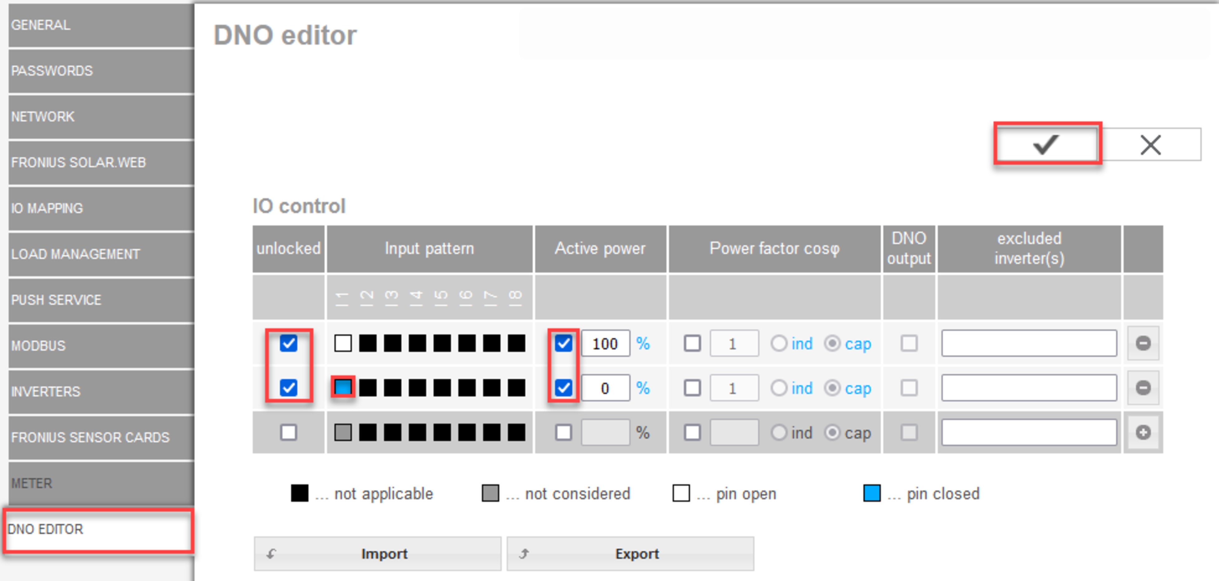
Overview of IO control user interface
- Select rows 1-2 in the "Unlocked" column
- Configure Input pattern
- Set the Effective power as follows:
- Rule 1: 100%, relay contact 1 open
- Rule 2: 0%, relay contact 1 closed
- Tick the box to save the settings.
IMPORTANT!
Input patterns that are not taken into account must be avoided, because the activated rules are otherwise mutually exclusive. In this case, the dialog "Saving failed" appears when saving. Lines with failures are marked in red.
Connection diagram - alternative with 2 relays
The ripple control signal receivers and the I/Os terminals of the inverter are connected to one another using a 4-pole cable, in accordance with the connection diagram.
For cable lengths greater than 10 m between the inverter and the ripple control signal receiver, a shielded cable (CAT 5) is recommended.
In this example, four power levels can be configured with two relays.

| (1) | Ripple control signal receiver with two relays for effective power limitation. |
| (2) | I/Os of the data communication area |
IO Control
Relay | Connection of Fronius Datamanager 2.0 | PIN |
|---|---|---|
1 | IO1 | 2 |
2 | IO2 | 3 |
Settings on the UC Editor:
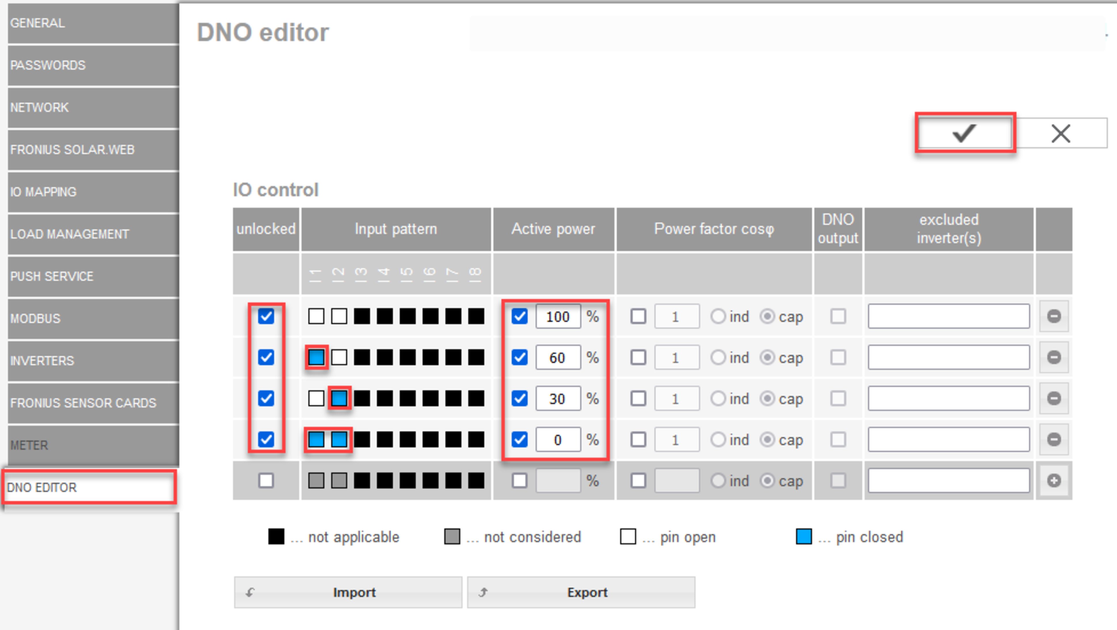
Overview of IO control user interface
- Select rows 1-4 in the "Unlocked" column
- Configure Input pattern for line 1-4
- Set the Effective power as follows:
- Rule 1: 100%, both relay contacts open
- Rule 2: 60%, relay contact 1 active, pin 2 closed / relay contact 2 not active, pin 3 open
- Rule 3: 30%, relay contact 1 not active, pin 2 open / relay contact 2 active, pin 3 closed
- Rule 4: 0%, both relay contacts closed
- Tick the box to save the settings.
IMPORTANT!
Input patterns that are not taken into account must be avoided, because the activated rules are otherwise mutually exclusive. In this case, the dialog "Saving failed" appears when saving. Lines with failures are marked in red.
Example of application with two ripple control receivers
The ripple control signal receivers and the I/O terminals of the inverter can be connected to one another as shown in the connection diagram.
For distances of over 10 m between the inverter and the ripple control signal receiver, a CAT 5 cable is recommended as a minimum and the shielding must be connected on one side at the push-in terminal of the data communication area (SHIELD).
In this example, the connection to two ripple control receivers is described. In this way, the effective power and power factor can be controlled at the same time.

Two ripple control receivers, connected to the Fronius Datamanager 2.0 IOs
| (1) | Ripple control receiver with three relays for effective power limitation |
| (2) | Ripple control receiver with three relays for power factor limitation |
| (3) | I/Os of the data communication area |
| (4) | Loads (e.g., signal light, signal relay) |
IO Control ripple control receiver 1 (effective power)
Relay | Connection of Fronius Datamanager 2.0 | PIN |
|---|---|---|
1 | IO1 | 2 |
2 | IO2 | 3 |
3 | I 4 | 4 |
IO Control ripple control receiver 2 (power factor)
Relay | Connection of Fronius Datamanager 2.0 | PIN |
|---|---|---|
1 | I 7 | 5 |
2 | I 8 | 6 |
2 | I 9 | 7 |
Settings on the UC Editor:
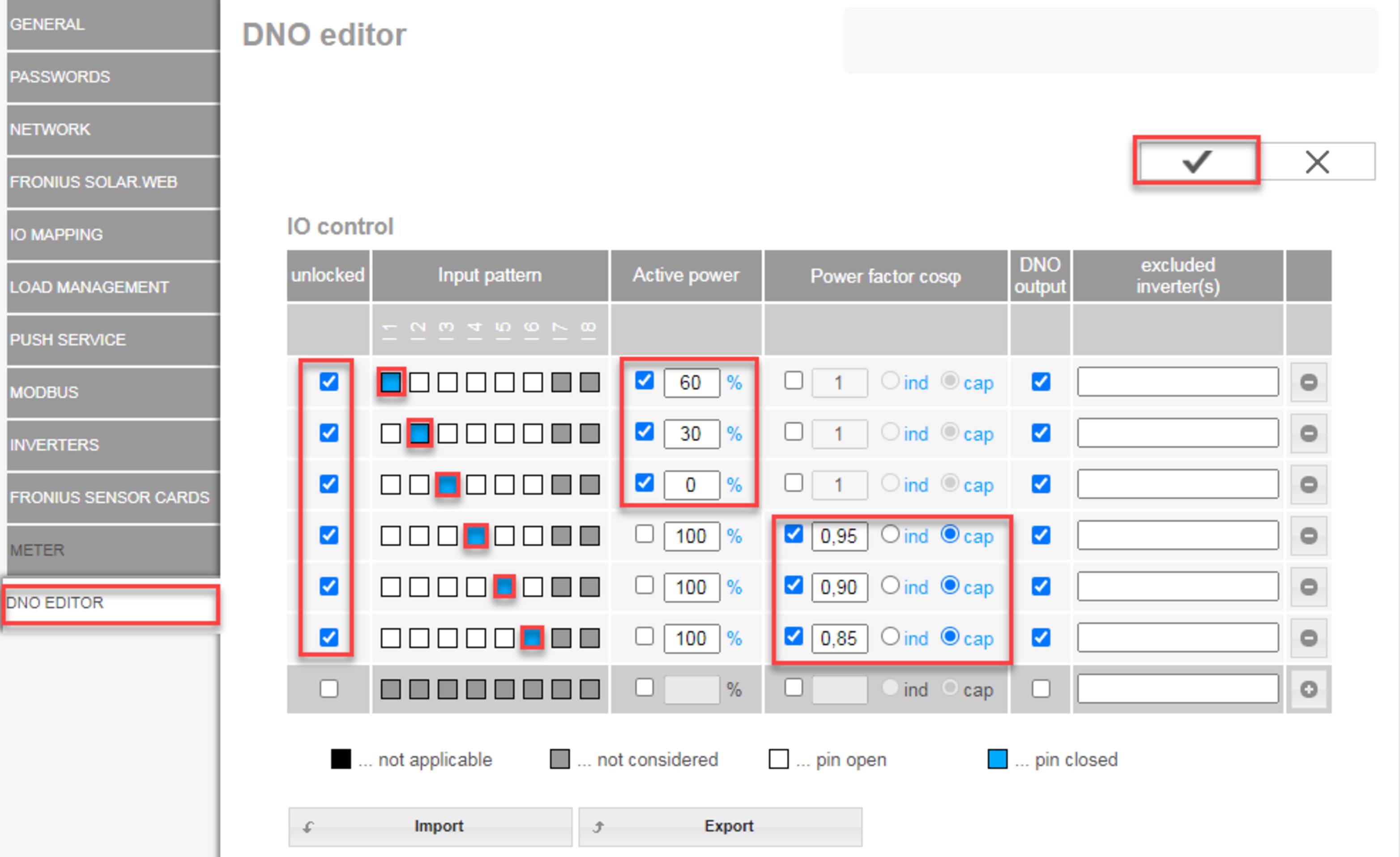
Overview of IO control user interface
- Select rows 1-6 in the "Unlocked" column
- Configure Input pattern for line 1-6
- Set the Effective power as follows:
- Rule 1: 100%, relay contact 1 closed
- Rule 2: 60%, relay contact 2 closed
- Rule 3: 30%, relay contact 3 closed
- Set the Power factor as follows:
- Rule 1: 0.95, relay contact 4 closed
- Rule 2: 0.90, relay contact 5 closed
- Rule 3: 0.85, relay contact 6 closed
- Tick the box to save the settings.
IMPORTANT!
Input patterns that are not taken into account must be avoided, because the activated rules are otherwise mutually exclusive. In this case, the dialog "Saving failed" appears when saving. Lines with failures are marked in red.
Connecting ripple control receiver to several inverters
The utility company may require that one or more inverters are connected to a ripple control receiver in order to limit the effective power and/or the power factor of the photovoltaic system.

Connection diagram for ripple control receiver with several inverters
The following Fronius inverters can be connected to a ripple control receiver via a distributor (coupling relay):
- Symo GEN24
- Primo GEN24
- Tauro
- Verto
- SnapINverter (only devices with Fronius Datamanager 2.0)
IMPORTANT!
The "4-relay operation" setting (see Connection diagram - 4 relays) must be activated on the user interface of each inverter connected to the ripple control receiver.
UC Editor—AUS—Demand Response Modes (DRM)
IMPORTANT! To control an inverter via DRM the inverter has to have a Fronius DRM Interface (item number 4,240,005). | |
| http://www.fronius.com/QR-link/4204102292 |
Reactive power output– to enter the reactive power output (= +Qrel) for DRM 3 in %
Reactive power input– to enter the reactive power input (= -Qrel) for DRM 7 in %
UC Editor – dynamic power reduction
Energy companies or utility companies can prescribe feed-in limits for an inverter (e.g., max. 70% of the kWp or max. 5 kW).
Dynamic power reduction takes account of self-consumption in the household before the power of an inverter is reduced:
- An individual limit can be set.
- A meter for determining self-consumption per S0 can be connected directly to the inverter.
- A Fronius Smart Meter can be connected to the Datamanager at the D-/D+ connections for Modbus data.
No limit – the inverter converts all available PV energy and feeds it into the public grid.
Limit for the entire system – The entire photovoltaic system is limited to a fixed power limit. A value must be set for the permissible total feed-in power.
Limit per phase (not for single-phase devices) - Each individual phase is measured. If the permissible feed-in limit is exceeded on one phase, the total power of the inverter is reduced until the value on the affected phase is permissible again (see example below). This setting is only necessary if required by national standards and regulations. The value of the permissible power of feeding in per phase must be set.
"Limit per phase" is limited to 20 inverters. When the limit is exceeded, the function of power limitation is no longer available.
Example: "Limit per phase" (set value 2000 W) | ||||
|---|---|---|---|---|
Max. possible production [kW] | 4 | 4 | 4 | 12 |
Set value | 2 | 6 | ||
Load requirement in the home network [kW] | 2 | 3 | 5 | 10 |
Load coverage in the domestic grid via PV system [kW] | 2 | 2 | 2 | 6 |
Drawn from the public grid [kW] | 0 | 1 | 3 | 4 |
Field for entering the total DC system power in Wp.
This value is used as a control reference and also in case of a fault (e.g., meter failure).
Field for entering the max. power in W or % (up to two figures after the decimal place, negative values are also possible)
If no meter has been selected under the "Meter" menu item:
max. power generated for the entire system
If Fronius Smart Meter or S0 inverter has been selected under the "Meter" menu item: max. energy fed into the grid
Hard Limit - If this value is exceeded, the inverter switches off within max. 5 seconds. This value must be higher than the value set for Soft Limit.
Soft Limit - If this value is exceeded, the inverter readjusts down to the set value within the time required by the national standards and regulations.
Dynamic feed-in limit with multiple inverters
To be able to manage the feed-in limits of energy companies or utilities centrally, a Fronius inverter (master) can control the dynamic feed-in limit for other Fronius inverters in the system (secondary devices). To do so, the following requirements must be met:
- Power limitation and the Limit multiple inverters (Soft Limit and I/O Power Management only) function are activated and configured on the user interface of the master (primary device).
- Master and secondary device(s) are physically connected to the same network router via LAN.
- Inverter control via Modbus TCP is activated and configured for all secondary devices.
- The Fronius Smart Meter is configured as a primary meter and connected to the master.
Dynamic feed-in limitation is available for the following device combinations:
Master | Secondary devices |
|---|---|
Fronius GEN24 | Fronius GEN24, Fronius Verto, Fronius Tauro, Fronius Argeno, Fronius SnapINverter with Fronius Datamanager 2.0* |
Fronius Verto | Fronius GEN24, Fronius Verto, Fronius Tauro, Fronius Argeno, Fronius SnapINverter with Fronius Datamanager 2.0* |
Fronius Tauro | Fronius GEN24, Fronius Verto, Fronius Tauro, Fronius Argeno, Fronius SnapINverter with Fronius Datamanager 2.0* |
System limits
- Systems with a maximum of 20 inverters (1 master + 19 secondary devices) are supported.
- The control system is designed for photovoltaic systems with a total output of up to 300 kW.
- The greater the system power, the greater the switching time between inverters.
- The use of a plant controller is recommended for systems >300 kW.
Secondary device
Secondary devices adopts the feed-in limit from the master. No data for the feed-in limit is sent to the master. The following configurations must be set for power limitation:
Secondary device user interface, Fronius Datamanager 2.0
1 Select the user Admin and enter the password for the Admin user.
2In the Modbus settings menu area, activate the Data output via Modbus and Inverter control via Modbus functions.
3In the UC Editor > Control priorities menu field, specify the control priorities for a Fail-Safe-scenario as follows:
- Modbus
- Dynamic power reduction
- I/O control
4Select the UC Editor > Dynamic power reduction menu field
5In the Feed-in limit menu item, activate the Limit for the entire system function and enter the following settings:
- Specify the total value for DC system power in W
- Activate the Dynamic feed-in limit (Soft Limit) and enter a value of 0 W for the Max. grid feed-in power.
- Activate the Reduce inverter power to 0 % if the connection to the Smart Meter is lost function
✓Dynamic feed-in limitation with several inverters is configured.
IMPORTANT!
The secondary device automatically stops feeding into the grid in the event of a communication failure, where the Modbus controller is not sending signals to the inverter.
UC Editor – Control priorities
Used to set control priorities for the ripple control signal receiver, the dynamic power reduction, and the control via Modbus
1 = highest priority, 3 = lowest priority