Installation location and position
Explanation of safety notices
DANGER!
Indicates immediate danger.
If not avoided, death or serious injury will result.
WARNING!
Indicates a potentially hazardous situation.
If not avoided, death or serious injury may result.
CAUTION!
Indicates a situation where damage or injury could occur.
If not avoided, minor injury and/or damage to property may result.
NOTE!
Indicates a risk of flawed results and possible damage to the equipment.
Safety
WARNING!
Danger due to incorrect operation and incorrectly performed work.
This may result in serious injury and damage to property.
Commissioning of the hybrid system may only be carried out by trained personnel in accordance with the technical regulations.
Read the Installation and Operating Instructions before installing and commissioning the equipment.
WARNING!
Danger due to work that has been carried out incorrectly.
This may result in serious injury and damage to property.
A surge protection device must only ever be installed and connected by a qualified electrical engineer.
Follow the safety rules.
Ensure that both the AC side and the DC side of the inverter are de-energised before carrying out any installation and connection work.
Fire prevention
CAUTION!
Danger due to poor or unprofessional installation.
This may result in damage to inverters and other live photovoltaic system components.
Poor or unprofessional installation can cause overheating of cables and terminal connections and result in arcs. These can cause heat damage, which in turn may lead to fires.
Observe the following when connecting AC and DC cables:
Tighten all terminals to the torque specified in the Operating Instructions
Tighten all grounding terminals (PE / GND), including free ones, to the torque specified in the Operating Instructions
Do not overload cables
Check cables for damage and verify that they are laid correctly
Take note of the safety instructions, Operating Instructions and any local connection regulations
Using fastening screws, always screw the inverter firmly to the mounting bracket to the torque specified in the Operating Instructions.
Ensure that the fastening screws are tight before starting the inverter!
Note! Fronius will not accept any costs associated with production downtimes, installer costs, etc., that may arise as the result of a detected arc and its consequences. Fronius accepts no liability for fires that can occur despite the presence of the integrated arc detection/extinguishing system (e.g. fires caused by a parallel arc).
Note! After an arc has been detected, the entire photovoltaic system must be checked for possible damage before resetting the inverter.
Observe the manufacturer's connection, installation and operating instructions at all times. To reduce the hazard potential to a minimum, perform all installation and connection work carefully according to the instructions and regulations.
Refer to the device Operating Instructions / Installation Instructions for the tightening torques to be used at the relevant terminal connections.
Proper use
The following actions constitute improper use:
- Any use above and beyond this purpose
- Making any modifications to the inverter that have not been expressly approved by Fronius
- Installing components that are not distributed or expressly approved by Fronius
- Operating the device with a battery that has not been approved by Fronius
- Operating the equipment with an energy meter that has not been approved by Fronius
Fronius shall not be liable for any damage resulting from such action.
No warranty claims will be entertained.
- Carefully studying and obeying the Installation and Operating Instructions
- Performing all stipulated inspection and maintenance work
When designing the photovoltaic system, ensure that all of its components are operated within their permitted operating ranges at all times.
Observe all the measures recommended by the solar module manufacturer to ensure that the solar module retains its properties in the long term.
Observe the stipulations of the power supply company concerning energy fed into the grid, emergency power mode and the operation of storage systems.
The Fronius Symo Hybrid is a grid-connected inverter with an emergency power function – it is not a stand-alone inverter. The following restrictions must therefore be observed in emergency power mode:- Emergency power mode may be in operation for at least 1500 hours
- Emergency power mode may be in operation for more than 1500 operating hours if 15% of the duration of the inverter's grid power feed operation is not exceeded at the relevant time
Choosing the location of the inverter
 |
| The inverter is suitable for indoor installation. |
 |
| The inverter is suitable for outdoor installation. Because of its IP 65 protection class, the inverter is resistant to water jets from any direction and can also be used in damp environments. |
 |
| In order to minimise the heating up of the inverter, do not expose it to direct insolation. Install the inverter in a protected location, e.g. in the vicinity of the solar modules or beneath the eaves. |
 |
| |
 |
| UDCmax at an altitude of: IMPORTANT! The inverter must not be installed or used at altitudes above 3400 m. |
 |
| |
 |
| Do not install the inverter in:
|
 |
| During certain operating phases the inverter may produce a slight noise. For this reason it should not be installed in an occupied living area. |
 |
| Do not install the inverter in:
|
 |
| Do not install the inverter in:
|
 |
| Do not install the inverter in:
|

Install only on a solid surface | ||
Max. ambient temperatures: -13 °F / +140 °F (-25 °C / +60 °C) | ||
Relative humidity: 0-100% | ||
The airflow within the inverter is from the right to the top (cold air taken in from the right, hot air dissipated out of the top). | ||
If the inverter is installed in a switch cabinet or a similar sealed area, then forced-air ventilation must be provided to ensure adequate heat dissipation. | ||
If the inverter is to be installed on the outer wall of a cattle shed, maintain a minimum all-round clearance of 2 m between the inverter and all ventilation and other openings in the building. |
Installation position of inverter
  |
| The inverter is suitable for vertical installation on a vertical wall or column. |
 |
| The inverter is suitable for a horizontal installation position. |
 |
| The inverter is suitable for installation on a sloping surface. |
 |
| Do not install the inverter on a sloping surface with its connection sockets at the top. |
 |
| Do not install the inverter at an angle on a vertical wall or column. |
 |
| Do not install the inverter horizontally on a vertical wall or pillar. |
  |
| Do not install the inverter on a vertical wall or pillar with its connection sockets facing upwards. |
 |
| Do not install the inverter overhanging with the connection sockets at the top. |
 |
| Do not install the inverter overhanging with the connection sockets at the bottom. |
 |
| Do not install the inverter on the ceiling. |
Fitting the inverter mounting bracket
Safety
WARNING!
Danger due to residual voltage in capacitors.
This may result in an electric shock.
Wait for the capacitors to discharge. The discharge time is five minutes.
CAUTION!
Danger due to dirt or water on the terminals and contacts of the inverter's connection area.
This may result in damage to the inverter.
When drilling, ensure that terminals and contacts in the connection area do not become dirty or wet.
The mounting bracket without a power stage set does not conform to the protection class of the inverter as a whole, and therefore must not be installed without a power stage set.
The mounting bracket should be protected from dirt and moisture during installation.
- the inverter is placed in the mounting bracket and permanently attached using screws,
- the cover for the data communication area is permanently attached to the inverter with screws.
Degree of protection IP 20 applies to the mounting bracket with no inverter and the venting duct.
Selecting wall plugs and screws
Important! Different fixings may be required to fit the mounting bracket depending on the type of underlying surface. Fixings are therefore not included in the scope of supply of the inverter. The installer is responsible for selecting the right type of fixing.
Recommended screws
To install the inverter, the manufacturer recommends the use of steel or aluminium screws with a diameter of 6 - 8 mm.
Opening the inverter
WARNING!
Danger from inadequate ground conductor connection.
This can result in serious injury and damage to property.
The housing screws provide a suitable ground conductor connection for grounding the housing and must NOT be replaced by any other screws that do not provide a reliable ground conductor connection.
1
2
3
4
Do not warp or deform the mounting bracket
Note! When fitting the mounting bracket to the wall, ensure that the mounting bracket does not become warped or deformed.


Fitting the mounting bracket to a wall
1
Tip: Install the inverter so that its display is at eye level
2
3
Note! When mounting the mounting bracket on the wall, ensure that the mounting bracket does not become warped or deformed.
Installing the mounting bracket on a mast or beam

When installing the inverter on a mast or support, Fronius recommends the "Pole Clamp" kit from Rittal GmbH (order no. SZ 2584.000).
This kit enables the inverter to be installed on round or rectangular masts with the following diameters: Æ from 40 to 190 mm (round mast), ÿ from 50 to 150 mm (rectangular mast)
Fitting the mounting bracket to metal supports
The mounting bracket must be affixed at a minimum of four points.
1
Connecting the inverter to the public grid (AC side)
Safety
WARNING!
Incorrect operation or poorly executed work can cause serious injury or damage.
Commissioning of the hybrid system may only be carried out by trained personnel in accordance with the technical regulations. Read the Installation and Operating Instructions before installing and commissioning the equipment.
WARNING!
An electric shock can be fatal.
Danger due to grid voltage and DC voltage from solar modules that are exposed to light.
Ensure that both the AC side and the DC side of the inverter are de-energised before carrying out any connection work.
Only an authorised electrical engineer is permitted to connect this equipment to the public grid.
WARNING!
An electric shock can be fatal.
Danger due to grid voltage and DC voltage from solar modules or battery.
The DC main switch is only to be used to de-energise the power stage set. The connection area is still live when the DC main switch is switched off.
Ensure that the power stage set and connection area are disconnected from one another before carrying out any maintenance or service tasks.
The power stage set is only to be disconnected from the mounting bracket once it is de-energised.
Maintenance and servicing in the power stage set of the inverter must only be carried out by Fronius-trained service technicians.
CAUTION!
Risk of damage to the inverter as the result of incorrectly tightened terminals.
Incorrectly tightened terminals can cause heat damage to the inverter that may result in a fire. When connecting AC and DC cables, ensure that all the terminals are tightened to the specified torque.
Monitoring the grid
To provide the best possible grid monitoring, the resistance in the leads to the AC-side terminals should be as low as possible.
AC terminal
1.
Ground conductor / grounding
2.
L1 - L3 phase conductor
3.
Neutral conductor
4.
M32 screw connection
Ø 11 - 21 mm
Ø 11 - 21 mm
5.
Copper or aluminium: solid round conductor
Copper: fine-stranded round conductor up to conductor class
min. 2.5 mm² - max. 16 mm²
Copper: fine-stranded round conductor up to conductor class
min. 2.5 mm² - max. 16 mm²
6.
PE: > 250 mm + 15 mm (stripped)
L1, L2, L3 and N: > 200 mm + 15 mm (stripped)
L1, L2, L3 and N: > 200 mm + 15 mm (stripped)
- Max. cross-section of each conductor cable: 16 mm²
- Min. cross-section of each conductor cable: in accordance with the fuse rating on the AC side, but at least 2.5 mm²
- The AC cables can be connected to the AC terminals without ferrules.
- In the case of an AC cable with a cross-section of 16 mm², ferrules can be either not used or only used to a limited extent depending on the type of ferrule and crimping.
Type of AC cable
The following types of AC cable can be connected to the AC terminals of the inverter:
 |
|
Preparing the aluminium cables for connection
The AC-side terminals are suitable for connecting single-wire, round aluminium cables. Because of the formation of a non-conductive oxide layer due to the reaction of aluminium with air, the following points must be considered when connecting aluminium cables:
- the reduced rated currents for aluminium cables
- the connection conditions listed below
Always follow the cable manufacturer instructions when using aluminium cables.
When designing cable cross-sections, take local regulations into account.
Connection conditions:
1Carefully clean the oxide layer from the bare end of the cable by scraping it, e.g. with a knife
IMPORTANT! Do not use brushes, files or emery paper, as the aluminium particles get trapped and can be transferred to other conductors.
2Once the oxide layer is removed, rub the end of the cable with a neutral grease, such as non-acidic and non-alkaline Vaseline
3Immediately connect the cable end to the terminal
IMPORTANT!Repeat the procedure if the cable has been disconnected and is to be re-connected.
Cross section of the AC cable
For a standard M32 metric screw joint with a reducer:
Cable diameter from 7-15 mm
When using an M32 metric screw joint (reducer removed):
cable diameter from 11-21 mm(with a cable diameter of less than 11 mm, the strain-relief force is reduced from 100 N to a maximum of 80 N)
With cable diameters greater than 21 mm, the M32 screw joint must be replaced by an M32 screw joint with a larger clamping area – item number: 42,0407,0780 – strain-relief device M32 x 1.5 KB 18–25.
Requirements for the neutral conductor
- Ensure that the grid neutral conductor is grounded. This may not be the case for IT grids (insulated grids with no grounding); it will then not be possible to use the inverter.
- In order to use the inverter, the neutral conductor must be connected. A neutral conductor that is too small may adversely affect the inverter feeding energy into the grid. The neutral conductor must therefore be the same size as the other live conductors.
Connecting the inverter to the public grid (AC)
1.
Switch off the residual current circuit breaker.
2.
Thread the cable from below through the strain-relief device.
3.
Fasten the cap nut M32 of the strain-relief device.
4.
Connect PE ground conductor.
5.
Connect phase conductors L1, L2, L3 and neutral conductor N.
6.
Secure the connected cables with a screwdriver. Observe the torque values marked on the side underneath the terminals.
Routing the AC cables
- Form loops with the AC cables when connecting them to the AC terminals.
- When securing the AC cables using a metric screw joint, ensure that the loops do not protrude beyond the connection area.
Otherwise, under certain circumstances it may no longer be possible to close the inverter.
IMPORTANT! The PE ground conductor of the AC cable must be laid in such a way that it is the last to be disconnected in the event that the strain-relief device should fail.
This can be ensured, for example, by making it somewhat longer and by laying it in a loop.
If AC cables are laid over the shaft of the DC main switch or across the connection block of the DC main switch, they may be damaged when the inverter is swung in, or they may even prevent the inverter from being swung in.
IMPORTANT! Do not lay AC cables over the shaft of the DC main switch or across the connection block of the DC main switch.
1.
Do not lay AC cables over the shaft of the DC main switch or across the connection block of the DC main switch.
2.
Correct installation of the cables.

If overlength AC or DC cables are to be laid in loops in the connection area, attach the cables with cable ties to the eyelets provided on the top and bottom of the connection block.
Maximum fuse rating on alternating current side

Inverter | Phases | AC output | Maximum output overcurrent protection | Recommended fuse rating |
|---|---|---|---|---|
Symo Hybrid 3.0 | 3 + N | 3000 W | 4 x C 25 A | 4 x C 16 A |
Symo Hybrid 4.0 | 3 + N | 4000 W | 4 x C 25 A | 4 x C 16 A |
Symo Hybrid 5.0 | 3 + N | 5000 W | 4 x C 25 A | 4 x C 16 A |

NOTE!
Local regulations, the electricity retailer or other factors may require an earth-leakage circuit breaker in the AC connection lead.
For this situation, a type A earth-leakage circuit breaker with a tripping current of at least 100 mA is generally adequate. In particular cases, and depending on local factors, however, the type A earth-leakage circuit breaker may trip at the wrong time. For this reason, Fronius recommends that an earth-leakage circuit breaker that is suitable for frequency converters should be used.
Connecting solar module strings to the inverter
Safety
WARNING!
Incorrect operation or poorly executed work can cause serious injury or damage.
Commissioning of the hybrid system may only be carried out by trained personnel in accordance with the technical regulations. Read the Installation and Operating Instructions before installing and commissioning the equipment.
WARNING!
An electric shock can be fatal.
Danger due to grid voltage and DC voltage from solar modules that are exposed to light.
Ensure that both the AC side and the DC side of the inverter are de-energised before carrying out any connection work.
Only an authorised electrical engineer is permitted to connect this equipment to the public grid.
WARNING!
An electric shock can be fatal.
Danger due to grid voltage and DC voltage from solar modules or battery.
The DC main switch is only to be used to de-energise the power stage set. The connection area is still live when the DC main switch is switched off.
Ensure that the power stage set and connection area are disconnected from one another before carrying out any maintenance or service tasks.
The power stage set is only to be disconnected from the mounting bracket once it is de-energised.
Maintenance and servicing in the power stage set of the inverter must only be carried out by Fronius-trained service technicians.
CAUTION!
Risk of damage to the inverter as the result of incorrectly tightened terminals.
Incorrectly tightened terminals can cause heat damage to the inverter that may result in a fire. When connecting AC and DC cables, ensure that all the terminals are tightened to the specified torque.
CAUTION!
Risk of damage to inverter from overload.
The maximum amperage when connecting to a single DC terminal is 32 A.
Connect the DC+ and DC- cables to the DC+ and DC- terminals on the inverter, taking care to ensure that the polarity is correct.
The maximum DC input voltage must not exceed 1000 V DC.
NOTE!
The solar modules connected to the inverter must comply with the IEC 61730 Class A standard.
NOTE!
When photovoltaic modules are exposed to light they supply current to the inverter.
General comments regarding solar modules
To enable suitable solar modules to be chosen and to use the inverter as efficiently as possible, it is important to bear the following points in mind:
- If insolation is constant and the temperature is falling, the open circuit voltage of the solar modules will increase. The open circuit voltage must not exceed the maximum permissible system voltage. If the open circuit voltage exceeds the specified values, the inverter will be destroyed and no warranty claims will be entertained.
- The temperature coefficients on the solar modules data sheet must be observed.
- More exact values for dimensioning the solar modules can be provided by suitable calculation programs, like the Fronius Solar.creator (creator.fronius.com).
Note! Before connecting up the solar modules, check that the voltage for the solar modules specified by the manufacturer corresponds to the actual measured voltage.
DC terminals

Max. cross-section of each DC cable:
10 mm²
Min. cross-section of each DC cable:
2.5 mm²
The DC cables can be connected to the DC terminals without ferrules.

To ensure effective strain relief of the solar module strings, only use cables with identical cross-sections.
In the case of a DC cable with a cross-section of 16 mm², ferrules can be either not used or only used to a limited extent depending on the type of ferrule and crimping.
Connecting aluminium cables
The DC-side terminals are suitable for connecting single-wire, round aluminium cables. Because of the formation of a non-conductive oxide layer due to the reaction of aluminium with air, the following points must be considered when connecting aluminium cables:
- the reduced rated currents for aluminium cables
- the connection conditions listed below
Note! Always follow the cable manufacturer instructions when using aluminium cables.
Note! When designing cable cross-sections, take local regulations into account.
Connection conditions:
1Carefully clean the oxide layer from the bare end of the cable by scraping it, e.g. with a knife
IMPORTANT! Do not use brushes, files or emery paper, as the aluminium particles get trapped and can be transferred to other conductors.
2Once the oxide layer is removed, rub the end of the cable with a neutral grease, such as non-acidic and non-alkaline Vaseline
3Immediately connect the cable end to the terminal
IMPORTANT! Repeat the procedure if the cable has been disconnected and is to be re-connected.
Do not ground the poles of the solar modules

The hybrid inverter is a transformerless device. The individual poles of the solar modules must not be grounded.
Solar module strings - checking the polarity and voltage

CAUTION!
Risk of possible damage to the inverter!
Check the polarity and voltage of the solar module strings before making the connection. The voltage must not exceed the following values:
when installed between 0 and 2000 m above sea level: 1000 V
when installed between 2001 and 2500 m above sea level: 900 V
when installed between 2501 and 3000 m above sea level: 815 V
when installed between 3001 and 3400 m above sea level: 750 V
Connecting solar module strings to the inverter (DC)
Only break out as many target break points as there are cables.
1.
Loosen screws, 2 screws TX 20.
2.
Remove the cover.
3.
Only break out as many target break points as there are cables.
4.
Disconnect the connection to the PV modules.
5.
Observe the maximum length and diameter of the cables.
6.
Use cables with the same diameters.
7.
Thread in the PV+/PV- cables.
8.
Pull back the PV cables by 2 cm ...
9.
... so that the rubber seals are bulging out.
10.
Connect PV+/PV- cables to the appropriate terminal point.
11.
Secure the connected cables with a screwdriver. Observe the printed torque data!
12.
Secure the cover. 2 x TX 20 screws.
13.
Connect PV modules. Caution! DC voltage! Note +/-!
Routing the DC cables

If DC cables are laid over the shaft of the DC main switch or across the connection block of the DC main switch, they may be damaged when the inverter is swung in or they may even prevent the inverter from being swung in.
IMPORTANT! Do not lay DC cables over the shaft of the DC main switch or across the connection block of the DC main switch.
If overlength AC or DC cables are to be laid in loops in the connection area, attach the cables with cable ties to the eyelets provided on the top and bottom of the connection block.
Connecting the battery to the inverter
Connecting the battery DC cables to the inverter
Only break out as many target break points as there are cables.
1.
Loosen screws, 2 screws TX 20.
2.
Remove the cover.
3.
Only break out as many target break points as there are cables.
4.
Disconnect the connection to the PV modules.
5.
Observe the maximum length and diameter of the cables.
6.
Use cables with the same diameters.
7.
Switch off the Fronius Solar Battery (OFF).
8.
Remove 2 fuses of the Fronius Solar Battery.
9.
Remove 3 - 8 fuses of the battery modules.
10.
Thread in the BAT+/BAT-/BAT PE cables from below.
11.
Pull back the BAT cable by 2 cm ...
12.
... so that the rubber seals are bulging out.
13.
Connect the BAT cable to the appropriate terminal point.
14.
Secure the connected cables with a screwdriver. Observe the printed torque data!
15.
Refit the 3 - 8 fuses of the battery modules.
16.
Refit the 2 fuses of the Fronius Solar Battery.
17.
Switch on the Fronius Solar Battery (ON).
18.
Secure the cover. 2 x TX 20 screws.
19.
Connect PV modules. Caution! DC voltage! Note +/-!
Overview of Fronius Energy Package DC cabling

Connecting the Modbus cables to the inverter
IMPORTANT! Operating the inverter with a free broken-out option card slot is not permitted.
An appropriate blanking cover (42,0405,2020) to cover the slot is available from Fronius as an option.
IMPORTANT! If data communication cables are wired into the inverter, observe the following points:
- Depending on the number and cross-section of the data communication cables that are being introduced, take the relevant blanking plugs out of the sealing insert and insert the data communication cables.
- The relevant blanking plugs must be inserted into the free openings on the sealing insert.
1
2
3
4
5
6
7
Terminating resistor for Modbus cable
The terminating resistor must be set according to how the individual devices are configured (see diagram below).
 | ||
*) The R 120 Ohm terminating resistor is supplied with the Fronius Smart Meter A DC connection and ground connection must also be established between the battery and the inverter. The connection of the individual lines was illustrated in the preceding chapters. The installer is responsible for choosing the cables. |
Example data cabling for BYD - Fronius Symo Hybrid - Fronius Smart Meter
Cabling variant 1:

Cabling variant 2:

Attaching the inverter to the mounting bracket
Attaching the inverter to the mounting bracket
WARNING!
Danger from inadequate ground conductor connection.
This can result in serious injury and damage to property.
The housing screws provide a suitable ground conductor connection for grounding the housing and must NOT be replaced by any other screws that do not provide a reliable ground conductor connection.
The side sections of the housing lid are designed to function as holding and carrying handles.
Note! For safety reasons, the inverter is fitted with a latch that prevents the inverter from being swung into the mounting bracket unless the DC main switch is switched off.- Never attach the inverter to the mounting bracket or swing it in unless the DC main switch is switched off.
- Never use force to attach the inverter or swing it in.
The fastening screws in the data communication area of the inverter are used for securing the inverter to the mounting bracket. Correctly tightened fastening screws are a prerequisite if proper contact is to be established between the inverter and mounting bracket.
CAUTION!
Danger due to incorrectly tightened fastening screws.
This may result in arcs occurring when the inverter is in operation, which may lead to fire.
Always use the specified torque when tightening the fastening screws.
1
2
3
4
Starting for the first time
Starting the inverter for the first time
WARNING!
Incorrect operation or poorly executed work can cause serious injury or damage.
Commissioning of the hybrid system may only be carried out by trained personnel in accordance with the technical regulations. Read the Installation and Operating Instructions before installing and commissioning the equipment.
When starting the inverter for the first time, it is necessary to select various setup settings.
If setup is interrupted before it is complete, it can be restarted by means of an AC reset. An AC reset can be carried out by switching the automatic circuit breaker off and on again.
The country setup can only be set when using the inverter for the first time. If the country setup needs to be changed at a later date, please contact your Technical Support team.
1
2
3
* Country setup examples | ||||||||||||||||||||||||||||||||||||||||||||||||||||||||||||||||||||||||||||||||||||||||||||||||||||||||
|---|---|---|---|---|---|---|---|---|---|---|---|---|---|---|---|---|---|---|---|---|---|---|---|---|---|---|---|---|---|---|---|---|---|---|---|---|---|---|---|---|---|---|---|---|---|---|---|---|---|---|---|---|---|---|---|---|---|---|---|---|---|---|---|---|---|---|---|---|---|---|---|---|---|---|---|---|---|---|---|---|---|---|---|---|---|---|---|---|---|---|---|---|---|---|---|---|---|---|---|---|---|---|---|---|
|
|
| ||||||||||||||||||||||||||||||||||||||||||||||||||||||||||||||||||||||||||||||||||||||||||||||||||||||
4
5
Activating the emergency power function
Prerequisites for emergency power mode
- Correct cabling of the emergency power system in the electrical installation (see document entitled "Fronius Energy Package - Examples of emergency power switchover")
- The meter (Fronius Smart Meter) must be installed at the feed-in point and configured
- Latest firmware on the inverter - if required, perform a firmware update
- Select Alternative (emergency power) setup in the CONFIG menu on the inverter (see Installation Instructions)
- Change the required settings in the emergency power area in the IO mapping menu (Fronius system monitoring web page → Settings → IO mapping → Emergency power)
- Set the system to "Auto" in the emergency power system overview (Fronius system monitoring web page → Settings → System overview → Emergency power operating mode)
If there are additional inverters in the system, these should be installed outside of the emergency power circuit, but within that for the Fronius Smart Meter.
Accessing the CONFIG menu
 | 1Press the "Menu" key | |
 |
| The menu level appears. 2Press the unassigned "Menu / Esc" key 5 times  |
 | 'Access Code' is displayed in the 'CODE' menu; the first digit starts flashing. | |
 | 3Enter the access code for the CONFIG menu: Use the 'Up' and 'Down' keys to select a value for the first digit of the code | |
 | 4Press the 'Enter' key |
 | The second digit flashes. | |
5Repeat steps 3 and 4 for the second, third, fourth and fifth digits of the access code until... | ||
 | the selected code starts flashing. | |
| 6Press the 'Enter' key | |
The first parameter of the CONFIG menu is displayed |
Selecting alternative (emergency power) setup
- EmergencyPower 50Hz: for all countries with a nominal frequency of 50 Hz
- EmergencyPower 60Hz: for all countries with a nominal frequency of 60 Hz
 | | 1Use the 'Up' and 'Down' keys to select the Alternative (emergency power) setup |
| 2Press the 'Enter' key |
Fronius Ohmpilot and emergency power mode
The Fronius Ohmpilot is not suitable for emergency power mode.
If a Fronius Ohmpilot is used, it should be installed outside of the emergency power circuit
- switch off the circuit breaker on the Fronius Ohmpilot (if fitted)
- or set heating element measurement on the Ohmpilot to manual (under 'General - General Settings - Heater 1 - Manual') and turn off the 'Legionella prevention (h)' and 'Adapt day curve' settings (under 'General - General Settings - Heater 1'). The power level required for these functions exceeds the power limits in emergency power mode. Since these functions are blocked when emergency power mode starts, these settings cannot be changed during a power failure and must be specified beforehand.
- do not turn on boost mode on the Ohmpilot
Installing Fronius system monitoring – Overview
Safety
WARNING!
Danger from incorrect operation
This can result in severe personal injury and damage to property.
Do not use the functions described here until you have fully read and understood the Operating Instructions of every system component:
Do not use the functions described here until you have read and understood all the safety rules.
IMPORTANT! Knowledge of networking systems is required in order to install Fronius system monitoring.
Starting for the first time
IMPORTANT! Starting up the Fronius system monitoring function for the first time is made considerably easier with the Fronius Solar.start app. The Fronius Solar.start app is available in the respective app stores.
 |  |
Or visit |
|
https://wizard.solarweb.com to select the desired menu item | |
IMPORTANT! In order to establish a connection to Fronius system monitoring, the end device in question (e.g. laptop, tablet, etc.) must be set up as follows:
- "Obtain IP address automatically (DHCP)" must be activated
1Switch the device to Service mode
- Activate the WLAN Access Point via the Setup menu on the inverter
The inverter establishes the WLAN access point. The WLAN access point remains open for 1 hour.
Installation using the Solar.start app 2Download the Fronius Solar.start App  3Run the Fronius Solar.start app |
| Installation using a web browser 2Connect the end device to the WLAN access point SSID = FRONIUS_239.xxxxx (4-8 digits)
3Enter the following in the browser: http://datamanager or 192.168.250.181 (IP address for WLAN connection) or 169.254.0.180 (IP address for LAN connection) |
The Setup wizard start page is displayed.
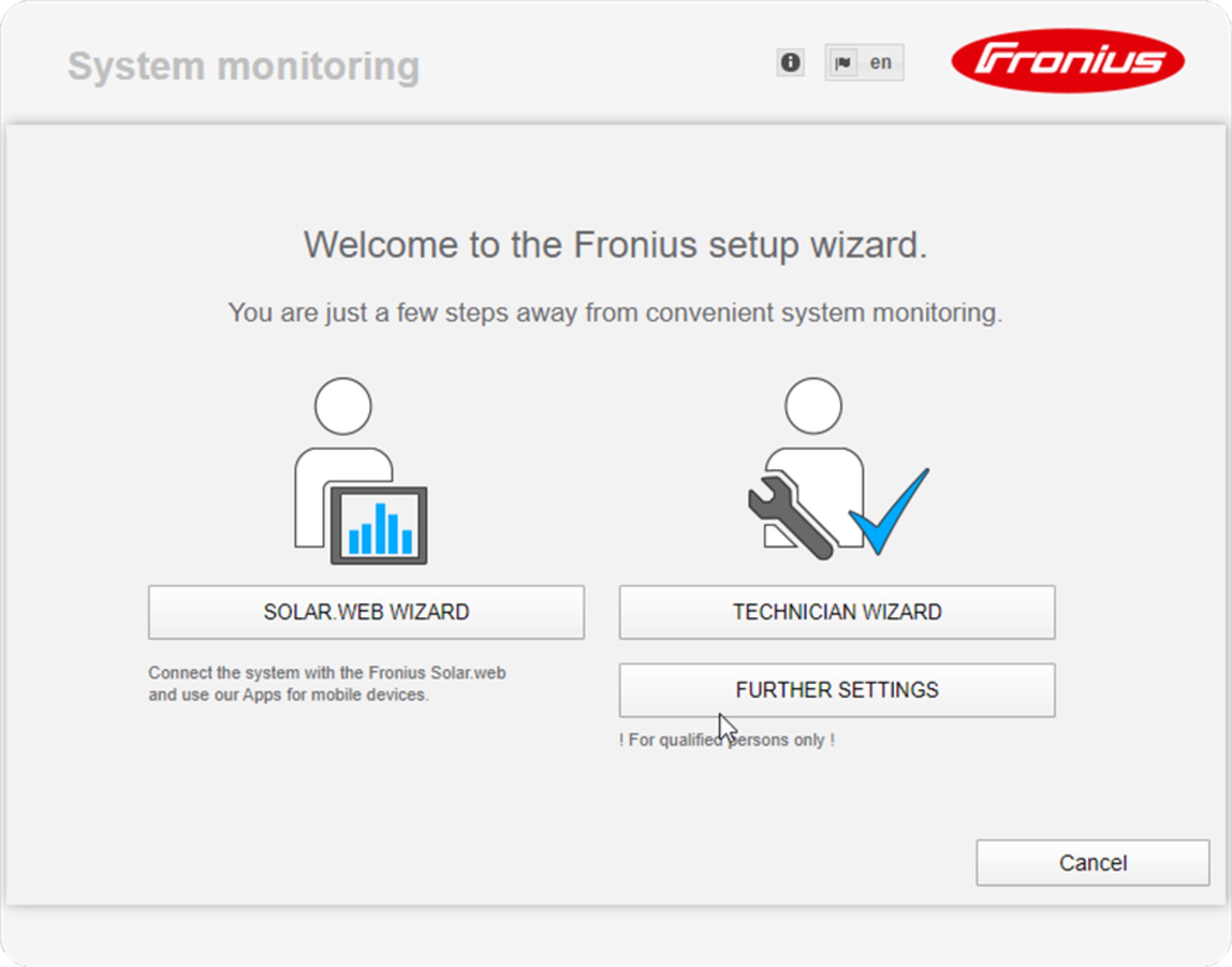
If you run the technician wizard, always remember to make a note of the assigned service password. This service password is required to enter settings in the "System overview" and "DNO Editor" menus as well as for advanced battery settings.
If the technician wizard is not run, no specifications regarding power reduction are set and hybrid mode is not possible (charging and discharging of the battery)
4Run the technician wizard and follow the instructions
NOTE!
Danger of deep discharge of an unactivated battery
This may result in permanent damage to the battery.
The Solar Web wizard needs to be run in order to activate the battery and, if necessary, the Smart Meter.
5Run the Solar Web wizard and follow the instructions
The Fronius Solar.start homepage
or
the Fronius system monitoring web page is displayed.
Information to help you work through the Solar Web wizard
The solar web wizard consists of 5 steps:
1. General
General system data (e.g. system name) is entered here
2. Service password
Enter (and make a note of) the service password
3. IO assignment
Settings for the IO interface are entered (see also "Fronius Energy Package - IO assignment" Operating Instructions)
4. System overview
Settings for the entire PV system are entered (see also "Fronius Energy Package - System overview" Operating Instructions)
5. Dynamic power
Settings for dynamic power reduction are entered (see also "Fronius Energy Package - Dynamic power reduction" Operating Instructions)
Once you have worked your way through the Solar Web wizard, an automatic process is triggered to calibrate all the components. This involves charging the Fronius Solar Battery fully. After that, the system automatically starts in the set operating mode.
This calibration charging process is also performed automatically during actual operation after a number of charging and discharging cycles. When this calibration charge is performed depends on a number of different factors, such as the average state of charge or the energy throughput through the battery. The time can therefore vary depending on the time of year as well.
If the "permit battery charging from PSC grid" setting is deactivated, this calibration charging process relies exclusively on energy from the photovoltaic system when operating under normal conditions. Depending on the insolation conditions and size of the systems concerned, the charging process can take a very long time.
If the "permit battery charging from PSC grid" setting is activated, the calibration charging process is performed by drawing a constant current from the photovoltaic system and DSO (distribution system operator) grid.
IMPORTANT! The automatic process for fully charging the battery may result in energy being drawn from the DSO grid. The process can take several hours and cannot be aborted.
Notes regarding maintenance
Maintenance
Note! When installed outdoors in a horizontal position: once a year, check that all screw joints are tight!
Maintenance and servicing may only be carried out by Fronius-trained service technicians.
Maintenance
Note! When installed outdoors in a horizontal position: once a year, check that all screw joints are tight!
Maintenance and servicing may only be carried out by Fronius-trained service technicians.
Cleaning
Clean the inverter as required with a damp cloth.
Do not use cleaning agents, abrasives solvents or similar to clean the inverter.