Operating Instructions Fronius Energy Package

The warnings and safety instructions in these instructions are intended to protect people from possible injury and the product from damage.
Indicates an immediately dangerous situation
Serious injury or death will result if appropriate precautions are not taken.
Action step to escape the situation
Indicates a potentially dangerous situation
Death or serious injury may result if appropriate precautions are not taken.
Action step to escape the situation
Indicates a potentially dangerous situation
Minor or moderate injury may result if appropriate precautions are not taken.
Action step to escape the situation
Indicates impaired work results and/or damage to the device and components
The warnings and safety instructions are an integral part of these instructions and must always be observed to ensure the safe and proper use of the product.
The Operating Instructions must always be at hand wherever the device is being used. In addition to the Operating Instructions, attention must also be paid to any generally applicable and local regulations regarding accident prevention and environmental protection.
All safety and danger notices on the device:The terminals can reach high temperatures.
Only operate the device when all protection devices are fully functional. If the protection devices are not fully functional, there is a danger of:Any safety devices that are not fully functional must be repaired by an authorised specialist before the device is switched on.
Never bypass or disable protection devices.
For the location of the safety and danger notices on the device, refer to the section headed "General remarks" in the Operating Instructions for the device.
Any equipment malfunctions which might impair safety must be remedied before the device is turned on.
This is for your personal safety!
Betrieb oder Lagerung des Geräts außerhalb des angegebenen Bereichs gilt als nicht bestimmungsgemäß.
This document provides detailed information and instructions to ensure that all users can use the device safely and efficiently.
The maximum sound power level of the inverter is specified in the Technical Data.
The device is cooled as quietly as possible with the aid of an electronic temperature control system; this depends on the amount of converted power, the ambient temperature, the level of soiling of the device, etc.
It is not possible to provide a workplace-related emission value for this device because the actual sound pressure level is heavily influenced by the installation situation, the power quality, the surrounding walls and the properties of the room in general.
In certain cases, even though a device complies with the standard limit values for emissions, it may affect the application area for which it was designed (e.g., when there is equipment that is susceptible to interference at the same location, or if the site where the device is installed is close to either radio or television receivers). If this is the case, then the operator is obliged to take action to rectify the situation.
This system is equipped with an emergency power function. This means a backup power supply is automatically established in the event of a power outage.
The emergency power sticker provided with the inverter must be attached to the electrical distributor.
For maintenance and installation work, the system must both be isolated from the grid, and backup power mode must be disabled by opening the integrated DC disconnector on the inverter.
The emergency power supply is automatically activated and deactivated depending on the insolation conditions and the state of charge of the battery. This means that emergency power can be re-established unexpectedly when in standby mode. For this reason, when the emergency power supply is deactivated, switch off all connected devices and do not undertake any installation work on the household network.
Copyright of these operating instructions remains with the manufacturer.
Text and illustrations were accurate at the time of printing, subject to change.
We are grateful for suggestions for improvement and information regarding any discrepancies in the operating instructions.

Device design:
| (1) | Housing cover |
| (2) | Inverter |
| (3) | Mounting bracket |
| (4) | Connection area including DC main switch |
| (5) | Data communication area |
| (6) | Data communication cover |
The hybrid inverter converts the direct current generated by the PV modules into alternating current. This alternating current is synchronized with the grid voltage and fed into the public grid. Moreover, the solar energy can also be stored in a connected battery for later use.
The hybrid inverter has been developed specifically for use in grid-connected photovoltaic systems. A backup power mode is possible if the cabling is set up accordingly.
Thanks to its design and operating principle, the inverter is extremely safe both to install and to operate.
The inverter monitors the public grid automatically. In the event of abnormal grid conditions, the inverter ceases operating immediately and stops feeding power into the grid (e.g. if the grid is switched off, if there is an interruption, etc.).
The grid is monitored by monitoring the voltage, frequency and islanding conditions. The inverter switches to backup power mode if it has been cabled up accordingly.
Operation of the inverter is fully automatic.
The inverter is designed to draw as much power from the PV modules as possible.
Depending on the operating point, this power is either stored in the battery, fed into the grid or used for the household network in backup power mode.
As soon as the energy provided by the PV modules is no longer sufficient, the power from the battery is fed into the home. Depending on the setting, power may also be obtained from the public grid in order to charge the battery.
If the inverter becomes too hot, it automatically reduces the current output power or charging power, or switches to backup power mode in order to protect itself.
Reasons for the inverter becoming too hot include the ambient temperature being too high or inadequate heat dissipation (e.g. if it is installed in a switch cabinet without suitable heat dissipation).
IMPORTANT! The battery must only be switched on when the inverter is in Standby mode.
Fronius shall not be liable for any damage resulting from such action.
No warranty claims will be entertained.
When designing the photovoltaic system, ensure that all of its components are operated within their permitted operating ranges at all times.
Observe all the measures recommended by the solar module manufacturer to ensure that the solar module retains its properties in the long term.
Observe the stipulations of the power supply company concerning energy fed into the grid, emergency power mode and the operation of storage systems.
The Fronius Symo Hybrid is a grid-connected inverter with an emergency power function – it is not a stand-alone inverter. The following restrictions must therefore be observed in emergency power mode:There are warning notices and safety symbols on and in the inverter. These warning notices and safety symbols must not be removed or painted over. They warn against incorrect operation, as this may result in serious injury and damage.
 |
| Safety symbols: | |
|  | Danger of serious injury and damage due to incorrect operation | |
|  | Do not use the functions described here until you have fully read and understood the following documents:
| |
|  | Dangerous electrical voltage | |
|  | Wait for the capacitors to discharge. | |
Text of the warning notices:
Danger from electric current.
This can result in serious injury or death.
Before opening the device, it must be disconnected at the input and output.
Wait for the capacitors to discharge (6 minutes).
Symbols on the rating plate: | |
 | CE-Kennzeichnung – bestätigt das Einhalten der zutreffenden EU-Richtlinien und Verordnungen. |
 | WEEE-Kennzeichnung – Elektro- und Elektronik-Altgeräte müssen gemäß europäischer Richtlinie und nationalem Recht getrennt gesammelt und einer umweltgerechten Wiederverwertung zugeführt werden. |
 | RCM-Kennzeichnung – gemäß den Anforderungen von Australien und Neuseeland geprüft. |
Why do I need to register?
By registering easily and for free, you will benefit from additional years of warranty. You only need to fill out a few details and confirm the registration.
Who can register a device?
The warranty agreement is concluded between Fronius and the warranty holder (owner of the installed system). For this reason, the system must be registered by the warranty holder using their Solar.web login credentials. Registration may only be performed by third parties if they have been authorised to do so. Non-compliance may result in a penalty. The warranty will be invalid if incorrect details are provided.
How can I register?
Log in to the website www.solarweb.com and click on the "Product registration" field. More information can be found in the product registration area.
Where can I find the serial number for my product?
The serial number can be found on the rating plate of the Fronius device.
For the Solar Battery, only use the serial number shown in the picture. The serial numbers of the individual battery modules are not relevant.


Device design:
| (1) | Battery management module |
| (2) | Side panel |
| (3) | Lid |
| (4) | Fuses |
| (5) | Data converter |
| (6) | Battery module (1.2 kWh usable capacity) |
With the market launch of its new Fronius Energy Package, Fronius is introducing an inverter that can be used to store energy. One of the key components is the Fronius Solar Battery, which contains a lithium-ion rechargeable cell. The Fronius Solar Battery supplements the Fronius hybrid inverter by adding storage functionality. This means that the solar energy from the solar modules can be stored for later use.
The storage system is only suitable for operation in conjunction with Fronius hybrid inverters.
Thanks to its design and operating principle, the storage system is extremely safe both to install and to operate. A high-performance lithium-ion phosphate battery is used (LiFePO4), which is based on the latest technology and complies with the highest safety standards.
When used in conjunction with the Fronius inverter, operation of the storage system is fully automatic.
If proper charging of the batteries in the Fronius Energy Package cannot be guaranteed for an extended period of time (over several weeks or months) for any reason, we strongly recommend that the following steps are undertaken to prevent the deep discharge of the battery modules:Device design:
| (1) | Battery management module |
| (2) | Side panel |
| (3) | Lid |
| (4) | Fuses |
| (5) | Data converter |
| (6) | Battery module (1.2 kWh usable capacity) |
With the market launch of its new Fronius Energy Package, Fronius is introducing an inverter that can be used to store energy. One of the key components is the Fronius Solar Battery, which contains a lithium-ion rechargeable cell. The Fronius Solar Battery supplements the Fronius hybrid inverter by adding storage functionality. This means that the solar energy from the solar modules can be stored for later use.
The storage system is only suitable for operation in conjunction with Fronius hybrid inverters.
Thanks to its design and operating principle, the storage system is extremely safe both to install and to operate. A high-performance lithium-ion phosphate battery is used (LiFePO4), which is based on the latest technology and complies with the highest safety standards.
When used in conjunction with the Fronius inverter, operation of the storage system is fully automatic.
If proper charging of the batteries in the Fronius Energy Package cannot be guaranteed for an extended period of time (over several weeks or months) for any reason, we strongly recommend that the following steps are undertaken to prevent the deep discharge of the battery modules:Fronius shall not be liable for any damage resulting from such action.
No warranty claims will be entertained.
Observe the stipulations of the power supply company concerning energy fed into the grid and the operation of storage systems.
The storage capacity of the Fronius Solar Battery can also be increased after purchase to a maximum capacity of 9.6 kWh of usable energy.
The capacity is increased by adding additional battery modules and this must be carried out by a qualified electrician.
Capacity can be expanded within 2 years from the date of purchase, but a maximum of 30 months following dispatch from Fronius Austria.
The capacity cannot be increased after this for technical reasons. Observe the stipulations of the distribution network operator concerning energy fed into the grid and the operation of storage systems.
Adding or replacing a memory module can lead to inaccuracies when calculating the state of charge (SOC). Straight lines and jumps can occur, in particular immediately after the upgrade. These only affect the display of the state of charge and do not affect operation of the device.
 SOC straight line |  SOC jump |
Warning notices and safety symbols are affixed to the battery. These warning notices and safety symbols must not be removed or painted over. They warn against incorrect operation, as this may result in serious injury and damage.

Safety symbols – Text of the warning notices: | |
| CAUTION! |
| Please read the Operating Instructions carefully while also ensuring compliance with the safety instructions during use! |
| To avoid electric shocks:
|
 | To avoid overheating, fire, electric shocks or injuries:
|
 | To avoid the risk of fire:
|
 | Solar module |
 | Inverter – Fronius hybrid |
 | Battery |
 | Photovoltaic system consumers |
 | Meter – Fronius Smart Meter |
 | Emergency power function |
 | Fronius Ohmpilot |
 | Additional inverter in the system (e.g. Fronius Symo) |
 | Grid |
| Solar module |
| Inverter – Fronius hybrid |
| Battery |
| Photovoltaic system consumers |
| Meter – Fronius Smart Meter |
| Emergency power function |
| Fronius Ohmpilot |
| Additional inverter in the system (e.g. Fronius Symo) |
| Grid |
The Fronius hybrid inverter can be used purely as an inverter without a battery connected to it.

To ensure fault-free regulation, parallel operation of several batteries is not permitted.
To optimise self-consumption in your PV system, you can use a battery as a storage system. The battery is connected to the inverter on the DC side. As a result, there is no need for multiple current conversion processes, which results in greater efficiency.


IMPORTANT! In emergency power mode, an increased nominal frequency is used in order to avoid parallel operation with other generators.
To ensure fault-free regulation, parallel operation of several batteries is not permitted.
When the hybrid PV system is equipped with all the available features, the inverter can:
IMPORTANT! In a hybrid PV system with Fronius Ohmpilot and all the system features, the Ohmpilot cannot be operated in the event of a power failure for control-related reasons. Therefore, it makes sense to install the Ohmpilot outside of the emergency power circuit.


Battery system distinguishes different operating states. The current operating state is displayed on the system monitoring website or in Solar.web.
Operating state | Description |
|---|---|
Deactivated | The battery is not active. It has either been deactivated, or no communication with the battery or meter is possible due to a fault. |
Normal operation | The system is in normal operation |
Service mode1) | Service mode has been activated. The battery is automatically charged or discharged to a defined SOC value and then kept at this value until service mode is ended manually. |
Forced re-charging | The Fronius Symo Hybrid recharges the battery to counteract self discharge and maintain the set minimum SOC (protection against deep discharge). |
Min. SOC reached | The battery has reached the set minimum SOC. The battery cannot be discharged further until charging takes place again. |
Energy saving mode | The system has been put into energy saving mode. None of the LEDs or the battery display light up1). Energy saving mode is automatically ended as soon as sufficient excess energy is available again. |
Calibration mode1) | The system is in calibration mode. When there is insufficient PV energy available to reach 100%, the battery is cyclically charged to 100% for internal calibration. Under certain conditions (depending on weather, microcycles, temperature, etc.), this can take an extended period of time. |
Deep discharge protection1) | The Fronius Symo Hybrid recharges the battery to counteract self discharge and maintain the minimum state of charge. |
Start | The storage system starts from energy saving mode (standby). |
| 1) | Only available for the Fronius Solar Battery. |
If there are additional inverters in the system, these should be installed outside of the emergency power circuit, but within that for the Fronius Smart Meter, see Operating mode - Inverter plus battery, additional inverter and emergency power function on page (→).
NOTE! Emergency power mode is not possible with the batteries from the LG Chem ResuH series.
In backup power mode, some electrical appliances cannot function properly as the starting currents are too high (e.g. fridges and freezers). It is recommended to switch off non-essential loads during backup power mode.
Switching from grid-connected operation to backup power mode takes a little while. For this reason, the battery system with backup power function cannot be used as an uninterruptible power supply, for example for computers.
If no energy is available from the battery or the PV modules during backup power mode, this mode is automatically ended, irrespective of whether power is available from the public grid or not.
Fronius Solar Battery: If sufficient energy becomes available from the PV modules once again, backup power mode starts again automatically.
BYD Battery-Box Premium: The system must be restarted manually as soon as sufficient energy from the PV modules or the public grid is available again. For the correct power-up sequence, see chapter BYD Battery-Box Premium on page (→).
If consumption is too high, backup power mode is interrupted and status code "143 - Backup power overload" appears. The maximum power in backup power mode according to the technical data must be observed!
More information on energy saving mode can be found in chapter Energy saving mode on page (→)
The Fronius Ohmpilot is not suitable for backup power mode. If a Fronius Ohmpilot is used, it should be installed outside of the backup power circuit (see Operating mode - Inverter plus battery, Ohmpilot and emergency power function on page (→)).
Risk from an active Ohmpilot in backup power mode.
This may result in loss of the backup power supply.
Never turn on boost mode on the Ohmpilot.
Switch off the automatic circuit breaker on the Fronius Ohmpilot (if fitted).
Before a power outage occurs, any function that would exceed the power limits in backup power mode must be disabled.
Energy saving mode (standby) is used to reduce the self-consumption of the system. It is available from version 1.4.1-11 of the system monitoring software. Both the inverter and the battery automatically switch into energy saving mode under certain conditions.
Fronius Symo Hybrid
If the battery is flat and no PV energy is available, the inverter switches to energy saving mode. Only the inverter's communication with the Fronius Smart Meter and Fronius Solar.web is maintained.
Fronius Solar Battery
When the battery is in energy saving mode, the display remains dark. In Solar.web, energy saving mode is indicated by an "i" next to the battery symbol. In the energy balance view, the SOC (State of Charge) of the Fronius Solar Battery is not displayed for the duration of energy saving mode.
BYD Battery-Box Premium
In Solar.web, energy saving mode is indicated by an "i" next to the battery symbol.
 |
| The battery state of charge is less than or equal to the input minimum state of charge. |
 |
| The power from the PV modules is less than 50 W. |
 |
| The current charging or discharging power of the battery is less than 100 W. |
 |
| Less than 50 W is available for charging the battery. The power of feeding in for the public grid is at least 50 W less than the power currently required in the home network. |
If all the switch-off conditions are met, the battery switches into energy saving mode within six minutes. This time delay ensures that the inverter can be restarted at least once.
The inverter automatically switches into energy saving mode after the battery.
Backup power:
If the backup power function has been activated, the battery in grid operation does not switch to energy saving mode. Otherwise, the dark start (start without grid and PV supply) of the hybrid system cannot be ensured.
During backup power mode and when the state of charge falls below the minimum limit, the battery switches to energy saving mode.
If the inverter does not operate for 8–12 minutes (e.g.: error), or if there is an interruption in the electrical connection between the inverter and battery, the battery switches into energy saving mode in any case. This reduces self discharge of the battery.
Energy saving mode is shown on the website of the inverter and in Solar.web by an "i" beside the battery symbol in the system overview.

Natural differences in the individual cell capacities and the small amount of self discharge that occurs in all batteries cause the cell voltages to diverge. This makes the SOC value less accurate, which affects the operation. If no steps are taken, the battery will become damaged.
Periodic calibration charging brings all cells of the battery to the same state of charge, and calibrates the SOC value. This ensures a longer service life of the battery cells.
Determining the exact state of charge (SOC) of the battery is important for operation management. To ensure this happens, the battery must regularly be charged to 100%. This allows the SOC value to be calibrated.
Fronius Solar Battery:As these factors are extremely weather dependent, the time of a calibration charge can vary depending on the time of year.
The following description of calibration charging is valid from version 1.4.1-12 of the Fronius system monitoring software.
For newly installed systems and for module replacement or expansion, a calibration charge is started automatically after 30 minutes.
Calibration charging primarily occurs with the entire PV power. If insufficient PV energy is available, energy is drawn from the public grid. This is also the case even if the "Battery charging from DNO grid" function is deactivated, as this is a critical requirement.
The SOC is calculated per battery module. For this reason, each battery module must reach a SOC of 100%.
Due to tolerances in the cells, they are not always charged and discharged at the same rate. As cells and battery modules are connected in series and the slowest cell determines the charging and discharging duration, some calibration charges need more or less time.
In rare cases, calibration charges or full charge cycles (depending on the time of year, e.g. in the winter months) can lead to large variations in the cell voltages in the battery modules. In calibration mode, one cell charges more quickly than the others. This cell then begins redistribution. The other cells can then only be charged with a reduced charging current. It takes longer for these cells to reach the target value.
If the battery is regularly charged completely, calibration charges are rarely required. The cells are calibrated during every charge with 100% SOC.
In the winter months. where there are few full charges and a lower energy throughput, calibration charges can take longer, as higher variations between the battery modules must be redistributed.
As soon as calibration charging starts, it becomes visible in Fronius Solar.web (current and energy balance view) or on the web interface of the Fronius Symo Hybrid inverter.
 |
| In Fronius Solar.web or on the web interface of the inverter, the calibration charge information is displayed in the overview. Clicking on the battery symbol (see the image on the left) displays the information "The battery is in calibration mode" |
In the energy balance display in Solar.web, both the start and end of the calibration charge is displayed by changing the battery status ("Battery Mode: Normal → Calibrate" and "Battery Mode: Calibrate → Normal")
The following graphic shows calibration charging of the Fronius Solar Battery in the energy balance view. At the start of calibration charging, the total PV production is used to charge the battery. From the point where one cell is fully charged, only a certain charging current is drawn by the battery. This charging current decreases towards 0 A as the cell voltage increases.
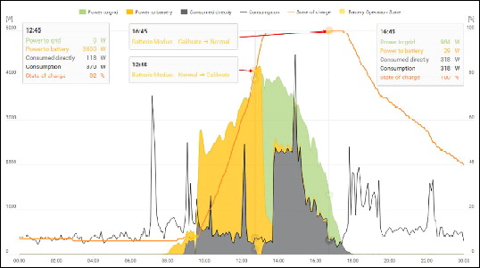
As during normal operation, the status "charging" (CHG) is shown on the battery display and the relevant charging current in ampere is displayed. If the charging current drops to below 0.3 A, 0 A is shown on the display, even though calibration charging continues.
In Fronius Solar.web, the SOC value for the entire battery is displayed. On the battery display, the SOC values of the individual battery modules can be viewed.
Fronius expressly points out that third-party batteries are not Fronius products and that Fronius is not a trader or distributor of these batteries. This means that Fronius accepts no liability for these batteries and cannot offer any kind of warranty.
The Fronius Symo Hybrid can be operated with an LG Chem type RESU7H(Type-R) or RESU10H(Type-R) high-voltage battery.
A Fronius Checkbox 500V is required to connect an LG battery to a hybrid inverter. Backup power mode is not possible when operating the LG Chem high-voltage battery.
Read this document and the Installation Instructions for the Fronius Symo Hybrid, the Fronius Checkbox 500V and the third-party battery before installation and commissioning.
All Fronius documents are available at the following address:
www.fronius.com/photovoltaics/infocentre/tech-support/how-to-install
The documentation for the LG Chem ResuH is enclosed with the third-party battery, or you can acquire it from the third-party manufacturer.
Danger due to DC voltage from the inverter and battery.
This can result in serious injury or death.
The Fronius Checkbox 500V must be installed in the system in accordance with the Installation Instructions.
Read and follow the "Fronius Checkbox 500V" Installation Instructions. The Installation Instructions are supplied with the Fronius Checkbox 500V.
Wire the "Third-party battery with Fronius Symo Hybrid and Fronius Checkbox 500V" in accordance with the Circuit Diagram. The Circuit Diagram is supplied with the Fronius Checkbox 500V.
Fronius expressly points out that third-party batteries are not Fronius products and that Fronius is not a trader or distributor of these batteries. This means that Fronius accepts no liability for these batteries and cannot offer any kind of warranty.
The Fronius Symo Hybrid can be operated with the following BYD Battery-Box Premium variants:Parallel operation of up to three BYD HVM batteries is possible in compliance with BYD specifications. A combination of three HVM 22.1 is not permitted.
* Note for systems with backup power switchover with Fronius Symo Hybrid and BYD Battery-Box Premium HVM 8.3:
If there is a power failure, there is no energy available from the PV system and the battery has a low state of charge (SOC typically < 20%), the system may no longer be able to switch to backup power mode.
Read this document and the Installation Instructions for the Fronius Symo Hybrid and the third-party battery before installation and commissioning.
All Fronius documents are available at the following address:
www.fronius.com/photovoltaics/infocentre/tech-support/how-to-install
The documentation for the BYD Battery-Box Premium is enclosed with the third-party battery, or you can acquire it from the third-party manufacturer.
IMPORTANT!
To ensure reliable operation with a BYD Battery-Box Premium HVM, the following switch-on sequence for the system must always be observed.

Set the DC disconnector to the "Off" switch position. Turn off the automatic circuit breaker.

Switch on the battery.

Switch on the automatic circuit breaker. Set the DC disconnector to the "On" switch position.

Item | Designation |
|---|---|
(1) | Switchable multifunction current interface Use the 2-pin mating connector supplied with the inverter to connect to the multifunction current interface. |
(2) | Floating switch contact with mating connector Max. 250 V AC / 4 A AC Pin 1 = NO contact (normally open) Use the mating connector supplied with the inverter to connect to the floating switch contact. |
(3) | System monitoring with WLAN antenna |
The inverter is fitted with the WLAN-enabled system monitoring and energy management unit (Fronius Datamanager) as standard.
Various functions are included with the Fronius system monitoring, such as:

No. | Function |
| ||||
|---|---|---|---|---|---|---|
(1) | IP switch |
| ||||
| Switch position A Access data for this access point: System monitoring can be accessed by:
|
| ||||
| Switch position B System monitoring uses an assigned IP address (factory setting: dynamic (DHCP)) |
| ||||
(2) | WLAN LED
| |||||
(3) | Solar.web connection LED
| |||||
(4) | Supply LED
| |||||
(5) | Connection LED
| |||||
(6) | LAN connection | |||||
(7) | I/Os  | |||||
Modbus RTU 2-wire (RS485):
| ||||||
Int./ext. power supply
| ||||||
Digital inputs: 0 - 3, 4 - 9 | ||||||
Digital outputs: 0 - 3 | ||||||
Switching capacity when power is supplied by an external power supply delivering min. 12.8 - max. 24 V DC (+ 20%), connected to Uint / Uext and GND: 1 A, 12.8 - 24 V DC (depending on external power supply) for each digital output | ||||||
The connection to the I/Os is established via the mating connector supplied. | ||||||
(8) | Antenna socket | |||||
(9) | Modbus termination switch (for Modbus RTU) Switch in "on" position: 120 ohm terminating resistor active  IMPORTANT! On an RS485 bus, the terminating resistor on the first and last device must be active. For a detailed description, see the Installation Instructions. | |||||

Item | Description |
|---|---|
(1) | Display |
| |
(2) | General status LED
|
(3) | Startup LED (orange)
|
(4) | Operating status LED (green)
|
| |
(5) | “Left/up” key |
(6) | “Down/right” key |
(7) | “Menu/Esc” key |
(8) | “Enter” key |
The keys operate capacitively. Exposure to water may impair their function. If necessary, wipe the keys dry with a cloth to ensure optimum functionality.
The display is supplied with power via the AC grid voltage and via the PV and battery side. Depending on the setting selected in the Setup menu, the display can be kept on all day.
The display on the inverter is not a calibrated measuring device.
A slight inaccuracy in comparison with the utility meter used by the energy company is intrinsic to the system. A calibrated meter will be needed to calculate the bills for the energy company.

 | |
Save symbol | |
Previous menu items | |
Currently selected menu item | |
Next menu items | |
Function key functions | |
|
|
| (*) | Scroll bar |
Save symbol – Appears briefly while the set values are being saved

| (1) | LCD display Provides information about the status of a module (charging/discharging, total voltage, total current strength, total remaining capacity, number of connected modules, remaining capacity of each module, voltage/temperature etc. of the cell block) |
| (2) | DISP switch Changes the information shown on the display |
| (3) | Indicator LED Normal status: Green Error: Flashing red |
| (4) | POWER ON/OFF switch POWER ON: Switches on battery modules and battery management module (operation) POWER OFF: Switches off battery modules and battery management module (power supply interrupted) |

| (1) | Indicator LED Normal status: Green Error: Flashing red |
Press the DISP key to display information.
Display switching diagram
Display overall status of system |  |
Display status of individual modules | |
| |
| |
| |
| |
 | Press and hold DISP key |
 | Press DISP key |
Nr.N. | Means the nth storage module |
"Overall" display | ||
 | ||
Display | Details | Display |
MODE | Charging/discharging and stop status | DIS: Discharging |
RSOC | Remaining system capacity | 0% - 100% |
I | Total system current strength | -999.9 A to +999.9 A |
V | Total system voltage | 0.0 V to +999.9 V |
|
|
|
"Connection" display | ||
 | ||
Display | Details | Display |
UNIT | Number of connected modules | 1 - 16 |
VER | Version | XXXX |
CON | Status of connected modules | In the above example, there are 6 connected modules (no. 00 - no. 05). |
|
|
|
"Status" display | ||
 | ||
Display | Details | Display |
M_NO | Number of modules displayed | 00 - 15 |
STAT | Module status | YX (Y: Current status, X: Previous status) |
|
|
|
"Mode, Current, SOC, Voltage" display | ||
 | ||
Display | Details | Display |
M_NO | Number of modules displayed | 00 - 15 |
RSOC | Remaining module capacity | 0% - 100% |
I | System module current strength | -999.9 A to +999.9 A |
V | System module voltage | 0.0 V to +999.9 V |
|
|
|
"Cell Temp., Cycle Count" display | ||
 | ||
Display | Details | Display |
M_NO | Number of modules displayed | 00 - 15 |
CYCL | Number of cycles | 0000 - 9999 |
T | Average temperature of all cells | -99.9 °C to +99.9 °C |
|
|
|
"Alarm bits" display | ||
 | ||
Display | Details | Display |
M_NO | Number of modules displayed | 00 - 15 |
ALRM | Module status | 8000 [Over Volt]: Overvoltage |
|
|
|
"Heatsink Temp" display | ||
 | ||
Display | Details | Display |
HEATSINK_TMP | Temperature of the heat sink | -40 °C to +119 °C |
COMM_QL | Internal communication quality | 0% - 100% |

Connection to Fronius Solar Battery | Connection to Fronius hybrid inverter |
|
 | ||
Factory settings:
S4 = 0x0 (hex) = 0000 (binary)
S5 = 0x0 (hex) = 0000 (binary)
S6 = 0x1 (hex) = 0001 (binary)
S7 = 0x4 (hex) = 0100 (binary)
 | RS485 terminal |
|
The data converter features 8 LEDs, the meaning of which is explained below:
Fronius Solar Battery | Fronius hybrid inverter |
|
|
Power LED |
| Green | Supply voltage on storage side |
LED 1/2/4/8 (Error No / Selected ID) |
| Green | General gateway error |
State LED |
| Red/green | General gateway error |
| State LED | Red/green | Inverter interface state |
| Power LED | Green | Inverter supply voltage |
"Power" LED(Fronius Solar Battery)
This LED is connected directly to the supply voltage of the 1st serial interface (electrical isolation is optionally available for this supply).
"1/2/4/8 (Error No / Selected ID)" LED
If these 4 LEDs and the "State" LED all light up steady red at the same time, the error number is indicated in binary format in accordance with the table in the "Troubleshooting" section.
"State" LED(Fronius Solar Battery)
Lights up green | Status OK |
Flashing green | Status OK |
Flashing green/red | Status OK |
Lights up red | General gateway error (see "Error No." LEDs) |
Flashing red | Data converter is in configuration/test mode |
"State" LED (Fronius hybrid inverter)
Lights up green | Initialised and started |
Flashing green | Initialised |
Flashing green/red | - |
Lights up red | General bus error (system error 10) |
Flashing red | Starts to flash straight after "BusStart" -> Initialisation failed |
"Power" LED (Fronius hybrid inverter)
This LED is connected directly to the supply voltage of the interface.
If two minutes pass without any button being pressed, the display backlighting switches off automatically and the inverter goes to the "NOW" menu item (assuming the display backlighting is set to AUTO).
The automatic selection of the "NOW" menu item can happen from any position on the menu level, unless the inverter was manually switched into the "Standby" operating mode.
After automatically selecting the "NOW" menu item, the current power of feeding in is displayed.
 | 1Press "ESC"  |
 | The display switches to the menu level. 2Using the "Left" or "Right" keys  select the desired menu item select the desired menu item3Press the "Enter" key  to select the desired menu item to select the desired menu item |
Output power (W) |
AC reactive power (VAr) |
Grid voltage (V) |
Output current (A) |
Grid frequency (Hz) |
Solar voltage (V) – Of U PV |
Solar current (A) – Of I PV |
Time Date |
Energy fed in (kWh / MWh) There may be discrepancies compared with values displayed on other measuring instruments because of differences in measuring methods. As far as the billing of the energy fed in is concerned, the only binding display values are those produced by the calibrated measuring instrument provided by the utility company. |
Max. output power (W) |
Yield Like the "Energy fed in" figure, the yield figure may also exhibit discrepancies compared with other measured values. The "Setup menu" section explains how to select a currency and charge rate. |
Max. grid voltage (V) |
Maximum solar voltage (V) |
Operating hours IMPORTANT! In order for the day and year values to be displayed correctly, the time must be set accurately. |
Alternative operating hours |
Manual activation / deactivation of Standby mode
key"STANDBY" and "ENTER" appear alternately on the display.
Standby mode is now active.
The Startup LED shows steady orange.
gridThe "Standby" menu item is displayed.
At the same time, the inverter enters the startup phase.
The operating state LED shows steady green when feeding energy into the grid has been resumed.
Activating / deactivating the WiFi Access Point. This is necessary for setting up or adjusting system monitoring using the Datamanager web interface, for example. If no Datamanager is detected by the inverter, [not available] is displayed
Setting range | WiFi Access Point |
| Activate WiFi AP? To activate the WiFi Access Point |
| WiFi Access Point The SS-ID (SS) and password (PW) are displayed. |
| Deactivate WiFi AP? To deactivate the WiFi Access Point |
| WiFi Access Point Displayed if there is no system monitoring present on the inverter. |
Status codes (state codes), the status of the inverter (e.g. feeding energy into the grid) or Energy Manager functions can be displayed using the floating switch contact (relay).
Setting range | Relay mode / Relay test / Switch-on point* / Switch-off point* |
* these are only shown if the "E-Manager" function has been activated under "Relay mode".
Relay mode
| |
Setting range | ALL / Permanent / GAF / OFF / ON / E-Manager |
Factory setting | ALL |
Alarm function: | ||
ALL / Permanent: | Switching the floating switch contact for permanent and temporary service codes (e.g. brief interruption to energy being fed into the grid, a service code occurs a certain number of times a day - can be adjusted in the "BASIC" menu) | |
GAF | As soon as GAF mode is selected, the relay is switched on. The relay opens as soon as the power stage set registers an error and goes from normally feeding energy into the grid to being in an error state. This means that the relay can be used for fail-safe functions. Application example | |
Active output: | ||
ON: | The floating NO contact is on all the time the inverter is in operation (as long as the display is not dark or is displaying something). | |
OFF: | The floating NO contact is off. | |
Energy Manager: | ||
E-Manager: | Further details on the "Energy Manager" function may be found in the "Energy Manager" section. | |
Relay test | ||
Switch-on point (only if "Energy Manager" function is activated) | ||
Factory setting | 1000 W |
Setting range | Set switch-off point up to the maximum nominal output of the inverter (W or kW) |
Switch-off point (only if "Energy Manager" function is activated) | |
Factory setting | 500 |
Setting range | 0 to the set switch-on point of the inverter (W or kW) |
The "Energy Manager" function can be used to activate the floating switch contact in such a way that it functions as an actuator.
Thus, a load that is connected to the floating switch contact can be controlled by specifying a switch-on or switch-off point that depends on the power of feeding in.
The floating switch contact is automatically switched off:
To activate the "Energy Manager" function, select "E-Manager" and press the "Enter" key. | |
 | When the floating NO contact is off (open contact) |
 | When the floating NO contact is on (closed contact) |
To deactivate the "Energy Manager" function, select a different function and press the "Enter" key.
Notes on setting up the switch-on and switch-off points
The interface of the energy management relay always uses the output power of the inverter as a reference point, although this will not necessarily match what is generated by the PV system in the case of the hybrid system.
If the difference between the switch-on and switch-off points is too small, or if there are fluctuations in effective power, the result may be multiple switching cycles
To avoid frequent switching on and off, the difference between the switch-on and switch-off points should be at least 100 - 200 W.
When choosing the switch-off point, the power consumption of the connected load should be taken into account.
When choosing the switch-on point, the weather conditions and anticipated insolation should also be taken into account.
Application example
Switch-on point = 2000 W, switch-off point = 1800 W
If the inverter is outputting 2000 W or above, then the floating switch contact on the inverter is switched on.
If the inverter output falls to below 1800 W, the floating switch contact is switched off.
Possible applications:
Operating a heat pump or an air-conditioning system using as much self-generated power as possible
Set the time, date and automatic changeover between summer and winter time
Setting range | Set time / Set date / Time display format / Date display format / Summer/winter time |
Set time
Set the time (hh:mm:ss or hh:mm am/pm – depending on the setting for the time display format)
Set date
Set the date (dd.mm.yyyy or mm/dd/yyyy - depending on the setting for the date display format)
Time display format | |
Setting range | 12hrs / 24hrs |
Factory setting | Depends on country setup |
Date display format | |
Setting range | mm/dd/yyyy / dd.mm.yy |
Factory setting | Depends on country setup |
Summer/winter time
Activate/deactivate automatic changeover between summer and winter time
Setting range | on / off |
Factory setting | on |
IMPORTANT! The time and date must be set accurately in order for the day and year values and for the day characteristic to be displayed correctly.
Setting range | Language / Contrast / Illumination |
Language
Set language for display
Setting range | German, English, French, Dutch, Italian, Spanish, Czech, Slovak, etc. |
Contrast
Set the contrast on the display
Setting range | 0 - 10 |
Factory setting | 5 |
Since the contrast is temperature-dependent, it may be necessary to adjust the setting under the "Contrast" menu item when the environmental conditions change.
Illumination
Initial setting for display illumination
The "Illumination" menu item only relates to the display backlighting.
Setting range | AUTO / ON / OFF |
Factory setting | AUTO |
AUTO: | The display backlighting is activated by pressing any key. If no key is pressed for 2 minutes, the display backlighting will go off again. | |
ON: | The display backlighting remains permanently on when the inverter is active. | |
OFF: | The display backlighting is permanently switched off. |
Setting range | Currency / Feed-in tariff |
Counter deviation / calibration | |
Currency | |
Setting range | 3 characters, A-Z |
Feed-in tariff | |
Setting range | 2 digits, 3 decimal places |
Factory setting | (depends on country setup) |
CO2 factor | |
To check that the fan is working correctly
Setting range | Test fan #1 / Test fan #2 (depending on the device) |
IMPORTANT! Nothing will show on the inverter display if the fan is working. The only way to check how the fan is working is by listening and feeling.
The inverter is pre-configured after commissioning has been completely carried out (e.g. using the Installation Wizard) according to the country setup.
The SETUP menu item allows the initial settings of the inverter to be changed easily to bring it in line, as closely as possible, with the preferences and requirements of the user.
IMPORTANT! As a result of software updates, you may find that your device has certain functions that are not described in these Operating Instructions, or vice versa. Certain illustrations may also differ slightly from the actual controls on your device, but these controls function in exactly the same way.
Entering the SETUP menu item | ||
 | | 1At the menu level, use the “Left” or “Right” keys to select the “SETUP” menu item |
| 2Press the "Enter" key | |
 | The first entry under the SETUP menu item is displayed: | |
Scrolling between the entries | ||
 |  | 3Use the "Up" and "Down" keys to move between the available entries |
Exiting an entry | ||
| | 4To exit a menu entry, press the "Back" key The menu level appears |
If no key is pressed for 2 minutes:
The available settings are displayed: |
| The first digit of a value to be set flashes: |
4Use the 'Up' or 'Down' buttons to select the desired setting 5Press the 'Enter' key to save and apply the setting. To discard the setting, press the 'Esc' key. | 4Use the 'Up' or 'Down' keys to select a value for the first digit 5Press "Enter" The second digit of the value flashes. 6Repeat steps 4 and 5 until ... the whole value to be set flashes. | |
| 7Press "Enter" 8Repeat steps 4 - 6 as required for units or other values that are to be set until the appropriate unit or the value flashes. 9Press the 'Enter' key to save and apply the changes. To discard the changes, press the 'Esc' key. | |
The currently selected menu item is displayed. |
| The currently selected menu item is displayed. |
 | | 1Select “Time / Date” from the Setup menu. |
| 2Press the “Enter” key. | |
|
|
 | An overview of the values that can be changed is displayed. | |
| 3Use the “Up” or “Down” keys to select “Set time”. | |
| 4Press the “Enter” key. |
 | The current time appears. | |
 | 5Use the “Up” and “Down” keys to select a value for the “tens” digit of the hour. | |
| 6Press the “Enter” key. |
 | The “units” digit for the hour will flash. | |
7Repeat steps 5 and 6 to set the “units” digit for the hour, for the minutes and for the seconds until... | ||
 | the set time starts flashing. | |
| 8Press the “Enter” key. | |
| The time is applied and the overview of values that can be changed is displayed. | |
 | 4Press the “Esc” key. |
| The “Time / Date” item on the Setup menu appears. | |
|
|
PV ins.
Insulation resistance of the photovoltaic system and the storage system
Ext. lim.
External power reduction in per cent e.g. specified by grid operator
U PV
Current PV voltage on the terminals even if the inverter is feeding in no power whatsoever
GVDPR
Grid voltage-dependent power reduction
Fan #1
Percentage of target output for fan
IMPORTANT! Due to the low level of insolation early in the morning and in the evening, the status codes STATE 306 (Power low) and STATE 307 (DC low) are displayed routinely at these times of day. These status codes do not indicate any kind of fault at this point in time.
The status of the most recent inverter fault can be displayed.
For displaying the settings that will be of relevance to a power supply company. The values shown will depend on the country setup or the device-specific settings of the inverter.
Display area | General / Country-specific setting / MPP tracker / Grid monitoring / Grid voltage limits / Grid frequency limits / Q-mode / AC power limit / AC voltage derating / Fault Ride Through |
General: | Device type |
Country-specific setting: | Setup Version Group |
MPP Tracker: | PV Tracker |
Grid monitoring: | GMTi GMTr ULL LLTrip |
Grid voltage limits: | UILmax UILmin |
Grid frequency limits: | FILmax FILmin |
Q-mode: | Current cos phi power factor setting |
AC power limit: | Max. P AC |
AC voltage derating: | Status GVDPRe GVDPRv Message |
Fault Ride Through: | Status – Default setting: OFF DB min – Default setting: 90% DB max - Default setting: 120% k-Fac. - Default setting: 0 |
Displays the version and serial numbers of the PC boards in the inverter (e.g. for service purposes)
Display area | Display / Display Software / Integrity Checksum / Memory Card / Memory Card #1 / Power Stage / Power Stage Software / EMI Filter / Power Stage #3 / Power Stage #4 |
The inverter has a key lock function.
When the key lock is active, the Setup menu is not accessible, i.e. the setup data cannot be changed accidentally (or maliciously).
The code 12321 has to be entered in order to activate / deactivate the key lock.
The inverter has a key lock function.
When the key lock is active, the Setup menu is not accessible, i.e. the setup data cannot be changed accidentally (or maliciously).
The code 12321 has to be entered in order to activate / deactivate the key lock.
1Press the "Menu" key | |
| The menu level appears. 2Press the unassigned "Menu / Esc" key 5 times  |
 | "Access Code" is displayed in the "CODE" menu; the first digit starts flashing. |
3Enter the code 12321: Use the "Plus" and "Minus" keys to select a value for the first digit of the code | |
4Press the "Enter" key |
 | The second digit flashes. |
5Repeat steps 3 and 4 for the second, third, fourth and fifth digits of the access code until... the selected code starts flashing. 6Press the "Enter" key |
 | "Setup Menu Lock" is displayed in the "LOCK" menu. |
7Use the "Plus" and "Minus" keys to turn the key lock on or off:ON = key lock is on (the Setup menu is not accessible) OFF = key lock is off (the Setup menu is accessible) | |
8Press the "Enter" key |
| 1Press the "Menu” buttonThe menu level appears. 2Press the unassigned "Menu / Esc" key 5 times |
| "Access Code" is displayed in the "CODE" menu; the first digit starts flashing. |
3Enter the code 22742: Use the "Plus" and "Minus" keys to select a value for the first digit of the code | |
4Press the "Enter" button |
 | The second digit flashes. |
5Repeat steps 3 and 4 for the second, third, fourth and fifth digits of the access code until... the selected code starts flashing. 6Press the "Enter" button |
The Basic menu appears.
to select the desired entry button | 1Press the "Menu” buttonThe menu level appears. 2Press the unassigned "Menu / Esc" key 5 times |
| "Access Code" is displayed in the "CODE" menu; the first digit starts flashing. |
3Enter the code 22742: Use the "Plus" and "Minus" keys to select a value for the first digit of the code | |
4Press the "Enter" button |
| The second digit flashes. |
5Repeat steps 3 and 4 for the second, third, fourth and fifth digits of the access code until... the selected code starts flashing. 6Press the "Enter" button |
The Basic menu appears.
to select the desired entry button The Basic menu is used to set the following parameters, which are important for installing and operating the inverter: |
MPP Tracker 1
|
Input signal
|
SMS / relay
|
Insulation setting
|
Temperature warning |
TOTAL Reset To reset the values to zero, press the "Enter" key. |
Fronius system monitoring is a networked datalogger.
The Fronius system monitoring web page provides a quick overview of the photovoltaic system.
It can be accessed via a web browser when there is a direct connection or – if configured to support an indirect connection – over the Internet.
If the feature is used in conjunction with Fronius Solar.web, current data and archive data can be accessed for a particular photovoltaic system via the Internet or the Fronius Solar.web App without the need for any laborious configuration work. Fronius system monitoring automatically sends the data to Fronius Solar.web.
You must have a suitable internet connection to enable data to be exchanged smoothly over the internet:
 download speed of at least 512 kBit/s and an
  upload speed of at least 256 kBit/s.
Even if these specifications are adhered to, there is still no guarantee that everything will run smoothly.
High error rates during transmission, variable reception conditions or transmission dropouts can all have a detrimental effect on the online functionality of Fronius system monitoring.
Fronius recommends testing any connections that meet the minimum requirements locally.
When using Fronius system monitoring, data is collated that must be transmitted over the internet.
The data volume must be calculated so that the correct internet connection is selected.
The data volume calculation below provides an overview of the data quantities involved when using Fronius system monitoring.
The data volume calculation depends on the number of connected devices in the system monitoring.
The table below provides an overview of the data volume for various configurations and time settings (INV = Fronius Symo Hybrid, SM = Smart Meter, BAT = battery module of the Fronius Solar Battery)
Data volume per day: | |||
|---|---|---|---|
Sent | Configuration | 5 min logging | 30 min logging |
Hourly | INV | 436 kB | 305 kB |
INV + SM | 659 kB | 349 kB | |
INV + SM + 3x BAT | 2198 kB | 605 kB | |
INV + SM + 4x BAT | 2556 kB | 659 kB | |
INV + SM + 5x BAT | 2958 kB | 750 kB | |
INV + SM + 6x BAT | 3306 kB | 775 kB | |
INV + SM + 7x BAT | 3485 kB | 838 kB | |
INV + SM + 8x BAT | 4160 kB | 920 kB | |
Daily | INV | 30 kB | 15 kB |
INV + SM | 55 kB | 20 kB | |
INV + SM + 3x BAT | 228 kB | 49 kB | |
INV + SM + 4x BAT | 262 kB | 53 kB | |
INV + SM + 5x BAT | 305 kB | 63 kB | |
INV + SM + 6x BAT | 344 kB | 68 kB | |
INV + SM + 7x BAT | 388 kB | 73 kB | |
INV + SM + 8x BAT | 426 kB | 83 kB | |
Data volume per month: | |||
|---|---|---|---|
Sent | Configuration | 5 min logging | 30 min logging |
Hourly | INV | 13 MB | 10 MB |
INV + SM | 20 MB | 11 MB | |
INV + SM + 3x BAT | 67 MB | 19 MB | |
INV + SM + 4x BAT | 78 MB | 20 MB | |
INV + SM + 5x BAT | 90 MB | 23 MB | |
INV + SM + 6x BAT | 101 MB | 24 MB | |
INV + SM + 7x BAT | 106 MB | 26 MB | |
INV + SM + 8x BAT | 126 MB | 28 MB | |
Daily | INV | 1 MB | 1 MB |
INV + SM | 2 MB | 1 MB | |
INV + SM + 3x BAT | 7 MB | 2 MB | |
INV + SM + 4x BAT | 8 MB | 2 MB | |
INV + SM + 5x BAT | 10 MB | 2 MB | |
INV + SM + 6x BAT | 11 MB | 3 MB | |
INV + SM + 7x BAT | 12 MB | 3 MB | |
INV + SM + 8x BAT | 13 MB | 3 MB | |
A data volume of approx. 500 kB per hour is required to view the system on Fronius Solar.web or the Fronius Solar.web App.
A certain data volume is also required to update the Fronius system monitoring firmware. This data volume depends on the size of the update package and therefore cannot be considered in the advance data volume calculation.
If data is sent via a third-party service (e.g. push service), a large quantity of data may be involved.
IMPORTANT! Fronius recommends a flat rate data connection to avoid high connection charges.
NOTE! Knowledge of networking systems is required in order to configure Fronius system monitoring for the network.
If you are integrating Fronius system monitoring into an existing network, you must adapt the address settings in line with the network.
e.g.: Network address space = 192.168.1.x, subnet mask = 255.255.255.0
If you want Fronius system monitoring to send service messages or to transmit data to Fronius Solar.web, you must enter a gateway address and a DNS server address. Fronius system monitoring uses the gateway address for the purpose of establishing an Internet connection. An example of a suitable gateway address would be the IP address of the DSL router.
IMPORTANT!
DSL routers usually allow data to be sent over the internet and so do not normally have to be configured for this purpose.
Server addresses for data transferIf existing firewall rules block the connection to the Fronius system monitoring function, the following firewall rules must be added:
| 49049/UDP | 80/TCP *) |
Sending of service messages | x | - |
Ability to connect to Datamanager via Fronius Solar.web | x | - |
Ability to connect to Datamanager via Fronius Solar.access or Fronius Solar.service | - | x |
Ability to access the Datamanager web page | - | x |
Configure the firewall so that data can be sent from the Fronius system monitoring IP address to port 49049/UDP of "fdmp.solarweb.com".
*) We recommend only allowing access to the web interface of the Fronius system monitoring function from secure networks. If internet access is absolutely necessary (e.g. for service purposes within a defined time period), configure the network router in such a way that requests for any external port are redirected to port 80/TCP.
Caution - the inverter will therefore be visible on the internet and at will be at an increased risk of network attacks.
An Internet connection is required if you want to use Fronius Solar.web or to send service messages.
Fronius system monitoring is not capable of connecting to the Internet on its own. In the case of a DSL connection, a router has to establish the Internet connection.
Danger from incorrect operation
This can result in severe personal injury and damage to property.
Do not use the functions described here until you have fully read and understood the Operating Instructions of every system component:
Do not use the functions described here until you have read and understood all the safety rules.
IMPORTANT! Knowledge of networking systems is required in order to install Fronius system monitoring.
IMPORTANT! In order to establish a connection to Fronius system monitoring, the end device in question (e.g. laptop, tablet, etc.) must be set up as follows:

The inverter establishes the WLAN access point. The WLAN access point remains open for 1 hour.
| Installation using a web browser 2Connect the end device to the WLAN access point SSID = FRONIUS_239.xxxxx (4-8 digits)
3Enter the following in the browser: http://datamanager or 192.168.250.181 (IP address for WLAN connection) or 169.254.0.180 (IP address for LAN connection) |
The Setup wizard start page is displayed.
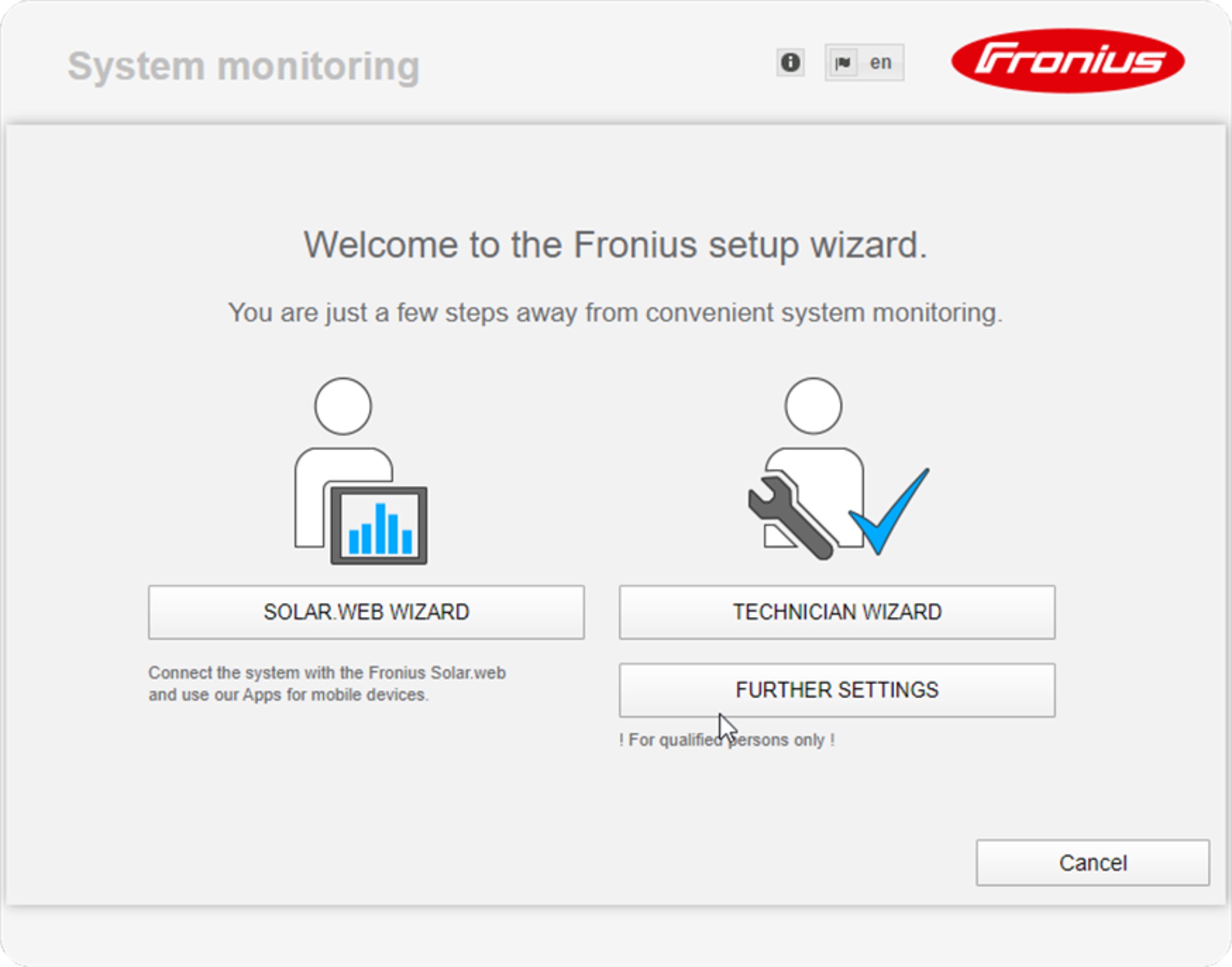
If you run the technician wizard, always remember to make a note of the assigned service password. This service password is required to enter settings in the "System overview" and "DNO Editor" menus as well as for advanced battery settings.
If the technician wizard is not run, no specifications regarding power reduction are set and hybrid mode is not possible (charging and discharging of the battery)
Danger of deep discharge of an unactivated battery
This may result in permanent damage to the battery.
The Solar Web wizard needs to be run in order to activate the battery and, if necessary, the Smart Meter.
The Fronius Solar.start homepage
or
the Fronius system monitoring web page is displayed.
The technician wizard consists of 5 steps:
1. General
General system data (e.g. system name) is entered here
2. Service password
Enter (and make a note of) the service password.
3. IO assignment
Settings for the IO interface are entered (see also General for IO assignment on page (→))
4. System overview
Settings for the entire PV system are entered (see also System overview on page (→))
5. Dynamic power
Settings for dynamic power reduction are entered (see also DNO Editor – Dynamic power reduction on page (→))
Once you have worked your way through the technician wizard, an automatic process is triggered to calibrate all the components. This involves charging the Fronius Solar Battery fully. After that, the system automatically starts in the set operating mode.
This calibration charging process is also performed automatically during actual operation after a number of charging and discharging cycles. When this calibration charge is performed depends on a number of different factors, such as the average state of charge or the energy throughput through the battery. The time can therefore vary depending on the time of year as well.
If the "permit battery charging from DNO grid" setting is deactivated, this calibration charging process relies exclusively on energy from the photovoltaic system when operating under normal conditions. Depending on the insolation conditions and size of the systems concerned, the charging process can take a very long time.
If the "permit battery charging from DNO grid" setting is activated, the calibration charging process is performed by drawing a constant current from the photovoltaic system and the DNO grid.
IMPORTANT! The automatic process for fully charging the battery may result in energy being drawn from the DNO grid. The process can take several hours and cannot be aborted.
Danger from immediate inverter operation in backup power mode without a connection to the grid having been previously established.
During grid-connected operation, the inverter recognises and stores the direction of phase rotation in the household network.
Without a grid connection, no information is available regarding the direction of rotation and the inverter feeds energy with a default direction of rotation.
This can cause the three-phase consumers in the household network to experience errors.
Backup power mode should be tested once it has been installed and set up for the first time. A battery state of charge of over 30% is recommended when in test mode.
A description of how to perform the test operation can be found in the chapter "Backup power checklist" of the document "Fronius Energy Package - Examples of backup power switchover".
A connection to Fronius system monitoring via a web browser is the ideal choice if there are lots of PC users who need to access the latest system values over the same LAN (e.g. company networks, schools, etc.).
The Fronius system monitoring web page shows the current power flow in the hybrid system.
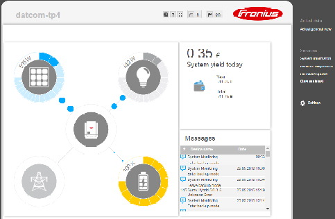
Archive and current data for a photovoltaic system can be accessed from anywhere in the world (provided that you have Internet access) by setting up a connection to Fronius system monitoring via the Internet and Fronius Solar.web.
With this setup, you can also invite other users to view the photovoltaic system data as guests and you can compare several systems with one another.
Fronius system monitoring is connected to the Internet (e.g. via a DSL router). Fronius system monitoring logs into Fronius Solar.web at regular intervals and sends the saved data on a daily basis.
Fronius Solar.web can actively make contact with Fronius system monitoring, e.g. for the purpose of displaying up-to-date data.
To use Fronius Solar.web for the purpose of accessing current data and archive data recorded by Fronius system monitoring, proceed as follows:
The Fronius system monitoring web page shows the following data:
(1) | Additional settings |
(2) | System overview: displays the current power flow on the hybrid system |
(3) | System yield overview |
(4) | Overview of recent status codes |
(5) | System information, network diagnostics, firmware update |
(6) | The Settings menu |
When you click "Settings", the Settings menu appears on the Fronius system monitoring web page.
The "Settings" menu is where you configure Fronius system monitoring.
Setting and viewing "General" menu items
On the Fronius system monitoring web page, the following additional setting options are available on the top right-hand side:

 | System information: |
 | Help:
|
 | Expand contents: |
 | Display messages |
 | Language: The Fronius system monitoring web page is either displayed in the same language as the current browser or in the language that was last selected. |
Die Seite Systeminformationen enthält verschiedene Informationen zum System.
Zusätzlich gibt es folgende Schaltflächen:WICHTIG! Wird der Datamanager (Anlagenüberwachung) auf Werkseinstellungen zurückgesetzt, müssen die Zeit- und Datumseinstellungen kontrolliert werden.
Die Seite Systeminformationen enthält verschiedene Informationen zum System.
Zusätzlich gibt es folgende Schaltflächen:WICHTIG! Wird der Datamanager (Anlagenüberwachung) auf Werkseinstellungen zurückgesetzt, müssen die Zeit- und Datumseinstellungen kontrolliert werden.
Unter Services / Netzwerkdiagnose befinden sich Funktionen, die zur Diagnose und Behebung von Netzwerk-Problemen hilfreich sind. Es können Ping- und Traceroute-Befehle ausgeführt werden.
Ping-Befehl
mit einem Ping-Befehl kann überprüft werden, ob ein Host erreichbar ist und wieviel Zeit die Datenübertragung in Anspruch nimmt.
Traceroute-Befehl
mit einem Traceroute-Befehl kann ermittelt werden, über welche Zwischenstationen Daten zum Host übermittelt werden.
The firmware of the Fronius system monitoring datalogger can be updated under Services / Firmware update. A firmware update can be performed via a LAN or over the Web.
The firmware of the Fronius system monitoring datalogger can be updated under Services / Firmware update. A firmware update can be performed via a LAN or over the Web.
IMPORTANT! An Internet connection is required to use the “Automatic update search” function.
If the “Automatic update search” (1) option is activated, Fronius system monitoring automatically searches for updates once a day. If new updates are available, a corresponding message is displayed alongside the additional setting options on the Fronius system monitoring web page.
Ist die Auswahlmöglichkeit automatisch nach Updates suchen deaktiviert, werden Updates nicht automatisch gesucht.
If the connection to the server fails:
IMPORTANT! If a proxy server is being used to establish the Internet connection:
You can access and run the setup wizard again by selecting "Open wizards".
SOLAR WEB WIZARD
For connecting the system to Fronius Solar.web and Fronius apps for mobile devices
TECHNICIAN WIZARD (for trained personnel or specialists only)
For system settings
FURTHER SETTINGS (for trained personnel or specialists only)
All settings for Fronius system monitoring. Click the "SOLAR WEB WIZARD" button to return to the original page.
Unter Vergütung kann der Verrechnungssatz pro kWh, die Währung und die Bezugskosten pro kWh für die Errechnung des Ertrages eingegeben werden. Der Ertrag wird in der aktuellen Gesamtansicht angezeigt.
Unter Systemzeit kann das Datum, die Stunde und die Minuten eingegeben werden.
Durch Klicken der Schaltfläche Synchronisieren wird die in den Eingabefeldern der Webseite des Datamanagers angezeigte Zeit an die Zeit des Betriebssystemes angepasst.
Zum Übernehmen der Zeit Schaltfläche Übernehmen / Speichern  klicken.
Unter Zeitzonen Einstellungen kann die Region und der Ort für die Zeitzone eingestellt werden.
Die Eingabe der mit * gekennzeichneten Felder ist obligatorisch.
Unter Vergütung kann der Verrechnungssatz pro kWh, die Währung und die Bezugskosten pro kWh für die Errechnung des Ertrages eingegeben werden. Der Ertrag wird in der aktuellen Gesamtansicht angezeigt.
Unter Systemzeit kann das Datum, die Stunde und die Minuten eingegeben werden.
Durch Klicken der Schaltfläche Synchronisieren wird die in den Eingabefeldern der Webseite des Datamanagers angezeigte Zeit an die Zeit des Betriebssystemes angepasst.
Zum Übernehmen der Zeit Schaltfläche Übernehmen / Speichern klicken.
Unter Zeitzonen Einstellungen kann die Region und der Ort für die Zeitzone eingestellt werden.
Die Eingabe der mit * gekennzeichneten Felder ist obligatorisch.
Access to Fronius system monitoring is controlled by assigning passwords.
There are 3 different types of password available for this purpose:
Access to Fronius system monitoring is controlled by assigning passwords.
There are 3 different types of password available for this purpose:
Administrator password
User name = admin
The administrator password is set during the commissioning process and grants the user read access and the right to change settings. The user can open the Settings menu and enter all settings apart from those for “DNO Editor” and "Meter".
If an administrator password has been set, the user must enter the user name and password in order to open the Settings menu.
Service password
User name = service
The service password is usually assigned by the service technician or system installer when running the Setup wizard and it provides access to system-specific parameters. The service password is required to modify meter and DNO Editor settings. The "Meter" and "DNO Editor" menu items cannot be accessed unless a service password has been assigned.
User password
When the 'Protect your system monitoring from unauthorized read access' selection box is checked, the user password is displayed, user name = user.
If a user password has been assigned, the user only has read permissions. The user is not able to open the “Settings” menu.
If a user password is assigned, the user is required to enter the user name and password whenever they want to establish a connection.

Die gefundenen Netzwerke werden angezeigt.
Mit einem Klick auf den Refresh-Button  wird eine erneute Suche nach verfügbaren WLAN-Netzwerken ausgeführt.
Versteckte Netzwerke können über das Menü WLAN Einstellungen > WLAN hinzufügen hinzugefügt werden.
Schaltfläche Einrichten - zum Speichern eines ausgewählten WLAN-Netzwerkes.
Nach Klicken der Schaltfläche öffnet sich das Fenster „WLAN Verbindung“
Schaltfläche Entfernen - zum Löschen eines gespeicherten WLAN-Netzwerkes.
Schaltfläche WLAN IP konfigurieren - Nach Klicken der Schaltfläche öffnet sich das Fenster IP konfigurieren mit den gleichen Einstellmöglichkeiten wie bei einer LAN-Verbindung.
Schaltfläche Verbinden via WPS - zum Verbinden ins WLAN via WPS ohne WLAN Passwort:
1. WPS am WLAN Router aktivieren (siehe Dokumentation des WLAN Routers)
2. Schaltfläche Verbinden via WPS klicken
3. Die WLAN Verbindung wird automatisch hergestellt
Die gefundenen Netzwerke werden angezeigt.
Mit einem Klick auf den Refresh-Button wird eine erneute Suche nach verfügbaren WLAN-Netzwerken ausgeführt.
Versteckte Netzwerke können über das Menü WLAN Einstellungen > WLAN hinzufügen hinzugefügt werden.
Schaltfläche Einrichten - zum Speichern eines ausgewählten WLAN-Netzwerkes.
Nach Klicken der Schaltfläche öffnet sich das Fenster „WLAN Verbindung“
Schaltfläche Entfernen - zum Löschen eines gespeicherten WLAN-Netzwerkes.
Schaltfläche WLAN IP konfigurieren - Nach Klicken der Schaltfläche öffnet sich das Fenster IP konfigurieren mit den gleichen Einstellmöglichkeiten wie bei einer LAN-Verbindung.
Schaltfläche Verbinden via WPS - zum Verbinden ins WLAN via WPS ohne WLAN Passwort:
1. WPS am WLAN Router aktivieren (siehe Dokumentation des WLAN Routers)
2. Schaltfläche Verbinden via WPS klicken
3. Die WLAN Verbindung wird automatisch hergestellt


The Datamanager (system monitoring) serves as an access point. A PC or smart device connects directly with the Datamanager (system monitoring). It is not possible to connect to the internet.
Über den Menüpunkt Fronius Solar.web kann eine direkte Verbindung zu Fronius Solar.web aufgebaut werden.
Die Auswahl des Speicherintervalls bei den Feldern Abfragezyklus Wechselrichter und Abfragezyklus Fronius Sensor Cards hat Auswirkungen auf die benötigte Speicherkapazität.
Schaltfläche Solar.web registrieren - durch Klicken der Schaltfläche wird die Fronius Solar.web Startseite geöffnet, für Fronius Solar.web relevante Daten werden automatisch mitgeschickt.
Cloud Control
Ein virtuelles Kraftwerk ist ein Zusammenschaltung mehrerer Erzeuger zu einem Verbund. Dieser Verbund kann über die Cloud-Steuerung per Internet gesteuert werden. Eine aktive Internetverbindung des Wechselrichters ist Voraussetzung dafür. Es werden Daten der Anlage übermittelt.
Wenn die Funktion Cloud-Steuerung für Anforderungen des Netzbetreibers/Energieversorgers zulassen aktiviert ist (service-Zugang erforderlich), ist die Funktion Cloud-Steuerung für virtuelle Kraftwerke zulassen automatisch aktiviert und kann nicht deaktiviert werden.
Die Funktion Cloud-Steuerung für Anforderungen des Netzbetreibers/Energieversorgers zulassen kann für den ordnungsgemäßen Betrieb der Anlage verpflichtend sein.
This menu item allows you to configure the properties of the inverter's individual inputs and outputs (I/O). You can only select those settings that are supported by the system concerned (which are determined by the functionality of the system and how it has been configured).
An active output that has not been assigned (is "free") remains active until the inverter is restarted. The status of an output only changes in the event of new specifications for assigned services.
Function | Description | Default pin |
|---|---|---|
Grant emergency power locking | Output, triggers disconnection from the mains (protection) | 0 |
Feedback locking (optional) | Input, gives feedback on whether locking is active | 5 |
Emergency power request | Input, triggers emergency power mode | 4 |
Emergency power mode is enabled by configuring these parameters.
Hier können bis zu vier Pins für das Lastmanagement ausgewählt werden. Weitere Einstellungen für das Lastmanagement sind im Menüpunkt Lastmanagement verfügbar.
Default-Pin: 1
Hier können die Pins für die IO-Steuerung eingestellt werden. Weitere Einstellungen sind im Menü EVU-Editor > IO-Steuerung möglich.
IO-Steuerung | Default-Pin | IO-Steuerung | Default-Pin |
|---|---|---|---|
IO-Steuerung 1 (optional) | 2 | IO-Steuerung 6 (optional) | 7 |
IO-Steuerung 2 (optional) | 3 | IO-Steuerung 7 (optional) | 8 |
IO-Steuerung 3 (optional) | 4 | IO-Steuerung 8 (optional) | 9 |
IO-Steuerung 4 (optional) | 5 | IO-Steuerung Rückmeldung | 0 |
IO-Steuerung 5 (optional) | 6 |
Demand Response Modes für Australien
Hier können die Pins für eine Steuerung via DRM eingestellt werden:
WICHTIG! Für eine Steuerung des Wechselrichters via DRM ist ein Fronius DRM Interface (Artikelnummer 4,240,005) im Wechselrichter erforderlich. | |
 | http://www.fronius.com/QR-link/4204102292 |
Mode | Beschreibung | Information | Default-Pin |
|---|---|---|---|
DRM0 | Wechselrichter trennt sich vom Netz | Netzrelais öffnen | |
REF GEN | geschlossen | FDI | |
COM LOAD | geschlossen | FDI | |
DRM1 | -Pnom ≤ 0 % ohne Trennung vom Netz | begrenzt die Wirkleistungs-Aufnahme | 6 |
DRM2 | -Pnom ≤ 50 % | begrenzt die Wirkleistungs-Aufnahme | 7 |
DRM3 | -Pnom ≤ 75 % & +Qrel* ≥ 0 % | begrenzt die Wirkleistungs-Aufnahme | 8 |
DRM4 | -Pnom ≤ 100 % | Normalbetrieb ohne Begrenzung | 9 |
DRM5 | +Pnom ≤ 0 % ohne Trennung vom Netz | begrenzt die Wirkleistungs-Abgabe | 6 |
DRM6 | +Pnom ≤ 50 % | begrenzt die Wirkleistungs-Abgabe | 7 |
DRM7 | +Pnom ≤ 75 % & -Qrel* ≥ 0 % | begrenzt die Wirkleistungs-Abgabe | 8 |
DRM8 | +Pnom ≤ 100 % | Normalbetrieb ohne Begrenzung | 9 |
|
|
|
|
FDI | am Fronius DRM Interface |
|
|
* | Die Werte für Qrel können im Menüpunkt EVU Editor eingestellt werden. | ||
Die Fernsteuerbarkeit der Wechselrichter bezieht sich immer auf die nominale Geräteleistung.
WICHTIG! Ist am Datamanager keine DRM Steuerung (DRED) angeschlossen und die Funktion AUS - Demand Response Mode (DRM) ist aktiviert, wechselt der Wechselrichter in den Standby-Betrieb.
The pin for activating the energy storage device can be selected here. This setting only needs to be made for certain energy storage devices.
If an energy storage device pin is set, then emergency power pins cannot be configured.
Energy management controlling priorities
If additional components (e.g. battery, Ohmpilot) are available in the system, the priorities can be set here. Devices with a higher priority are activated first, followed by the others if surplus energy is available.
Load management
Up to four different load management rules can be defined. If the thresholds are the same, the rules are activated in sequence. During deactivation, it is the other way round; the last IO switched on is the first to be switched off. If the thresholds are different, the IO with the lowest threshold is switched on first, followed by the one with the second lowest threshold and so on.
IOs which are controlled through the power produced are always at an advantage over the battery and Ohmpilot. This means an IO can switch itself on, resulting in the battery no longer being charged or the Ohmpilot no longer being activated
An IO is only activated or deactivated after 60 sec.
ControlEnergy management controlling priorities
If additional components (e.g. battery, Ohmpilot) are available in the system, the priorities can be set here. Devices with a higher priority are activated first, followed by the others if surplus energy is available.
Load management
Up to four different load management rules can be defined. If the thresholds are the same, the rules are activated in sequence. During deactivation, it is the other way round; the last IO switched on is the first to be switched off. If the thresholds are different, the IO with the lowest threshold is switched on first, followed by the one with the second lowest threshold and so on.
IOs which are controlled through the power produced are always at an advantage over the battery and Ohmpilot. This means an IO can switch itself on, resulting in the battery no longer being charged or the Ohmpilot no longer being activated
An IO is only activated or deactivated after 60 sec.
ControlMit Hilfe dieser Funktion können Aktuell- und Log-Daten in unterschiedlichen Formaten oder mit unterschiedlichen Protokollen auf einen externen Server exportiert werden.
Weitere Informationen zur Push Service Funktion finden Sie in folgender Bedienungsanleitung:

http://www.fronius.com/QR-link/4204102152
42,0410,2152
Fronius Push Service
Mit Hilfe dieser Funktion können Aktuell- und Log-Daten in unterschiedlichen Formaten oder mit unterschiedlichen Protokollen auf einen externen Server exportiert werden.
Weitere Informationen zur Push Service Funktion finden Sie in folgender Bedienungsanleitung:
http://www.fronius.com/QR-link/4204102152
42,0410,2152
Fronius Push Service
With a web browser, you can use the Fronius system monitoring web page to make settings for the Modbus connection that are not accessible via the Modbus protocol.
With a web browser, you can use the Fronius system monitoring web page to make settings for the Modbus connection that are not accessible via the Modbus protocol.
Weitere Informationen zur Modbus-Funktion finden Sie in folgenden Bedienungsanleitungen:
 | http://www.fronius.com/QR-link/4204102049 42,0410,2049 | |||
 | http://www.fronius.com/QR-link/4204102108 42,0410,2108 | |||
"Exporting data via Modbus" on "off"
If exporting data via Modbus is deactivated, transmitted control commands sent over Modbus to the inverters, e.g. no power reduction or no reactive power specification, are reset.
"Exporting data via Modbus" on "tcp"
If exporting data via Modbus is deactivated, transmitted control commands sent over Modbus to the inverters, e.g. no power reduction or no reactive power specification, are reset.
"Modbus port" field - Number of the TCP port that is to be used for Modbus communication. Initial setting: 502. Port 80 cannot be used for this.
"String Control Address Offset" field - Offset value for addressing the Fronius String Controls via Modbus.
"Sunspec Model Type" - For selecting the data type of data models for inverters and of data models for energy meters
"float" - Display as floating point numbers
SunSpec Inverter Model I111, I112 or I113
SunSpec Meter Model M211, M212 or M213
"int+SF" - Display as whole numbers with scaling factors
SunSpec Inverter Model I101, I102 or I103
SunSpec Meter Model M201, M202 or M203
IMPORTANT! Since the various models have different numbers of registers, switching the data type also changes the register addresses for all subsequent models.
"Demo mode" - Demo mode is used to implement or validate a Modbus master. It enables inverter, energy meter and Fronius string control data to be read out, even if no device is actually connected or active. The same data is always returned for all registers.
"Inverter control via Modbus""Control priorities"
The control priorities define which service takes priority during inverter control.
1 = highest priority, 3 = lowest priority
The control priorities can only be changed under the "DNO EDITOR" menu item.
Die Option Steuerung einschränken ist nur beim Übertragungsprotokollen tcp verfügbar.
Sie dient dazu Wechselrichter-Steuerungsbefehle durch Unbefugte zu verhindern, indem die Steuerung nur für bestimmte Geräte erlaubt wird.
Feld IP-Adresse
Um die Wechselrichter-Steuerung auf ein oder mehrere Geräte zu beschränken, werden in diesem Feld die IP-Adressen jener Geräte eingetragen, die Befehle an den Fronius Datamanager senden dürfen. Mehrere Einträge werden durch Beistriche getrennt.
Own consumption optimization
The Fronius hybrid inverter always controls the system by adjusting it in line with the target value set at the metering point. In the "automatic" operating mode (factory setting), an adjustment is made to 0 W at the feed-in point (maximum self-consumption).
The self-consumption optimisation has lower priority than the battery control specifications.
Own consumption optimization
Option for selecting automatic or manual self-consumption optimisation
Target value at the metering point
If you opt for "manual" under "Own consumption optimization", you can select the target value at the metering point and choose between "Consumption" and "Feed-in" here
Backup power
 Operating mode
"Automatic" or "Off" can be selected for backup power mode.
The backup power functionality can only be activated once the required IO assignments have been configured for backup power. The meter must be installed at the feed-in point and configured.
Residual battery capacity
Energy is drawn from the battery in grid-connected operation until this residual battery capacity is reached. In backup power mode without a grid, the battery is always discharged to the minimum SOC preset by the battery manufacturer.
SOC warning level
A warning is output when the residual capacity of the battery specified here is reached in backup power mode.
Own consumption optimization
The Fronius hybrid inverter always controls the system by adjusting it in line with the target value set at the metering point. In the "automatic" operating mode (factory setting), an adjustment is made to 0 W at the feed-in point (maximum self-consumption).
The self-consumption optimisation has lower priority than the battery control specifications.
Own consumption optimization
Option for selecting automatic or manual self-consumption optimisation
Target value at the metering point
If you opt for "manual" under "Own consumption optimization", you can select the target value at the metering point and choose between "Consumption" and "Feed-in" here
Backup power
Operating mode
"Automatic" or "Off" can be selected for backup power mode.
The backup power functionality can only be activated once the required IO assignments have been configured for backup power. The meter must be installed at the feed-in point and configured.
Residual battery capacity
Energy is drawn from the battery in grid-connected operation until this residual battery capacity is reached. In backup power mode without a grid, the battery is always discharged to the minimum SOC preset by the battery manufacturer.
SOC warning level
A warning is output when the residual capacity of the battery specified here is reached in backup power mode.
These examples illustrate possible energy flows. Efficiency values have not been taken into account.
Battery system example |
| |
PV system to Fronius Symo Hybrid: | 1000 W |
|
Household consumption: | 500 W |
|
Target value set at feed-in point: | 0 W |
|
|
|
|
Power to the battery: | 500 W |
|
Power output (AC) by inverter: | 500 W |
|
Energy fed into the public grid: | 0 W |
|
 | ||
|
|
|
Example involving battery system without photovoltaics but with a second producer within the home | ||
Second producer in home network: | 2000 W |
|
Household consumption: | 500 W |
|
Target value set at feed-in point: | 0 W |
|
|
|
|
Power to the battery: | 1500 W |
|
Power consumed (AC) by inverter: | 1500 W |
|
Energy fed into the public grid: | 0 W |
|
 | ||
|
|
|
Example involving battery system with a second producer within the home | ||
PV system to Fronius Symo Hybrid: | 1000 W |
|
Second producer in home network: | 2000 W |
|
Household consumption: | 500 W |
|
Target value set at feed-in point: | 0 W |
|
|
|
|
Power to the battery: | 2500 W |
|
Power consumed (AC) by inverter: | 1500 W |
|
Energy fed into the public grid: | 0 W |
|
 | ||
|
|
|
Example involving battery system plus a second producer within the home (with AC max. limiting) | ||
PV system to Fronius Symo Hybrid: | 1000 W |
|
Second producer in home network: | 2000 W |
|
Household consumption: | 500 W |
|
Target value set at feed-in point: | 0 W |
|
Max. AC power consumption limited to: | 1000 W |
|
|
|
|
Power to the battery: | 2000 W |
|
Power consumed (AC) by inverter: | 1000 W |
|
Energy fed into the public grid: | 500 W |
|
 | ||
Battery charging/discharging limits:
The battery charging / discharging limits can be set "automatically" or "manually".
If they are set automatically, suitable values are selected for the battery.
If they are set manually, values can be set in the "Max SoC" (maximum state of charge) and "Min SoC" (minimum state of charge) fields. The range of values that can be set differs depending on the battery. In backup power mode without a grid, the set values are not taken into account.
IMPORTANT! The settings must be agreed with the battery manufacturer! Fronius accepts no liability for damage to third-party batteries.
Battery control specification:
Using the time-dependent battery control, it is possible to prevent or restrict the charging/discharging and to specify a defined value for charging/discharging.
The battery is affected by external factors, such as calibration charging, permitting AC charging, inverter power limitation, control parameters via Modbus or self-consumption optimisation. The battery control specifications have the second lowest priority, following the self-consumption optimization, and it may be the case that these are not fulfilled due to other specifications.
Without any battery control specifications, optimization is performed to establish the best possible degree of self-consumption. Self-consumption decreases when battery control specifications are defined.
The following values can be selected in the column "regulation":The day and time window in which this regulation applies is defined in the columns "Day of the week" and "Time window". It is not possible to define a time window over midnight.
Example: Two entries are needed to set a parameter of 22:00 to 06:00: '22:00 - 24:00' and '00:00 - 06:00'.
Examples for the battery control specifications can be found in the following chapter.
Calibration charging (only for Fronius Solar Battery)
At regular intervals, the Fronius hybrid inverter automatically charges the Fronius Solar Battery until it is full for the purpose of calibrating all the components. This process can be started manually here.
IMPORTANT! When calibration charging is activated, normal operation is interrupted and the system may draw energy from the distribution network operator's grid. The process can take several hours and cannot be aborted.
Once calibration is complete, the system automatically reverts to the operating mode that was set originally.
This calibration charging process is also performed automatically during actual operation after a number of charging and discharging cycles.
If the "permit battery charging from DNO grid" setting is deactivated, this calibration charging process relies exclusively on energy from the photovoltaic system. Depending on the insolation conditions and size of the systems concerned, the charging process can take a very long time.
If the "permit battery charging from DNO grid" setting is activated, the calibration charging process is performed by drawing a constant current from the photovoltaic system and the distribution network operator's grid.
A parameter always consists of one of the four limitations above and the times during which the limitation applies. At any one time, none, one or a maximum of two limitations that are compatible with one another can be active.
Maximum charging and discharging limits | ||||||||||||
Discharging limit |
| Discharge / charge |
|
| Charging limit | |||||||
|
|
|
|
|
|
|
|
|
|
|
| |
|
|
|
|
|
|
|
|
|
|
|
| |
|
|
|
|
|
|
|
|
|
|
|
| |
|
|
| Max. discharging |
|
| Max. charging |
|
|
| |||
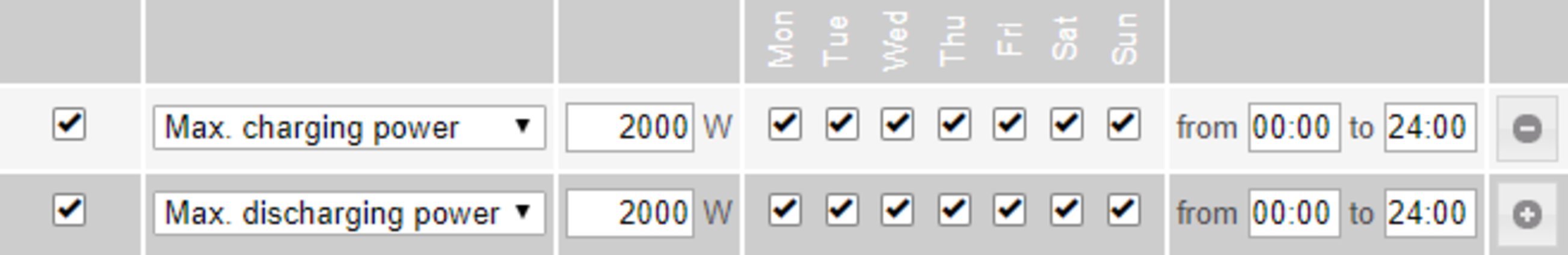 | ||||||||||||
|
|
|
|
|
|
|
|
|
|
|
| |
Specifying the charging range |
| |||||||||||
Discharging limit |
| Discharge / charge |
|
| Charging limit | |||||||
|
|
|
|
|
|
|
|
|
|
|
| |
|
|
|
|
|
|
|
|
|
|
|
| |
|
|
|
|
|
|
|
|
|
|
|
| |
|
|
|
|
| Min. charging | Max. charging |
| |||||
 | ||||||||||||
|
|
|
|
|
|
|
|
|
|
|
| |
Specifying the discharging range |
| |||||||||||
Discharging limit |
| Discharge / charge |
|
| Charging limit | |||||||
|
|
|
|
|
|
|
|
|
|
|
| |
|
|
|
|
|
|
|
|
|
|
|
| |
|
|
|
|
|
|
|
|
|
|
|
| |
| Max. discharging | Min. discharging |
|
|
|
| ||||||
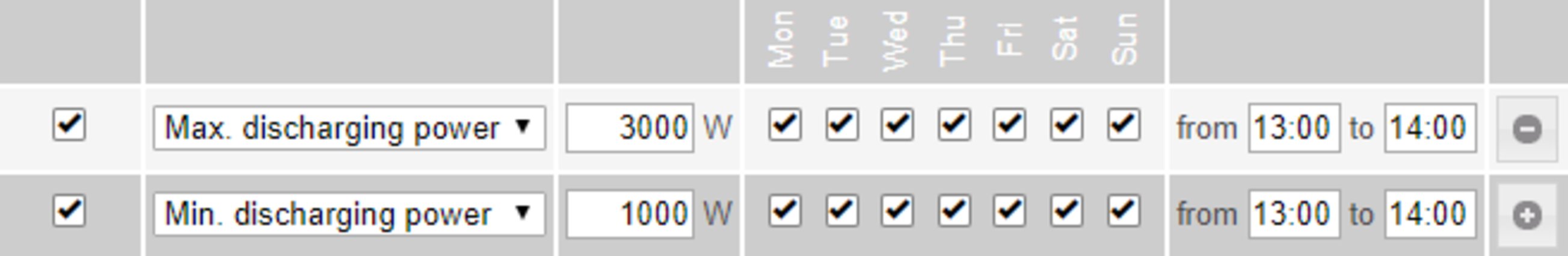 | ||||||||||||
|
|
|
|
|
|
|
|
|
|
|
| |
Specifying a defined charging power | ||||||||||||
Discharging limit |
| Discharge / charge |
|
| Charging limit | |||||||
|
|
|
|
|
|
|
|
|
|
|
| |
|
|
|
|
|
|
|
|
|
|
|
| |
|
|
|
|
|
|
|
|
|
|
|
| |
|
| Min. / max. charging 3000 W |
| |||||||||
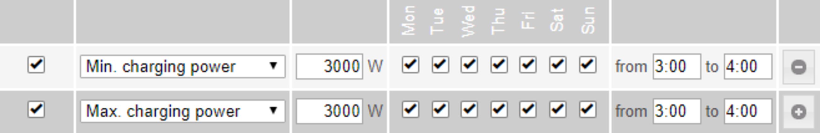 | ||||||||||||
|
|
|
|
|
|
|
|
|
|
|
|
|
Specifying a defined discharging power |
| |||||||||||
Discharging limit |
| Discharge / charge |
| Charging limit | ||||||||
|
|
|
|
|
|
|
|
|
|
|
| |
|
|
|
|
|
|
|
|
|
|
|
| |
|
|
|
|
|
|
|
|
|
|
|
| |
| Min. / max. discharging 3000 W |
|
|
|
| |||||||
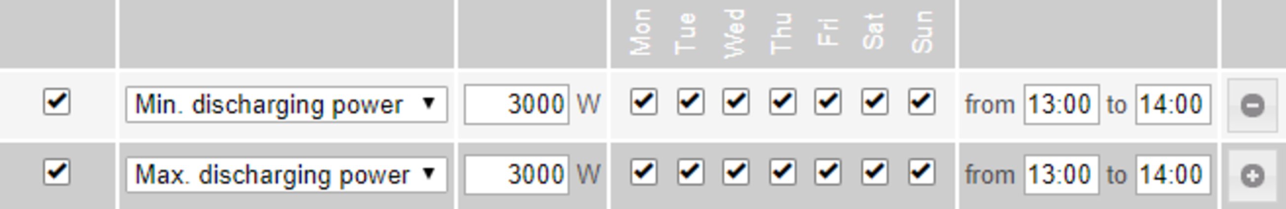 | ||||||||||||
Possible applications
The battery control parameters make the generated energy as optimally usable as possible. However, situations may arise in which PV energy cannot be fully used due to battery control parameters.
Example |
| |
Fronius Symo Hybrid 3.0-S: | 3000 W | (max. output power) |
Fronius Solar Battery 7.5 |
|
|
Defined discharge | 3000 W |
|
PV power | 1000 W |
|
In this case, the inverter would need to reduce the PV power to 0 W, as the output power of the Fronius Symo Hybrid 3.0-S is max. 3,000 W and the device is already fully utilised through the discharging.
Since it does not make sense to waste PV power, the power limitation for the battery control parameters is automatically adjusted so that no PV power is wasted. In the above example, this means that the battery is only discharged with 2,000 W, so that the 1,000 W of PV power can be used.
PV generator If there is no solar module connected to the Fronius hybrid inverter, the PV power option must be deactivated. The connected PV power must be entered in the field underneath. | |
Battery If a battery is connected to the Fronius hybrid inverter, it must be activated here. This setting can only be made when there is an active connection to a battery. If you are unable to make this setting, check whether the battery is switched on and whether the data connection has actually been established. If there is a connection, the current state of charge of the battery will be indicated underneath the battery symbol. | |
Enabling battery charging from DNO grid If you want the battery to be charged from the public grid, you can activate this here. Depending on what is required by standards or the feed-in tariff rules, it may be necessary to deactivate the setting. This setting does not affect the charging of the battery by other producers within the home. It merely relates to the process of drawing charging energy from the public grid. Regardless of this setting, the battery will still be charged from the public grid if needed for service reasons (e.g. to protect against deep discharge) | |
Fronius Checkbox 500V installed If a battery from the LG Chem ResuH series is connected, a Fronius Checkbox 500V must be installed and this option must be activated. | |
Emergency power Emergency power mode can be activated or deactivated here. The emergency power functionality can only be activated once the required IO assignments have been configured for emergency power. The meter must be installed at the feed-in point and configured. | |
External producer If further decentralised producers are installed in the household and have been integrated into the self-consumption rule for the Fronius hybrid inverter, you must activate this setting. This means that energy can be drawn from the household network and fed into the battery via the Fronius hybrid inverter. You can restrict how much power is consumed by the Fronius hybrid inverter by specifying a maximum AC power value (AC max.). The maximum power consumption is limited to the AC nominal output of the Fronius hybrid inverter. | |
Meter To ensure smooth operation in conjunction with other energy producers and in emergency power mode, it is important to install the Fronius Smart Meter at the feed-in point. The Fronius hybrid inverter and other producers must be connected to the public grid via the Fronius Smart Meter. This setting also affects how the Fronius hybrid inverter behaves overnight. If the function is deactivated, the inverter switches to Standby mode as soon as there is no more PV power available, provided that no energy management command is sent to the battery (e.g. minimum state of charge reached). The message "Power low" is displayed. The inverter restarts as soon as an energy management command is sent or there is sufficient PV power available. If the function is activated, the inverter remains permanently connected to the grid so that energy can be drawn from other producers at any time. Once the meter is connected, its position must be configured in the Fronius Datamanager. Several Fronius Smart Meters can be installed in the system. A different address needs to be set for each Smart Meter. The Watt value on the generator meter is the sum of all generator meters. The Watt value on the consumption meter is the value of all consumption meters. |
WICHTIG! Einstellungen im Menüpunkt Zähler dürfen nur von geschultem Fachpersonal durchgeführt werden!
Für den Menüpunkt Zähler ist die Eingabe des Service-Passwortes erforderlich.
Dreiphasige oder einphasige Fronius Smart Meter können verwendet werden. Die Auswahl erfolgt in beiden Fällen über den Punkt Fronius Smart Meter. Der Fronius Datamanager ermittelt automatisch den Zählertyp.
Es kann ein Primärzähler und optional mehrere Sekundärzähler ausgewählt werden. Der Primärzähler muss zuerst konfiguriert werden, bevor ein Sekundärzähler ausgewählt werden kann.
Wenn der Fronius Smart Meter als Zähler ausgewählt wird, muss über das Feld Einstellungen die Zählerposition eingestellt werden.
Zählerposition am Einspeisepunkt (1a)
Die eingespeiste Leistung und Energie werden gemessen. Anhand dieser Werte und der Anlagendaten wird der Verbrauch bestimmt.
Zählerposition im Verbrauchszweig (1b)
Die verbrauchte Leistung und Energie werden direkt gemessen. Anhand dieser Werte und der Anlagendaten werden die eingespeiste Leistung und Energie bestimmt.

Sekundärzähler
Wenn als Sekundärzähler ein Fronius Smart Meter ausgewählt wurde, öffnet sich ein Fenster zum Eingeben der Bezeichnung (frei wählbar) und ein Modbus-Adresse Feld. Im Modbus-Adresse Feld wird automatisch ein Wert vorgeschlagen (nächste freie Adresse im Adressbereich). Die Modbus-Adresse darf nicht doppelt vergeben werden. Nach der Eingabe auf das Feld Scan klicken.
Fronius Smart Meter 63A |
 |
Fronius Smart Meter 50kA-3 | |
 |
Im Menüpunkt EVU-Editor werden für ein Energieversorgungs-Unternehmen relevante Einstellungen vorgenommen.
Eingestellt werden können eine Wirkleistungs-Begrenzung in % und/oder eine Leistungsfaktor-Begrenzung.
WICHTIG! Einstellungen im Menüpunkt EVU-Editor dürfen nur von geschultem Fachpersonal durchgeführt werden!
Für den Menüpunkt EVU-Editor ist die Eingabe des Service-Passwortes erforderlich.
Cloud Control
Ein virtuelles Kraftwerk ist ein Zusammenschaltung mehrerer Erzeuger zu einem Verbund. Dieser Verbund kann über die Cloud-Steuerung per Internet gesteuert werden. Eine aktive Internetverbindung des Wechselrichters ist Voraussetzung dafür. Es werden Daten der Anlage übermittelt.
Wenn die Funktion Cloud-Steuerung für Anforderungen des Netzbetreibers/Energieversorgers zulassen aktiviert ist (service-Zugang erforderlich), ist die Funktion Cloud-Steuerung für virtuelle Kraftwerke zulassen automatisch aktiviert und kann nicht deaktiviert werden.
Die Funktion Cloud-Steuerung für Anforderungen des Netzbetreibers/Energieversorgers zulassen kann für den ordnungsgemäßen Betrieb der Anlage verpflichtend sein.
Eingangsmuster (Belegung der einzelnen I/Os):
Durch Klicken auf die Kontakte verändert sich das ausgewählte Eingangsmuster.
Angezeigt wird die virtuelle IO Zuordnung gemäß Abschnitt „Einstellungen - IO Zuordnung“ (siehe Seite (→)).
Bei älteren Software-Versionen kann die Anzeige abweichen.
Leistungsfaktor cos phi
ind = induktiv
cap = kapazitiv
EVU Ausgang (Rückmeldungs-Ausgang)
Dieser Ausgang ist frei konfigurierbar und wird aktiviert, sobald die Regel gesetzt ist.(z. B. zum Betrieb einer Signaleinrichtung). Werksseitig ist dafür der Ausgang I/O 0 voreingestellt.
ausgeschlossene Wechselrichter
Hier die DATCOM- bzw. Fronius Solar Net- Nummern der Wechselrichter eingeben, die von der Regelung ausgeschlossen sein sollen. Mehrere Wechselrichter durch Beistriche trennen.
Löschen / Hinzufügen einer Regel
+ = eine neue Regel hinzufügen
- = die aktuell ausgewählte Regel löschen
Schaltfläche Importieren - klicken, um Regeln im Format *.fpc zu importieren
Die Funktion der Schaltfläche Importieren ist vom verwendeten Browser abhängig, z. B. unterstützen Mozilla Firefox und Google Chrome die Funktion.
Schaltfläche Exportieren - klicken, um die Regeln im Format *.fpc separat abzuspeichern
| (1) | Ripple control signal receiver with 3 relays, for effective power limiting |
| (2) | Ripple control signal receiver with 3 relays, for power factor limiting |
| (3) | Fronius system monitoring I/Os |
| (4) | Consumers (e.g. signal lamp, signal relay) |

The ripple control signal receiver and the Fronius system monitoring connector are connected to one another by means of a four-pin cable in accordance with the connection diagram.
If the distance between the Fronius system monitoring datalogger and the ripple control signal receiver exceeds 10 m, a shielded cable is recommended.
DNO Editor settings:
Approved | Input pattern | Effective power | Power factor cos φ; | DNO output | Excluded inverter |
|
|---|---|---|---|---|---|---|
 | ||||||
 | ... not usable |  | ... not considered |  | etc. contact open |  | etc. contact closed |
A value for the apparent power consumption and apparent power output can be entered here for the Australia country setup.
Electricity retailers or grid operators may stipulate feed-in limitations for an inverter (e.g. max. 70% of kWp or max. 5 kW).
Dynamic power reduction takes account of self-consumption by the household before the power of an inverter is reduced:
With the Fronius Symo Hybrid, any PV power that is not allowed to be fed into the grid is used to charge the battery instead so that it does not go to waste. Dynamic power reduction is only activated if the battery is full or cannot be charged for some other reason.
"No limit" - The photovoltaic system converts all the available PV energy and feeds it into the grid.
"Limit for entire system" - The entire photovoltaic system is limited in accordance with a set power limit.
Field for entering the total DC system power in Wp.
This value serves as a reference for the rule and also for failures (e.g. a meter failure).
Field for entering the max. power in W or % (up to two decimal places, negative values can also be entered).
If no meter has been selected under the "Meter" menu item:
Max. power produced by the entire system.
If "Fronius Smart Meter" or S0 inverter has been selected under the "Meter" menu item: Max. grid power feed
Example: Dynamic power reduction | ||
PV system to Fronius Symo Hybrid: | 5000 W |
|
Household consumption: | 1000 W |
|
Max. grid power feed: | 60% = 3000 W |
|
|
|
|
Case 1: The battery may be charged |
|
|
Power at grid feed-in point: | 0 W |
|
Power at inverter output: | 1000 W |
|
Power to the battery: | 3000 W |
|
|
|
|
Case 2: The battery must not be charged | ||
Power at grid feed-in point | 3000 W |
|
Power at inverter output: | 4000 W |
|
Power to the battery: | 0 W |
|
|
|
|
In this example, no more than 3000 W may be fed into the grid at the grid feed-in point. However, any loads that are located between the inverter and the grid feed-in point can be supplied by additional power from the inverter. These loads are also compensated as required. | ||
For setting the control priorities for the ripple control signal receiver, the dynamic power reduction and control via Modbus
1 = highest priority, 3 = lowest priority
If you want the battery to be charged from the public grid, you can activate this here. Depending on what is required by standards or the feed-in tariff rules, it may be necessary to deactivate the setting.
This setting does not affect the charging of the battery by other producers within the home. It merely relates to the process of drawing charging energy from the public grid.
Regardless of this setting, the battery will still be charged from the public grid if needed for service reasons (e.g. to protect against deep discharge)
Example 1 | ||
 |
| PAC nom (inverter 1) £ PAC nom (hybrid) Example: 4.5 kW < 5 kW A Smart Meter is only required for the hybrid inverter. This must be installed at the feed-in point.
Hybrid system overview (web page): Settings – System overview: Meter must be configured at the feed-in point Settings – PSC editor: |
Example 2 If there are two Smart Meters in the feed-in branch, the Datamanager and the Fronius Datamanager (hybrid) in Solar.web cannot be shown combined in one PV system. Two individual PV systems must be created. | ||
 |
| PAC nom (inverter 1) > PAC nom (hybrid) Example: 7 kW > 5 kW Two Smart Meters are required for the inverters. These must be installed at the feed-in point.
Hybrid system overview (web page): Settings – System overview: Meter must be configured at the feed-in point
Datamanager overview (web page): Settings – System overview: Meter must be configured at the feed-in point Settings – PSC editor: |
Service: Battery module replacement (only with Fronius Solar Battery)
Service mode allows you to replace and extend the battery modules and is also intended for test purposes.
When this mode is activated, the Fronius Solar Battery is charged or discharged by means of a 10 A current or with the maximum inverter power, regardless of any other parameter settings. The charging or discharging process continues until the state of charge stands at 53% (the SOC of new battery modules on delivery). The process can be aborted at any time.
Once this SOC has been reached, the system maintains it until Service mode is deactivated again.
Disable calibration charging (only with Fronius Solar Battery)
Pressing "Disable" disables the calibration charging for three hours.
The inverter performs a system self-diagnosis that automatically detects many faults that may occur and shows them on the display. This means you are promptly made aware of malfunctions in the inverter or the photovoltaic system, or of any installation or operating faults.
If the system self-diagnosis has detected a specific fault, the associated status code will be shown on the display.
IMPORTANT! Status codes may sometimes appear briefly as a result of the inverter's control response. If the inverter then continues working with no sign of any problem, this means that there was no fault.
Class 1 status codes generally only arise momentarily and are caused by the public grid.
Example: The grid frequency is too high and the inverter may not feed any energy into the grid owing to a standard. There is nothing wrong with the device.
The initial response of the inverter is to disconnect itself from the grid. The grid is subsequently checked during the stipulated monitoring period. If no further problem has been detected by the end of this period, then the inverter will resume feeding energy into the grid.
The GPIS SoftStart function is activated according to the country setup:
After cutting out due to an AC error, the output power of the inverter is continuously increased in line with the national guidelines.
Code |
| Description |
| Behaviour |
| Remedy |
|---|---|---|---|---|---|---|
102 |
| AC voltage too high |
| Following careful testing and when the grid conditions are within the permissible range again, the inverter will resume feeding energy into the grid. |
| Check grid connections; |
103 |
| AC voltage too low |
|
| ||
105 |
| AC frequency too high |
|
| ||
106 |
| AC frequency too low |
|
| ||
107 |
| No AC grid |
|
| ||
108 |
| Stand-alone operation detected |
|
| ||
112 |
| RCMU error |
| |||
143 |
| Emergency power overload |
| Emergency power mode is interrupted. The inverter attempts to start emergency power mode three times; if this is unsuccessful status code 145 is displayed | Check emergency power circuit; if this status code keeps recurring, contact your system fitter | |
144 |
| Emergency power short-circuit |
| |||
145 |
| Status code 143 or 144 has occurred more than three times |
|
Class 3 includes status codes that may occur while feeding energy into the grid, but generally do not cause the process to be interrupted for any length of time.
The inverter disconnects automatically from the grid, the grid is then monitored as specified and the inverter attempts to resume feeding energy into the grid.
Code |
| Description |
| Behaviour |
| Remedy |
|---|---|---|---|---|---|---|
301 |
| Overcurrent (AC) |
| Short-term interruption while feeding energy into the grid. |
| *) |
302 |
| Overcurrent (DC) or battery not detected |
|
| ||
303 |
| DC module overtemperature (PV) |
| Short-term interruption while feeding energy into the grid. |
| Purge cooling air openings and heat sink; **) |
304 |
| AC module overtemperature |
|
| ||
305 |
| No power being fed in, despite closed relays |
| Short-term interruption while feeding energy into the grid. |
| **) |
306 |
| There is not enough PV power available for feeding energy into the grid and no power has been requested from the battery. |
| Short-term interruption while feeding energy into the grid. |
| Wait for sufficient insolation; wait for an energy management command; |
307 |
| DC low |
| Short-term interruption while feeding energy into the grid. |
| Wait for sufficient insolation; |
IMPORTANT! Due to the low level of insolation early in the morning and in the evening, the status codes 306 (Power low) and 307 (DC low) are displayed routinely at these times of day. These status codes do not indicate any kind of fault. | ||||||
308 |
| Intermediate circuit voltage too high | Short-term interruption while feeding energy into the grid. |
| **) | |
309 |
| PV input voltage too high | ||||
313 |
| Battery input voltage too high. | Short-term interruption while feeding energy into the grid. | Switch on, connect or check battery; | ||
314, |
| Internal system error |
| Short-term interruption while feeding energy into the grid. |
| *)
|
318 |
| Solar module return current detected |
| |||
324 |
| DC module overtemperature (battery) |
| Short-term interruption while feeding energy into the grid. |
| Purge cooling air openings and heat sink; **) |
*) If the status code is displayed all the time: Notify a Fronius-trained service technician. |
**) Fault is rectified automatically. If this status code keeps recurring, contact your system fitter |
Some of the class 4 status codes necessitate intervention by a Fronius-trained service engineer.
Code |
| Description |
| Behaviour |
| Remedy |
|---|---|---|---|---|---|---|
401 |
| Unable to communicate with the power stage set |
| The inverter will automatically attempt to connect again and, if possible, will resume feeding energy into the grid. |
| *) |
406 |
| DC module temperature sensor faulty (PV) |
|
| ||
407 |
| AC module temperature sensor faulty |
|
| ||
408 |
| DC component measured in the grid too high |
|
| ||
412 |
| Fixed voltage mode has been selected instead of MPP voltage mode, and the fixed voltage has been set to too low or too high a value. |
| - |
| **) |
415 |
| Safety cut-out via option card or RECERBO has triggered |
| The inverter is not feeding any energy into the grid. |
| *) |
416 |
| No communication possible between power stage set and control system. |
| The inverter will automatically attempt to connect again and, if possible, will resume feeding energy into the grid. |
| *) |
417 |
| Hardware ID problem |
| The inverter will automatically attempt to connect again and, if possible, will resume feeding energy into the grid. |
| Update inverter firmware; *) |
420 |
| Unable to communicate with system monitoring | ||||
425 |
| Unable to communicate with the power stage set | ||||
426 - 427 |
| Possible hardware fault | ||||
431, |
| Software problem |
| The inverter is not feeding any energy into the grid. |
| Perform AC reset (switch automatic circuit breaker off and on again); update inverter firmware; *) |
436 |
| Functional incompatibility (one or more PC boards in the inverter are not compatible with each other, e.g. after a PC board has been replaced) |
| The inverter will automatically attempt to connect again and, if possible, will resume feeding energy into the grid. |
| Update inverter firmware; *) |
437 |
| Power stage set problem | ||||
438 |
| Functional incompatibility (one or more PC boards in the inverter are not compatible with each other, e.g. after a PC board has been replaced) |
| The inverter will automatically attempt to connect again and, if possible, will resume feeding energy into the grid. |
| Update inverter firmware; *) |
445 |
|
|
| The inverter is not feeding any energy into the grid. |
| Update inverter firmware; *) |
447 |
| Insulation fault (PV or battery) |
| The inverter is not feeding any energy into the grid. |
| *) |
450 |
| Guard cannot be found | ||||
451 |
| Memory error detected |
| The inverter will automatically attempt to connect again and, if possible, will resume feeding energy into the grid. |
| *) |
452 |
| Communication error between the processors | ||||
453 |
| Grid voltage and power stage set are incompatible | ||||
454 |
| Grid frequency and power stage set are incompatible | ||||
456 |
| Anti-islanding function is no longer being implemented correctly | ||||
457 |
| Grid relay is sticking or the neutral conductor ground voltage is too high | The inverter is not feeding any energy into the grid. | Check the grounding (the neutral conductor ground voltage must be less than 30 V); *) | ||
458 | Error when recording measuring signal |
| The inverter is not feeding any energy into the grid. |
| *) | |
459 |
| Error when recording the measuring signal for the insulation test | ||||
460 |
| Reference voltage source for the digital signal processor (DSP) is working out of tolerance | ||||
461 | DSP data memory error | |||||
462 |
| Error during DC feed monitoring routine | ||||
463 |
| Reversed AC polarity, AC connector inserted incorrectly | ||||
474 |
| RCMU sensor faulty | The inverter is not feeding any energy into the grid. | **) | ||
475 |
| Insulation fault (connection between solar module and ground) | ||||
476 |
| Driver supply voltage too low | ||||
480, |
| Functional incompatibility (one or more PC boards in the inverter are not compatible with each other, e.g. after a PC board has been replaced) |
| The inverter is not feeding any energy into the grid. |
| Update inverter firmware; *) |
482 |
| Setup interrupted after initial start-up |
| The inverter is not feeding any energy into the grid. |
| Perform AC reset (switch automatic circuit breaker off and on again); update inverter firmware; *) |
484 - 489 |
| CAN transmit buffer is full |
| The inverter is not feeding any energy into the grid. |
| Perform AC reset (switch automatic circuit breaker off and on again); update inverter firmware; *) |
*) If the status code is displayed all the time: Notify a Fronius-trained service engineer.
**) If this status code keeps recurring, contact your system engineer.
Class 5 status codes do not generally interfere with feeding energy into the grid, but can cause restrictions. These status codes are displayed until they are acknowledged by pressing a key (however, the inverter continues to operate normally in the background).
Code |
| Description |
| Behaviour |
| Remedy |
|---|---|---|---|---|---|---|
502 |
| Insulation fault on solar modules or on the battery |
| Warning message is shown on the display |
| **) |
509 |
| No energy fed into the grid in the past 24 hours |
| Warning message is shown on the display |
| Acknowledge status code; |
515 |
| Unable to communicate with filter |
| Warning message on the display |
| *) |
516 |
| Unable to communicate with the data storage unit |
| Data storage unit warning message |
| *) |
517 |
| Power derating caused by excessively high temperatures |
| When power derating occurs, a warning message is shown on the display. |
| If necessary, purge cooling air openings and heat sink; |
519 |
| Unable to communicate with the data storage unit |
| Data storage unit warning message |
| *) |
520 |
| No energy fed into the grid by the PV in the past 24 hours |
| Warning message is shown on the display |
| Acknowledge status code; |
522 |
| DC low (PV). No PV voltage available. |
| Warning message on the display |
| In the case of hybrid systems, this message appears overnight if no photovoltaics are connected to the Fronius Symo Hybrid or in standby mode; *) |
558, |
| Functional incompatibility (one or more PC boards in the inverter are not compatible with each other, e.g. after a PC board has been replaced) |
| Warning message on the display | Update inverter firmware; *) | |
560 |
| Power derating caused by overfrequency |
| Displayed when grid frequency becomes excessively high. The power is reduced. |
| As soon as the grid frequency is back within the permissible range and the inverter has returned to normal operation, the fault is rectified automatically; **) |
567 |
| Power derating caused by overvoltage |
| Displayed when grid voltage becomes excessively high. The power is reduced. |
| As soon as the grid voltage is back within the permissible range and the inverter has returned to normal operation, the fault is rectified automatically; **) |
573 |
| Power derating caused by excessively low temperatures |
| When power derating occurs, a warning message is shown on the display. |
| Fault rectified automatically; **) |
*) If the status code is displayed all the time: notify a Fronius-trained service engineer
**) If this status code keeps recurring, contact your system engineer.
Some of the class 6 status codes necessitate intervention by a Fronius-trained service engineer.
Code |
| Description |
| Behaviour |
| Remedy |
|---|---|---|---|---|---|---|
601 |
| CAN bus is full |
| The inverter is not feeding any energy into the grid. |
| Update inverter firmware; *) |
603 |
| DC module temperature sensor faulty |
| The inverter will automatically attempt to connect again and, if possible, will resume feeding energy into the grid. |
| *) |
608 |
| Functional incompatibility (one or more PC boards in the inverter are not compatible with each other, e.g. after a PC board has been replaced) |
| The inverter is not feeding any energy into the grid. |
| Update inverter firmware; *) |
*) If the status code is displayed all the time: Notify a Fronius-trained service engineer.
**) Fault is rectified automatically. If this status code keeps recurring, contact your system engineer.
Class 7 status codes relate to the control system, the configuration and inverter data recording, and may directly or indirectly affect the process of feeding energy into the grid.
Code |
| Description |
| Behaviour |
| Remedy |
|---|---|---|---|---|---|---|
701 - 715 |
| Provides information about the internal processor status |
| Warning message on the display |
| *) |
721 |
| EEPROM has been re-initialised |
| Warning message on the display |
| Acknowledge status code; *) |
722 - 730 |
| Provides information about the internal processor status |
| Warning message on the display |
| *) |
746 |
| Error occurred during update process |
| Warning message on the display, update process is interrupted |
| Wait for 2 minutes, then start the update again; *) |
751 |
| Time lost |
| Warning message on the display |
| Reset time and date on the inverter; *) |
752 |
| Real Time Clock module communication error |
| |||
753 |
| Internal error: Real Time Clock module is in emergency mode |
| Time may be inaccurate or lost (feeding energy into the grid normal) |
| Reset time and date on the inverter |
754 - 755 |
| Provides information about the internal processor status |
| Warning message on the display |
| *) |
757 |
| Hardware error in the Real Time Clock module |
| Error message on the display; the inverter is not feeding any energy into the grid |
| *) |
758 |
| Internal error: Real Time Clock module is in emergency mode |
| Time may be inaccurate or lost (feeding energy into the grid normal) |
| Reset time and date on the inverter |
760 |
| Internal hardware error |
| Error message on the display |
| *) |
761 - 765 |
| Provides information about the internal processor status |
| Warning message on the display |
| *) |
766 |
| Emergency power limitation has been activated (max. 750 W) |
| Error message on the display | ||
767 |
| Provides information about the internal processor status |
| Warning message on the display |
| *) |
768 |
| Different power limitation in the hardware modules | ||||
772 |
| Data storage unit not available | ||||
773 |
| Software update group 0 (invalid country setup) | ||||
775 |
| PMC power stage set not available |
| Warning message on the display |
| Press “Enter” key to acknowledge error; *) |
776 |
| Invalid device type | ||||
781 - 794 |
| Provides information about the internal processor status |
| Warning message on the display |
| *) |
*) If the status code is displayed all the time: Notify a Fronius-trained service engineer.
Class 9 status codes only affect the Fronius Solar Battery. These are only displayed on the system monitoring page and are not shown on the inverter display.
Code |
| Description |
| Behaviour |
| Remedy |
|---|---|---|---|---|---|---|
975 |
| Software on device is inconsistent |
| The inverter is not feeding any energy into the grid |
| Update inverter firmware; *) |
976 |
| Unregistered battery module detected |
| Battery operation not possible, feed-in resumes |
| Enter activation key for battery module; *) |
977 |
| Incorrect number of battery modules connected to Fronius Solar Battery |
| Too many modules detected: Battery operation not possible | ||
978 |
| Communication error between Fronius Symo Hybrid and Fronius Solar Battery |
| Battery operation not possible, feed-in resumes |
| Check wiring; **) |
979 |
| Communication error between Fronius Symo Hybrid and Fronius Solar Battery |
| Battery operation not possible, feed-in resumes |
| Displayed in standby mode, if not in standby mode - check wiring; **) |
980 |
| No communication between Fronius Symo Hybrid and Fronius Solar Battery |
| Battery operation not possible, feed-in resumes |
| Switch on Fronius Solar Battery; check wiring; **) |
981 |
| Software version of Fronius Solar Battery is inconsistent |
| Battery operation not possible, feed-in resumes |
| *) |
983 |
| Communication error between battery controller and battery modules |
| Battery operation not possible, feed-in resumes |
| Check wiring in Fronius Solar Battery; check numbers of individual battery modules; check termination plug |
984 |
| Battery controller has stopped Charge mode |
| Battery operation not possible, feed-in resumes |
| Check error message on Fronius Solar Battery display; *) |
985 |
| Undervoltage at Fronius Solar Battery |
| Fronius Solar Battery has tripped due to undervoltage. Battery operation not possible, feed-in resumes |
| *) |
986 |
| Overtemperature at Fronius Solar Battery |
| Fronius Solar Battery has tripped due to overtemperature. Battery operation not possible, feed-in resumes |
| Reduce ambient temperature; switch off Fronius Solar Battery and activate it again after waiting an appropriate amount of time; *) |
987 |
| Undertemperature at Fronius Solar Battery |
| Fronius Solar Battery has tripped due to undertemperature. Battery operation not possible, feed-in resumes |
| Increase ambient temperature; switch off Fronius Solar Battery and activate it again after waiting an appropriate amount of time; *) |
988 |
| Communication error between Fronius Symo Hybrid and Fronius Smart Meter |
| No meter data available |
| Check wiring; **) |
989 |
| No communication between Fronius Symo Hybrid and Fronius Smart Meter |
| No meter data available |
| Check wiring; check Fronius Smart Meter power supply; **) |
*) If the status code is displayed all the time: Notify a Fronius-trained service technician
**) If this status code keeps recurring, contact your system engineer
1000 - 1299- Provide information on the status of the internal processor program | |
Description | Is of no concern when the inverter is working properly and only appears in the "Status PS" setup parameter. In the event of an actual error, this status code assists Fronius Technical Support during the error analysis. |
When operating the inverter in extremely dusty environments:
when necessary, clean the cooling elements and fan on the back of the inverter as well as the air intakes at the mounting bracket using clean compressed air.
The storage system performs a system self-diagnosis that automatically detects many faults that may occur. These are indicated on the display or via LEDs. This means you are promptly made aware of malfunctions in the storage system, or of any installation or operating faults.
If the system self-diagnosis has detected a specific fault, the associated status code will be shown on the display.
Indicator | Details | Solution |
NO MODULE | No module | Connect modules |
If modules are connected | The message on the left appears even if modules are connected. Check whether they have been connected properly. | |
OV Error | Overvoltage | Discharge |
DISCHARGE ERR | Deep discharge | Charge |
COMM ERR or CON= -------------ooox | Error affecting communication with connected modules. The example on the left illustrates a scenario in which one module (no. 00) is affected by a communication error, 3 modules (nos. 01, 02 and 03) are connected and the other addresses are without a connection. |
|
COMM OFF MODE | For maintenance only |
|
No information displayed | Wiring error, storage module addressing error or system-critical error | Check wiring, check address settings for individual storage modules |
If the data converter detects an error, the “State” LED lights up steady red to signal that an error has occurred. At the same time, the associated error messages are displayed via the “Error No” LEDs in accordance with table below. There are two different error categories:
Serious errors (1 - 5): In this case, the data converter has to be switched off and then back on again. If the error recurs, the data converter must be replaced and sent away for repair.
Warnings (6 - 15): These warnings are displayed for information only. They appear for 1 minute and are then reset automatically. If these warnings occur quite frequently, Customer Services should be notified accordingly.
These displays are not applicable in Configuration mode and are intended for internal purposes only.
LED8 | LED4 | LED2 | LED1 | Error no. or ID | Display |
0 | 0 | 0 | 0 | 0 | Reserved |
0 | 0 | 0 | 1 | 1 | Hardware fault |
0 | 0 | 1 | 0 | 2 | EEROM fault |
0 | 0 | 1 | 1 | 3 | Internal memory error |
0 | 1 | 0 | 0 | 4 | Fieldbus hardware fault |
0 | 1 | 0 | 1 | 5 | Script error |
0 | 1 | 1 | 0 | 6 | Reserved |
0 | 1 | 1 | 1 | 7 | RS transmission buffer overflow |
1 | 0 | 0 | 0 | 8 | RS receiver buffer overflow |
1 | 0 | 0 | 1 | 9 | RS timeout |
1 | 0 | 1 | 0 | 10 | General fieldbus error |
1 | 0 | 1 | 1 | 11 | Parity error or stop bit error (frame check) |
1 | 1 | 0 | 0 | 12 | Reserved |
1 | 1 | 0 | 1 | 13 | Fieldbus configuration error |
1 | 1 | 1 | 0 | 14 | Fieldbus data buffer overflow |
1 | 1 | 1 | 1 | 15 | Reserved |
Battery switches off during start-up procedure:
Keep the battery switched off for at least 120 minutes and then switch it on again. If this does not resolve the error, notify Customer Services.
Battery switched off with a SOC (state of charge) of 0%:
Communication error – Disconnect the inverter on the DC side and isolate it from the grid on the AC side. Wait 5 minutes and then reconnect the inverter on both the DC and AC sides. If this does not resolve the error, notify Customer Services.
Battery active, state of charge (SOC) is more than 90% and red LED is flashing:
Battery charging error – Disconnect the inverter on the DC side and isolate it from the grid on the AC side. Wait 30 minutes and then reconnect the inverter on both the DC and AC sides. If this does not resolve the error, notify Customer Services.
Battery not charging or discharging (SOC indicated on web interface does not match that of the battery):
Check whether battery is switched on – If it is not, switch it on.
If it is, there is a communication error – Disconnect the inverter on the DC side and isolate it from the grid on the AC side. Wait 5 minutes and then reconnect the inverter on both the DC and AC sides. If this does not resolve the error, notify Customer Services.
Battery no longer being displayed on web interface (triangular view instead of square view):
Check whether battery is switched on – If it is not, switch it on.
If it is, there is a communication error – Disconnect the inverter on the DC side and isolate it from the grid on the AC side. Wait 5 minutes and then reconnect the inverter on both the DC and AC sides. If this does not resolve the error, notify Customer Services.
Whenever an error message of any kind appears on the battery display:
Disconnect the inverter on the DC side and isolate it from the grid on the AC side. Wait 5 minutes and then reconnect the inverter on both the DC and AC sides. If this does not resolve the error, notify Customer Services.
Unusual increase in temperature or strange smells:
Switch off the system (battery main switch, DC side of inverter), ventilate the room and inform Customer Services.
Fronius Symo Hybrid | 3.0-3-S | 4.0-3-S | 5.0-3-S |
|---|---|---|---|
Input data |
|
|
|
PV input power | 5 kW | 6.5 kW | 8 kW |
MPP voltage range | 190 - 800 V DC | 250 - 800 V DC | 315 - 800 V DC |
Max. input voltage | 1000 V DC | ||
Start-up input voltage for feed-in | 200 V | ||
Nominal input voltage | 595 V | ||
Min. input voltage | 150 V DC | ||
Max. input current | 1 x 16.0 A | ||
Max. short circuit current of PV modules (ISC PV) | 24.0 A | ||
Number of MPP trackers | 1 | ||
Number of DC connections | 2 | ||
Battery input |
|
|
|
Max. output power to battery | Depending on the connected battery | ||
Max. input power from battery | Depending on the connected battery | ||
Output data |
|
| |
Nominal output power (Pnom) | 3000 W | 4000 W | 5000 W |
Max. output power | 3000 W | 4000 W | 5000 W |
Rated apparent power | 3000 VA | 4000 VA | 5000 VA |
Nominal grid voltage | 3~ EN 400/230 V3~ EN 380/220 V (+20% / -30%) | ||
Max. output current | 8.3 A | 8.3 A | 8.3 A |
Frequency (frequency range) | 50 Hz / 60 Hz (45 - 65 Hz) | ||
Total harmonic distortion | < 3 % | ||
Power factor (cos phi) | 0.85 - 1 ind./cap.2) | ||
Current (inrush) 6) | 38 A / 2 ms | ||
Max. output overcurrent protection | 25 A | ||
General data |
|
| |
Max. efficiency (PV - grid) | 97.5 % | 97.6 | |
Max. efficiency (PV - battery - grid) | > 90 % | > 90 % | > 90 % |
European efficiency (PV - grid) | 95.2 % | 95.7 % | 96 % |
Cooling | Controlled forced-air ventilation | ||
Protection class | IP 65 | ||
Dimensions h x w x d | 645 x 431 x 204 mm | ||
Weight | 22 kg | ||
Permitted ambient temperature | -25 °C - +60 °C | ||
Permissible humidity | 0 - 100 % | ||
EMC emission class | B | ||
DC / AC overvoltage category | 3/2 | ||
Pollution degree | 2 | ||
Noise emission | 59.5 dB(A) ref. 1pW | ||
Protection devices | |||
DC isolation measurement | Integrated | ||
DC overload performance | Operating point shift, power limiter | ||
DC disconnector | Integrated | ||
RCMU | Integrated | ||
Fronius Solar Battery | Battery 4.5 | Battery 6.0 | Battery 7.5 |
|---|---|---|---|
Electrical parameters |
|
|
|
Usable capacity | 3.6 kWh | 4.8 kWh | 6 kWh |
Cycle stability | 8000 | ||
Voltage range | 120 - 170 V | 160 - 230 V | 200 - 290 V |
Nominal charging power | 2400 W | 3200 W | 4000 W |
Nominal discharge power | 2400 W | 3200 W | 4000 W |
Max. charging current (limited by inverter) | 16.0 A | ||
Max. discharge current (limited by inverter) | 16.0 A | ||
Recommended fuse rating | Fuse 20 A / 1 kV / fast | ||
General data |
|
| |
Battery technology | LiFePO4 | ||
Dimensions h x w x d | 955 x 570 x 611 mm | ||
Weight | 91 kg | 108 kg | 125 kg |
Degree of protection | IP 20 | ||
Protection class | 1 | ||
Permissible ambient temperature | 5 °C - 35 °C | ||
Permissible storage temperature | -40 °C - 65 °C | ||
Permitted humidity | 0% - 95% (non-condensing) | ||
Interfaces | |||
Connection to inverter | Modbus RTU (RS485) | ||
|
|
|
|
Fronius Solar Battery | Battery 9.0 | Battery 10.5 | Battery 12.0 |
|---|---|---|---|
Electrical parameters |
|
|
|
Usable capacity | 7.2 kWh | 8.4 kWh | 9.6 kWh |
Cycle stability | 8000 | ||
Voltage range | 240 - 345 V | 280 - 400 V | 320 - 460 V |
Nominal charging power | 4800 W | 5600 W | 6400 W |
Nominal discharge power | 4800 W | 5600 W | 6400 W |
Max. charging current (limited by inverter) | 16.0 A | ||
Max. discharge current (limited by inverter) | 16.0 A | ||
Recommended fuse rating | Fuse 20 A / 1 kV / fast | ||
General data |
|
| |
Battery technology | LiFePO4 | ||
Dimensions h x w x d | 955 x 570 x 611 mm | ||
Weight | 142 kg | 159 kg | 176 kg |
Degree of protection | IP 20 | ||
Protection class | 1 | ||
Permissible ambient temperature | 5 °C - 35 °C | ||
Permissible storage temperature | -40 °C - 65 °C | ||
Permitted humidity | 0 - 95% | ||
Interfaces | |||
Connection to inverter | Modbus RTU (RS485) | ||
Supply voltage | 12 V DC |
Energy consumption | < 2 W |
Dimensions | 132 x 103 x 22 mm |
Ethernet (LAN) | RJ45, 100 Mbit |
WLAN | IEEE 802.11b/g/n client |
Ambient temperature | -20 - +65 °C |
I/O connection specifications |
|
Voltage level of digital inputs | Low = min. 0 V - max. 1.8 V |
Input current values of digital inputs | Dependent on input voltage; |
Switching capacity of digital outputs when supplied by Datamanager plug-in card | 3.2 W |
12.8 V | |
Max. switchable inductive loads at digital outputs | 76 mJ |
Modbus RTU | RS485 2 wire |
Factory settings for RS485 interface: |
|
|
|
| 1) | The values stated are defaults; the inverter is configured specifically to suit the requirements of the relevant country. |
| 2) | Depending on the country setup or device-specific settings (ind. = inductive; cap. = capacitive) |
| 3) | PCC = interface to the public grid |
| 4) | Maximum current from a defective PV module to all other PV modules. From the inverter itself to the PV side of the inverter it is 0 A |
| 5) | Guaranteed by the electrical configuration of the inverter |
| 6) | Current peak when switching on the inverter |
Fronius hybrid inverter:
CE mark
The devices conform to all the requisite and relevant standards and guidelines that form part of the relevant EU directive, and are therefore permitted to display the CE mark.
Emergency power operation
This version of the hybrid inverter is only intended for use in grid connected photovoltaic systems. A device update is required from the manufacturer in order to generate power independently of the public grid. As well as providing functional enhancements for the hardware and software, this update also includes relevant user documentation.
The hybrid inverter is delivered ready for supplying emergency power.
Power outage
The standard measurement and safety procedures integrated into the inverter ensure that in the event of a power outage, the feed-in of energy is immediately interrupted (e.g. switch-off by the energy supplier or damage to lines).
Detailed, country-specific warranty conditions are available at www.fronius.com/solar/warranty.
To obtain the full warranty period for your newly installed Fronius product, please register at www.solarweb.com.
Detailed, country-specific warranty conditions are available at www.fronius.com/solar/warranty.
To obtain the full warranty period for your newly installed Fronius product, please register at www.solarweb.com.
Waste electrical and electronic equipment must be collected separately and recycled in an environmentally responsible manner in accordance with the EU Directive and national law. Used equipment must be returned to the distributor or through a local, authorised collection and disposal system. Correct disposal of the used device promotes sustainable recycling of resources and prevents negative effects on health and the environment.
Packaging materials