- User informationTPS/i Interface Signal Descriptions
- General
- Digital Inputs
- Welding start (Welding on) - Single Bit
- Robot ready (Robot ready) - Single Bit
- Working mode - Single Bit
- Gas on (Gas on) - Single Bit
- Wire forward (Wire forwards) - Single Bit
- Wire backward (Wire return) - Single Bit
- Error reset (Reset error)
- Touch sensing (TouchSensing) - Single Bit
- Torch blow out (Blow out welding torch) - Single Bit
- Processline select (Process line selection) - Group Input
- Welding simulation (Welding simulation) - Single Bit
- Synchropulse on (SynchroPulse on) - Single Bit
- TAC on - Single Bit
- Cap-shaping - Single Bit
- Pilot arc on - Single Bit
- Booster manual - Single Bit
- ColdWire disable - Single Bit
- WireBrake on (Wire brake on) - Single Bit
- Torchbody Xchange (Change torch body) - Single Bit
- Teach mode - Single Bit
- WireSense start - Single Bit
- WireSense break - Single Bit
- TWIN mode (TWIN operating mode) - Group Input
- Documentation mode (Documentation mode) - Single Bit
- Disable process control (Deactivate process-dependent correction) - Group Input
- ExtInput 1-8 (External input 1-8) - Single Bit
- Job number (Job number) - Group Input
- Processline select (Process line selection) - Group Input
- Contact tip short circuit detection on (contact tip short circuit detection on) - Single Bit
- Analog Inputs
- Welding characteristic (Characteristic number) - Group Input
- Wire feed speed command value - Group Input / Analog Input
- Main- / Hotwire current command value - Analog Input
- Arclength correction (arc length correction) - Group Input / Analog Input
- Hotwire current (Hot-wire amperage) - Group Input / Analog Input
- Pulse-/ dynamic correction (Pulse/dynamic correction) - Group Input / Analog Input
- Wire correction (DynamicWire)
- Wire retract correction (Wire retraction correction) - Group Input / Analog Input
- Wire retract end - Analog Input
- Welding speed (Welding speed) - Group Input / Analog Input
- Wire positioning start - Analog Input
- Plasma gas command value - Analog Input
- Wire forward / backward length (length specification wire threading / wire retraction) - Group Input / Analog Input
- WireSense edge detection - Group Input / Analog Input
- Seam number (Seam number) - Group Input / Analog Input
- Digital Outputs
- Definition
- Heartbeat power source (Heartbeat power source) - Single Bit
- Power source ready (Welding machine ready) - Single Bit
- Warning (Warning) - Single Bit
- Process active (Process active) - Single Bit
- Current flow (current flow) - Single Bit
- Arc stable /Touch signal (Arc stable/touch signal) - Single Bit
- Main current signal (main current signal) - Single Bit
- Touch signal (Touch signal) - Single Bit
- Collisionbox active (CrashBox active) - Single Bit
- Robot motion release (Robot motion release) - Single Bit
- Wire stick workpiece (Wire stick workpiece) - Single Bit
- Electrode overloaded
- Short circuit contact tip (contact tip short circuit) - Single Bit
- Parameter selection internally (Internal parameter selection) - Single Bit
- Characteristic number valid (Characteristic number valid) - Single Bit
- Torchbody gripped (Torch body gripped) - Single Bit
- Command value out of range (set value out of range) - Single Bit
- Correction out of range (Correction out of range) - Single Bit
- Limitsignal (Limit signal) - Single Bit
- Standby active - Single Bit
- Main supply status (Mains voltage status) - Single Bit
- Sensor Status 1 (sensor status 1) - Single Bit
- Sensor Status 2 (sensor status 2) - Single Bit
- Sensor Status 3 (sensor status 3) - Single Bit
- Sensor Status 4 (sensor status 4) - Single Bit
- Function status - Single Bit
- Safety status - Single Bit
- Notification (Notification) - Single Bit
- System not ready - Single Bit
- Pulse current active
- Pilot arc active
- Process run
- Process Bit (Process bit) - Group Output
- Active process line - Single Bit
- Touch signal gas nozzle - Single Bit
- Twin synchronization active - Single Bit
- ExtOutput 1-8 (External output 1-8) - Single Bit
- Analog Outputs
- Welding voltage (Welding voltage) - Group Output / Analog Output
- Welding current (Welding current) - Group Output / Analog Output
- Wire feed speed (Wire speed) - Group Output / Analog Output
- Actual real value for seam tracking (Current actual value for seam tracking) - Group Output / Analog Output
- Error number (Error number) - Group Output / Analog Output
- Warning number (Warning number) - Group Output / Analog Output
- Motor current M1 (Motor current M1) - Group Output / Analog Output
- Motor current M2 (Motor current M2) - Group Output / Analog Output
- Motor current M3 (Motor current M3) - Group Output / Analog Output
- Actual real value AVC - Group Output / Analog Output
- Resistance - Single Bit
- Wire position (wire position) - Group Output / Analog Output
- Available Process Images
- Information on the use of the MIG/MAG standard manual, TIG, electrode, and ConstantWire welding processes
- Arc Break Monitoring
- Fronius Data Channel
- Signal sequence when selected using "Job Mode" operating mode
- Signal sequence when selected using "Characteristics Mode" operating mode
- WireSense - more information
- Process description for WireSenseContour sensing
- Process description WireSense edge detection (edge detection)
- Signal curve of Edge Detection Mode on a level surface
- Signal curve of Edge Detection Mode on a slanted surface
- Signal curve of Sensing Mode for different surface geometries
- Signal curve of WireSense break (during Sensing Mode)
- Representation of the possible WireSense-measurement range
- Note on ignition timeout (Ignition Timeout)
- Available signals for component scanning
- Limit Monitoring - functions and activation
- Limit Monitoring - details on the individual welding parameters
034-25092025
General
Data types used
UINT 16 (Unsigned Integer) = Whole number in the range from 0 to 65,535.
SINT 16 (Signed Integer) = Whole number in the range from -32,768 to 32,767.
Conversion examples:- For a positive value (SINT 16) = desired wirefeeder speed x factor = 12.3 m/min x 100 = 1230dec = 04CEhex.
- For a positive value (SINT 16) = desired arc length correction x factor = -6.4 x 10 = -64dec = FFC0hex.
Unsigned (UINT): | Signed (SINT): | ||||
|---|---|---|---|---|---|
Type: | Unsigned 16 Bit integer = 16 bits | Type: | Signed 16 Bit integer (15 bits + 1 Sign Bit*) | ||
Range: | 0 to 65,535 | Range: | -32,768 to 32,767 | ||
0000 | -10 | (0000000000000000) | 0000 | 0000 | (0*000000000000000) |
32,767 | 0 | (0111111111111111) | 56 | 56 | (0*000000000111000) |
65,535 | +10 | (1111111111111111) | -64 | -64 | (1*111111111000000) |
* = if the value entered has a negative sign, the sign is Bit High – see markings. | |||||
Behavior of the welding machine when an interface is connected
If a welding machine from the TPS/i series is connected to a robot interface, the settings on the welding machine remain unchanged (2-step mode, special 2-step mode, etc.).
If a welding machine from the TPS series is connected to a robot interface, the welding machine automatically selects 2-step mode.
Availability of Functions
As a result of updates, certain functions may be available on your device that are not described in this document, or vice versa.
Signal Transmission Time

Representation of the signal transmission time; the signals shown are for illustrative purposes only
WARNING!
Danger from incorrect operation and work that is not carried out properly.
This can result in serious personal injury and damage to property.
All the work and functions described in this document must only be carried out by technically trained and qualified personnel.
Read and understand this document in full.
Read and understand all safety rules and user documentation for this equipment and all system components.
Digital Inputs
Welding start (Welding on) - Single Bit
The rising edge of the Welding start signal starts the welding process.
- The welding process runs for as long as the Welding start signal is active.
Exceptions: The Robot ready signal is deactivated or the welding machine is reporting an error (for example: overtemperature, too little coolant, etc.). - The Welding start signal can be activated independently of the operating mode (internal parameter selection, special 2-step mode characteristics, Job Mode, etc.).
- Touch mode cannot be activated as long as the Welding start signal remains set.
- In single wire mode, the welding process is started on the active welding machine.
- In TWIN mode, the welding process is started on both welding machines.
Robot ready (Robot ready) - Single Bit
The robot sets this signal as soon as it is ready to weld.
- If the signal is reset by the robot during welding, the welding process is ended in a controlled manner (without any crater filling routines).
- In addition, the Robot not ready error is output. This error must either be reset on the welding machine control panel or using the robot interface.
- It is still possible to specify the set values in the internal parameter selection operating mode, even if the Robot ready signal is not set.
Working mode - Single Bit
This signal is used to select the operating mode of the welding machine.
Value range for operating mode: | |||||
|---|---|---|---|---|---|
Bit 4 | Bit 3 | Bit 2 | Bit 1 | Bit 0 | Description |
0 | 0 | 0 | 0 | 0 | Internal parameter selection |
0 | 0 | 0 | 0 | 1 | Special 2-step mode characteristics |
0 | 0 | 0 | 1 | 0 | Job Mode |
0 | 1 | 0 | 0 | 0 | 2-step mode characteristics |
0 | 1 | 0 | 0 | 1 | MIG/MAG standard manual, 2-step |
1 | 0 | 0 | 0 | 0 | Quiet mode |
1 | 0 | 0 | 0 | 1 | Stop coolant pump |
1 | 1 | 0 | 0 | 0 | R/L measurement |
- The control panel or a remote control can be used to specify all the set values and material settings important for welding. This makes creating and saving jobs easy.
- The robot outputs all other signals.
- These values can also be specified during welding.
- 4-step mode
- Special 4-step mode
- Electrode
- TIG
- To select welding parameters using the analog set values and the characteristic number (characteristic ID), the correct characteristic number must be used. The characteristic numbers can be found on the website of the welding machine, in the characteristics overview.
- The welding process is also defined using the characteristic number (MIG/MAG standard synergic, MIG/MAG pulse synergic, MIG/MAG LSC, MIG/MAG PMC, MIG/MAG CMT, TIG, TIG cold wire, TIG DynamicWire, HotWire).
- Only characteristics that have previously been approved for the welding machine can be selected.
- The parameters from the start of welding/end of welding are used in the special 2-step mode characteristics.

Special 2-step mode signal sequence
- The welding parameters are selected using the data saved in the jobs.
- The EasyJob function is deactivated as soon as a CC module (an RI IO/i or a RI IO PRO/i) is connected.
- There is no job with the number 0. Job number 0 can be used to select the job on the control panel of the welding machine.
- To select welding parameters using the analog set values and the characteristic number (characteristic ID), the correct characteristic number must be used. The characteristic numbers can be found on the website of the welding machine, in the characteristics overview.
- The welding process is also defined using the characteristic ID (MIG/MAG standard synergic, MIG/MAG pulse synergic, MIG/MAG LSC, MIG/MAG PMC, MIG/MAG CMT, etc.).
- Only characteristics that have previously been approved for the welding machine can be selected.

2-step mode signal sequence
For MIG/MAG standard manual characteristics, the 2-step mode characteristics must be used.
Description of MIG/MAG standard manual, 2-step:- MIG/MAG standard manual welding is a MIG/MAG welding process with no synergic function. Changing one parameter does not result in any automatic adjustments to the other parameters. All of the variable parameters (wire speed, welding voltage, arc-force dynamic) must therefore be adjusted individually, as dictated by the welding process in question.
- This signal is used to put the welding machine in Idle mode. In Idle mode, the booster is reduced to a minimum of the supply voltage in order to reduce the power consumption.
- In this working mode, it is not possible to start processes such as Welding start, Wire forward, Wire backward, TouchSensing, and Teach.
- In Working mode 17, the coolant pump is switched to "stop" (also possible from an external control). The cooling circuit is interrupted, all other functions of the welding machine remain active. The process parameter "Cooling unit operating mode" is not changed by Working mode 17.
- Once Working mode 17 has finished, the desired operating mode must be selected again.
- Welding is not possible in Working mode 17.
- In Working mode 24, the welding circuit resistance (R) and the welding circuit inductance (L) of the welding system are measured.
Requirements for R/L measurement:
The welding system must be complete: closed welding circuit with welding torch and torch hosepack, wirefeeders, return lead cables, and interconnecting hosepacks.
Performing an R/L measurement:- Use the robot or the controller to select Working mode 24. The current values for welding circuit inductance and welding circuit resistance are displayed.
- IMPORTANT! Contact between the earthing clamp and the workpiece must be made on a cleaned workpiece surface.
- The R/L measurement is started with the "Wire forward" input signal.
- After the measurement has been carried out, the new measured values for the welding circuit resistance (R) and the welding circuit inductance (L) are displayed on the R/L alignment wizard.
The "Function status" output signal transmits the status of the measurement (Inactive, Idle, Finished, Error).
The "Resistance" output signal transmits the measured value. - Select a different Working mode to exit the R/L alignment wizard.
Gas on (Gas on) - Single Bit
The Gas on signal opens the gas solenoid valve and thus activates the gas flow.
- As long as the signal is High, the gas solenoid valve remains open.
- The gas flow can be activated independently of the operating mode (internal parameter selection, special 2-step mode characteristics, Job Mode, etc.).
- During welding, the gas pre-flow and the gas post-flow are controlled by the welding machine. It is therefore not necessary to activate the gas pre-flow and gas post-flow separately.
- If the Gas on High signal is set before the Welding start signal, the gas pre-flow of the welding machine is not active.
- The Gas on signal can only be set if the Robot ready signal is set at the same time. If this is not the case, the gas flow must be activated by pressing a button on one of the Fronius system components (welding machine, wirefeeder, torch hosepack, etc.).
- In single wire mode with a Single-torch body, the gas solenoid valve of the active process line is opened.
- In TWIN mode, both gas solenoid valves are opened.
- When welding with a TWIN torch body, both gas solenoid valves are always opened.
Wire forward (Wire forwards) - Single Bit
The Wire forward signal activates the start of the wirefeeder.
- The wire electrode is threaded into the hosepack without current or gas.
- The wirefeeder can be activated independently of the operating mode (internal parameter selection, special 2-step mode characteristics, Job Mode, etc.).
- The signal corresponds to the wire threading button on the control panel of the welding machine, on the wirefeeder, and on the torch hosepack. The precise function of the wire threading button is described in the operating instructions of the respective system components/the documentation of the whole welding system.
- As long as the Wire forward signal is set, the Wire backward signal cannot be set.
- The Wire forward signal can only be set if the Robot ready signal is set at the same time. If this is not the case, wire threading must be controlled using the wire threading button on one of the Fronius system components (wirefeeder, torch hosepack, etc.).
- The wire electrode can be threaded a maximum of 50 m (164 feet 0.5 inches) (=safety stop).
- Pulse signal = wire electrode moves approx. 1 mm (0.039 inches) forwards.
- Continuous signal = creep function—the wirefeeder is stopped as soon as the wire electrode touches the welding material.
- In single wire mode, the wire electrode of the active process line is fed.
- In TWIN mode, both wire electrodes are fed.
- If the TWIN operating mode changes during wirefeeding, the wirefeeding is adapted in line with the change.
Wire backward (Wire return) - Single Bit
The Wire backward signal activates the retraction of the wire electrode.
- It can be used to retract the wire electrode out of the welding torch completely or only by a specific length.
- The retraction can be activated independently of the operating mode (internal parameter selection, special 2-step mode characteristics, Job Mode, etc.).
- The signal corresponds to the wire-return button on the control panel of the welding machine, on the wirefeeder, and on the torch hosepack. The precise function of the wire-return button is described in the operating instructions of the respective system components/the documentation of the whole welding system.
- As long as the Wire backward signal is set, the Wire forward signal cannot be set.
- The Wire backward signal can only be set if the Robot ready signal is set at the same time. If this is not the case, retraction of the wire electrode must be controlled using the wire-return button on one of the Fronius system components (wirefeeder, torch hosepack, etc.).
- The wire electrode can be retracted a maximum of 50 m (164 feet 0.5 inches) (=safety stop).
- Pulse signal = wire moves approx. 1 mm (0.039 inches) backwards.
- Continuous signal = permanent wire retraction.
- In single wire mode, the wire electrode of the active process line is fed.
- In TWIN mode, both wire electrodes are fed.
- If the TWIN operating mode changes during wirefeeding, the wirefeeding is adapted in line with the change.
Error reset (Reset error)
If an error message is output on the welding machine, the error is reset using the Error reset signal.
In order to reset the signal successfully, the signal must remain set for at least 10 ms.
WARNING!
Danger due to welding processes starting unexpectedly.
This can result in serious personal injury and damage to property.
The cause of the error must always be resolved before the error message is reset using the Error reset signal.
WARNING!
Danger due to welding processes starting unexpectedly if the Error reset signal is always active and the Welding start signal is set at the same time.
This can result in serious personal injury and damage to property.
Ensure that the Welding start signal is not set during troubleshooting if the Error reset signal is active at the same time.
Additional information for TWIN systems:
The signal resets the error on both welding machines.
Touch sensing (TouchSensing) - Single Bit
CAUTION!
Danger from unexpected electric shock.
When Touch sensing is activated, a voltage of approx. 70 V (up to 3 A) is applied to the wire electrode/gas nozzle.
If touched, a harmless but perceptible electric shock can be transmitted. An involuntary reaction to this shock can cause injuries.
Do not touch the wire electrode and the torch body (gas nozzle, contact tip, etc.) when Touch sensing is active.
When Teach mode is active, do not touch any electrically conductive parts that are touched by the wire electrode and the torch body (gas nozzle, contact tip, etc.).
The Touch sensing signal can be used to detect contact between the wire electrode or the gas nozzle and the workpiece = short circuit between workpiece and wire electrode or gas nozzle.
- If the Touch sensing signal is set, the control panel of the welding machine displays touch and a voltage of approx. 70 V (current limited to 3 A) is applied to the wire electrode/the gas nozzle.
- If a short circuit occurs, this is reported to the robot controller by the Arc stable signal / Touch signal (see page (→)) and Touch signal (see page (→)).
- The output of the Arc stable / Touch signals (see page (→)) and Touch signal (see page (→)) lasts 0.3 seconds longer than the duration of the short circuit current.
- As long as the Welding start signal is set, the Touch sensing signal cannot be activated.
- The welding process can also be started if the TouchSensing signal is active. This automatically deactivates the touch function.
- TouchSensing can be activated independently of the operating mode (internal parameter selection, special 2-step mode characteristics, Job Mode, etc.).
Touch sensing function/process:

NOTE!
Risk of signal overlap.
This can lead to problems in connection with the Wirebrake option.
After deactivating the Touch sensing signal, wait 4 seconds before setting another signal.
- Touch sensing is started on both welding machines, but is only ever carried out on one wire electrode.
- In single wire mode, the wire electrode of the active process line is used.
- In TWIN mode, the wire electrode of the leading process line (Lead) is used—only when the wire electrode of the Lead-welding machine is touched are the Touch Sensing signals generated.
Additional information for Touch sensing with the gas nozzle:
If the position detection is carried out by touching the workpiece with the gas nozzle (instead of the wire electrode), the gas nozzle must be connected to the welding current lead using an RC circuit or the Touch Sensing Adv. option.
Gas nozzle + RC element:- The use of an RC circuit is required so that if the gas nozzle comes into contact with the workpiece during welding:
- Unacceptable currents in the connection between the gas nozzle and the welding current lead are avoided.
- The welding process is not influenced.
- When the position is detected by contact with the gas nozzle, the short circuit current flows until the capacitors of the RC circuit are charged (a few milliseconds). To ensure safe position detection by the robot controller, the Arc stable and Touch sensing signals are on for 300 milliseconds longer than the short circuit current.
- With the OPT/i Touch Sense Adv. option, the TouchSensing signal is also used to check whether there is a short circuit between the gas nozzle and the contact tip.
Torch blow out (Blow out welding torch) - Single Bit
If the robot wirefeeder is fitted with an additional solenoid valve for compressed air, this is controlled using the Torch blow out signal.
The signal is used to remove contaminations from the gas nozzle during torch cleaning.
Processline select (Process line selection) - Group Input
This signal is used to select the desired process line.
The signal is only available if:- The OPT/i TPS Dual Head Robotics option is present in the welding machine.
- Each process line has its own wirefeeder.
Bit 1 | Bit 0 | Description |
|---|---|---|
0 | 0 | Wirefeeder 1 (factory setting) |
0 | 1 | Wirefeeder 2 |
1 | 0 | Wirefeeder 3 |
- It is only possible to switch between the process lines using the robot.
- The inactive wirefeeders are only supplied with voltage, the system bus is switched off. This has the following limitations:
- Available software updates will only be applied to the wirefeeder if the wirefeeder is part of the process line selected.
- The CAT signal of inactive wirefeeders is not evaluated.
- It is not possible to carry out gas tests, wire threading, wire retraction, etc. on the hosepacks of the inactive process lines.
- The welding torch identification of hosepacks of the inactive process lines is not read.
- The remote controls of the inactive process lines are also inactive.
Welding simulation (Welding simulation) - Single Bit
The welding machine uses the Welding simulation signal to simulate an actual welding process.
- This allows the user to follow a welding path that has been programmed in the robot controller without any actual welding taking place.
- All signals are set as if actual welding were taking place (no actual values)
- Process active
- Current flow
- Arc stable
- Robot motion release
- Main current signal
- No arc is ignited (Welding start signal).
- No wire electrode is moved (Wire forward and Wire backward signal).
- The gas solenoid valve is not triggered ( Gas on signal).
- The gas purging valve is not triggered ( Torch blow out signal).
Synchropulse on (SynchroPulse on) - Single Bit
The Synchropulse on signal activates/deactivates the SynchroPulse function set in the welding machine. The signal can be set before or during welding.
TAC on - Single Bit
The tacking function is used for the TIG DC welding process.
Whenever a period of time is set for the "Tacking" (4) parameter under process parameters/TIG DC settings, the tacking function is assigned to the 2-step and 4-step modes. The sequence of operating modes remains unchanged.
The tacking (TAC) indicator lights up on the status bar:

During this time, a pulsed welding current is available, which optimizes the merging of the weld pool when tacking two components.
How the tacking function works during TIG DC welding:

| Key: |
| I-P | Pulse current | |
I-S | Starting current |
| F-P | Pulse frequency *) | |
I-E | Final current |
| dcY | Duty cycle | |
tup | UpSlope |
| I-G | Base current | |
tDown | DownSlope |
| I-1 | Main current | |
*) (1/F-P = Time between two pulses) | |||||
NOTE!
When using a pulsed welding current:
The welding machine automatically controls the pulse parameters according to the set main current (I-P).
No pulse parameters need to be set.
- After the starting-current phase has elapsed (I-S)
- With the UpSlope phase tup
- After the DownSlope has elapsed (tDown)
- Before the final current phase (I-E)
The pulsed welding current lasts until the final current phase (I-E) (TIG DC tacking parameter "on").
Cap-shaping - Single Bit
Only for iWave AC/DC!
The "Cap-shaping" signal enables automatic cap-shaping when the AC welding process is selected.
This takes into account the set electrode diameter to deliver optimum results. Automatic cap-shaping ensures that the optimum cap is formed during the start of welding. After that, cap-shaping is automatically deactivated and welding must be restarted.
Setting range: off / on
Factory setting: off
off: Automatic cap-shaping function is deactivated.
on: The optimum cap for the entered diameter of the tungsten electrode is shaped during the start of welding.
The automatic cap-shaping function is then reset and deactivated.

(1) ... before ignition
(2) ... after ignition
(2) ... after ignition
Pilot arc on - Single Bit
The plasma pilot arc starts due to a rising edge of the "Pilot arc on" signal.
- The plasma pilot arc burns as long as the "Pilot arc on" signal is active.
Exceptions: The "Robot ready" signal is deactivated or the welding machine issues an error message (e.g., overtemperature, insufficient coolant, etc.). - The pilot arc remains active after the main arc has gone out as long as the "Pilot arc on" signal is set.
- The "Pilot arc on" signal can be activated independently of the operating mode (internal parameter selection, special 2-step mode characteristics, Job Mode, etc.).
- Touch mode and wire threading cannot be activated as long as the "Pilot arc on" signal is set.
Booster manual - Single Bit
This signal can be used to deactivate the automatic Idle mode.
If there is no welding activity for a certain period of time, the welding machine switches to Idle mode. In Idle mode, the booster is reduced to a minimum of the supply voltage in order to reduce the power consumption.
The booster will be re-initialized every time at the start of welding. This means there may be a short delay of a few milliseconds before the booster is active again.
Note: If this signal is activated, the idle power consumption can rise above 50 watts.
ColdWire disable - Single Bit
This signal interrupts the wirefeeder of the cold wire during the welding process without ending the welding process itself. If the cold wire is interrupted, the value set for "Wire retract end" is ALWAYS used.
WireBrake on (Wire brake on) - Single Bit
By activating the WireBrake on signal, the wire electrode is held by the OPT/i MHP WireBrake.
OPT/i MHP WireBrake is a mechanical component that is installed between the torch hosepack and the torch body.
WireBrake on can be activated independently of the operating mode (internal parameter selection, special 2-step mode characteristics, Job Mode, etc.).
If OPT/i MHP WireBrake is detected in the system, the WireBrake on signal is automatically set in Touch sensing.
NOTE!
Risk of signal overlap.
This may result in problems holding the wire electrode.
It is not recommended to activate any other signals while the WireBrake on signal is active.
After deactivating the WireBrake on signal, wait 4 seconds before activating another signal.
A detailed description of the program sequence can be found in the Robacta TX 10i/G/W Operating Instructions.
Additional information for TWIN systems:
WireBrake is not available for TWIN hosepacks.
Torchbody Xchange (Change torch body) - Single Bit
The Torchbody Xchange signal is only available in conjunction with a torch body change system.
If the signal is High, the torch body coupling is opened.
Torchbody Xchange can be activated independently of the operating mode (internal parameter selection, S2-step mode characteristics, Job Mode).
NOTE!
Risk of signal overlap.
This may result in problems changing the torch body.
It is not recommended to activate any other signals while the Torchbody Xchange signal is active.
After deactivating the Torchbody Xchange signal, wait 3 seconds before activating another signal.
Detailed description of the program sequence—see operating instructions for the torch body change system.
Teach mode - Single Bit
WARNING!
Danger from electrical current due to Teach mode being active. When Teach mode is active, a voltage of approx. 70 V (up to 3 A) is applied to the wire electrode/contact tip.
May result in serious injury or death.
Do not touch the wire electrode and the contact tip when Teach mode is active.
When Teach mode is active, do not touch any electrically conductive parts that are touched by the wire electrode or the contact tip.
Teach mode can be used to create the robot program. Teach mode being activated (signal High) avoids the wire electrode becoming bent when setting up the robot.
Teach mode can be activated independently of the operating mode (internal parameter selection, special 2-step mode characteristics, Job Mode, etc.).
Teach mode function:
 |
|
 |
|
 |
|
- As soon as the wire electrode touches the workpiece, the Touch signal is set to High.
- Only when the wire electrode is no longer in contact with the workpiece is the Touch signal set to Low.
NOTE!
Danger from using Teach mode in conjunction with very soft wire electrodes.
This may result in unexpected welding results caused by bent wire electrodes.
Using Teach mode with very soft wire electrodes may result in the wire electrodes becoming bent. To prevent wire burn-back caused by the bent wire electrode, unwind the wire electrode by approx. 50 mm (1.97 inch) before the start of welding and shorten it.
- In single wire mode, Teach mode is activated for the active process line.
- In TWIN mode, Teach mode is activated for both process lines
- The scanning frequency of the wire electrode at a component contact with the Lead-welding machine is higher than the scanning frequency with the Trail-welding machine.
WireSense start - Single Bit
WARNING!
Danger from electrical current. When the WireSense start signal is active, a voltage of approx. 50 V (up to 1 A) is applied to the wire electrode/contact tip.
May result in serious injury or death.
Do not touch the wire electrode and contact tip when the WireSense start signal is active.
Do not touch any electrically conductive parts that are touched by the wire electrode or the contact tip when the WireSense start signal is active.
- Function WireSense - Sensing Mode (= contour detection): Used for scanning the component surface / component geometry
- This function is active when the Signal WireSense start is activated and a height value less than 0.5 mm (0.02 inches) is specified for the WireSense edge detection signal.
- Edge detection (WireSense - Edge Detection Mode function) is not active with this function.
- The Touch signal is not output for this function.
- WireSense - Edge Detection Mode function (= edge detection): Used to detect a single edge
- This function is active when the Signal WireSense start is activated and a height value greater than / equal to 0.5 mm (0.02 inches) is specified for the WireSense edge detection signal.
- For more information, see WireSense edge detection - Group Input / Analog Input on page (→).
- As soon as the signal is active, the forward and backward movement of the wire electrode begins.
- After the wire electrode has touched the workpiece for the first time, the point of the first contact is used as a zero position (reference point) for the WireSense height measurement.
- If WireSense is already active (WireSense process already running), the wire electrode can be conveyed a maximum of 25 mm (0.98 inches). If there is no workpiece contact within 25 mm (0.98 inches), wirefeeding is stopped.
- If WireSense is started for the first time (without previous workpiece contact), the wire electrode can be conveyed a maximum of 450 mm (17.72 inches). If there is no workpiece contact within 450 mm (17.72 inches), wirefeeding is stopped.
For more information on WireSense, see section WireSense - more information from page (→).
Additional information for TWIN systems:- In single wire mode, WireSense is only activated and evaluated for the active process line.
- In TWIN mode, WireSense is activated for both process lines. Please note the following:
- The Touch signal, which can be output at the WireSense edge detection, is only triggered by the Lead-welding machine.
- The position signals during contour detection (WireSense - Sensing Mode) are output at the interface with two individual output signals simultaneously—with the Signal Wire position for welding machine 1 and welding machine 2.
WireSense break - Single Bit
- This signal only has an impact if the WireSense start signal is active at the same time.
- This signal is used to interrupt the WireSense process but at the same time to obtain the reference point that was determined when the WireSense process was first started.
- The WireSense break signal stops the wire movement while the WireSense start signal is active - for example, to bridge larger distances between two workpieces (if the wire electrode is touching a workpiece while the WireSense break signal is active, the wire electrode is still retracted to prevent bending).
- The reference point, which was determined when the WireSense process was first started, remains stored while the WireSense break signal is active.
- After the WireSense break signal is deactivated, the wire movement starts again and the height measurement continues.
- When the WireSense break signal is set, the Arc stable signal is disabled at the same time. As soon as the WireSense break signal is deactivated again, the Arc stable signal is reactivated.
For more information on WireSense, see section WireSense - more information from page (→).
Additional information for TWIN systems:- In single-wire operation, WireSense break nur die Drahtelektrode der aktiven Prozesslinie stops.
- In TWIN mode, WireSense break beide Drahtelektroden stops.
TWIN mode (TWIN operating mode) - Group Input
This signal defines which TWIN mode will be used to operate the respective welding machine.
The following can be specified using the signal:- Single wire / or TWIN welding.
- Which process line is leading during TWIN welding (Lead).
- Which process line is active during single wire welding.
The operating modes can be changed both before and during welding.
Bit 32 | Bit 33 | Description |
|---|---|---|
0 | 0 | Single wire mode, line 1 |
0 | 1 | TWIN mode, line 2 leading (Lead) |
1 | 0 | TWIN mode, line 1 leading (Lead) |
1 | 1 | Single wire mode, line 2 |
Documentation mode (Documentation mode) - Single Bit
The signal is used to select whether the weld seams are counted by the welding machine or the robot.
Signal level = Low:- The welds are counted by the welding machine.
- Each time welding is completed, the weld seam count increases by 1. Switching the welding machine off and on again restarts the count at 0. In addition, it is also possible to specify an initial value (starting the count at 10 instead of 0, for example).
- Exception: If the Fronius Data Channel is used, the number of weld seams is specified using the Fronius Data Channel and not the welding machine.
- The number of weld seams is specified using the robot.
Disable process control (Deactivate process-dependent correction) - Group Input
If this signal is active, a process-dependent correction (Process controlled correction signal) can be manually selected on the welding machine.
Additional information for TWIN systems:
Process-dependent corrections must be activated separately for both welding machines.
ExtInput 1-8 (External input 1-8) - Single Bit
Inputs used to control options, such as OPT/i RI FB REL.
- Max. voltage = DC 113 V / AC 68 V
- Max. current load 1 A
Example outputs: ExtInput1 = OPT_Output 1.
The inputs have no effect on other signals (for example Robot ready, etc.)

| (1) | Robot output |
| (2) | Welding machine input |
| (3) | Options output |
- TWIN systems are only compatible with the OPT/i RI FB REL EXT 8I/8O option.
- The signals are forwarded to both welding machines and are then available at the outputs of the relay station used.
Job number (Job number) - Group Input
This signal is used to carry out welding using the welding parameters that are saved under the selected job number (1-1000).
Job number 0 can be used to select the job on the control panel of the welding machine.
Additional information for TWIN systems:
Job numbers must be selected separately for both welding machines.
Processline select (Process line selection) - Group Input
This signal is used to select the desired process line.
The signal is only available if:- The OPT/i TPS Dual Head Robotics option is present in the welding machine.
- Each process line has its own wirefeeder.
Bit 1 | Bit 0 | Description |
|---|---|---|
0 | 0 | Wirefeeder 1 (factory setting) |
0 | 1 | Wirefeeder 2 |
1 | 0 | Wirefeeder 3 |
- It is only possible to switch between the process lines using the robot.
- The inactive wirefeeders are only supplied with voltage, the system bus is switched off. This has the following limitations:
- Available software updates will only be applied to the wirefeeder if the wirefeeder is part of the process line selected.
- The CAT signal of inactive wirefeeders is not evaluated.
- It is not possible to carry out gas tests, wire threading, wire retraction, etc. on the hosepacks of the inactive process lines.
- The welding torch identification of hosepacks of the inactive process lines is not read.
- The remote controls of the inactive process lines are also inactive.
Contact tip short circuit detection on (contact tip short circuit detection on) - Single Bit
- If a short circuit is detected, the signal Short circuit contact tip is set high.
This signal is only available for TWIN systems operating in TWIN mode (not available for single wire operation).
Analog Inputs
Welding characteristic (Characteristic number) - Group Input
This signal is used to specify the welding process using the characteristic number.
Characteristic number 0 can be used to select the material setting and the welding process on the control panel of the welding machine.
Examples of characteristic numbers:- 2765 = G3Si1 / 1.2 mm / Ar 15-20%, CO2 / LSC
- 3189 = G3Si1 / 1.2 mm / Ar 15-20%, CO2 / PMC
Additional information for TWIN systems:
Characteristic numbers must be selected separately for both welding machines.
Wire feed speed command value - Group Input / Analog Input
The signal is used to control the wire speed when using a cold wirefeeder.
As described below, the set value can be specified on a Digital Interface or an Analog Interface.
The following set value specifications apply to the MIG/MAG standard synergic, MIG/MAG pulse synergic, MIG/MAG PMC, MIG/MAG LSC, CMT, ConstantWire, TIG ColdWire.
Digital Interface: | ||
Value range | Designation | Min./max. possible value |
-32768 | Wire feed speed | -327.68 m/min (depending on wirefeeder) |
+32767 | Wire feed speed | +327.67 m/min (depending on wirefeeder) |
Additional information for TWIN systems: | ||
Analog Interface: | ||
Value range | Designation | Min./max. possible value |
0 V | Wire feed speed | 0% (depending on wirefeeder) |
10 V | Wire feed speed | 100% (depending on wirefeeder) |
Additional information for TWIN systems: | ||
- Factor = 100
- Data type SINT
- Specified as a percentage. Example: 15% = 1,500 step change.
Main- / Hotwire current command value - Analog Input
The main current/hot-wire amperage is set on the selected characteristic by entering a value between 0 and 6,553.5 (0-100%).
Digital Interface: | ||
Value range | Designation | Min./max. possible value |
0 | Main- / Hotwire current | 0 A |
6,553.5 | Main- / Hotwire current | 6,553.5 A |
Analog Interface: | ||
Value range | Designation | Min./max. possible value |
0 V | Hotwire current | 0 |
10 V | Hotwire current | 100% |
Arclength correction (arc length correction) - Group Input / Analog Input
As described below, the value for the arc length correction can be specified on a Digital Interface or an Analog Interface.
The following specifications apply to the MIG/MAG standard synergic, MIG/MAG pulse synergic, MIG/MAG PMC, and MIG/MAG LSC welding processes.
Digital Interface: | ||
Value range | Designation | Min./max. possible value |
-32,768 | Arc length correction | -10% = shorter arc |
0 | Arc length correction | 0% = saved value |
+32,767 | Arc length correction | +10% = longer arc |
Additional information for TWIN systems: | ||
Analog Interface: | ||
Value range | Designation | Min./max. possible value |
0 V | Arc length correction | -10% = shorter arc |
5 V | Arc length correction | 0% = saved value |
10 V | Arc length correction | +10% = longer arc |
Additional information for TWIN systems: | ||
- Factor = 10
- Data type SINT
- Specified as absolute value. Example: 1.5 = 150 step change.
Hotwire current (Hot-wire amperage) - Group Input / Analog Input
As described below, the value for the hot-wire amperage can be specified on a Digital Interface or an Analog Interface.
The following specifications apply to the ConstantWire welding process.
Digital Interface: | ||
Value range | Designation | Min./max. possible value |
0 | Hot-wire amperage | 0 |
65,535 | Hot-wire amperage | 6553.5 A |
Additional information for TWIN systems: | ||
Analog Interface: | ||
Value range | Designation | Min./max. possible value |
0 V | Hot-wire amperage | 0 |
10 V | Hot-wire amperage | 100% |
Additional information for TWIN systems: | ||
Pulse-/ dynamic correction (Pulse/dynamic correction) - Group Input / Analog Input
As described below, the value for the pulse/dynamic correction can be specified on a Digital Interface or an Analog Interface.
The following specifications apply to the MIG/MAG standard synergic, MIG/MAG pulse synergic, MIG/MAG PMC, and MIG/MAG LSC welding processes.
Digital Interface: | ||
Value range | Designation | Min./max. possible value |
-32,768 | Pulse/dynamic correction | -10% = pulse/dynamic correction |
0 | Pulse/dynamic correction | 0% = saved value |
+32,767 | Pulse/dynamic correction | +10% = pulse/dynamic correction |
Additional information for TWIN systems: | ||
Analog Interface: | ||
Value range | Designation | Min./max. possible value |
0 V | Pulse/dynamic correction | -10% = pulse/dynamic correction |
5 V | Pulse/dynamic correction | 0% = saved value |
10 V | Pulse/dynamic correction | +10% = pulse/dynamic correction |
Additional information for TWIN systems: | ||
Wire correction (DynamicWire)
The signal is used to fine-tune the wire speed with TIG DynamicWire.
Digital Interface: | ||
Value range | Designation | Min./max. possible value |
-32768 | Wire correction | -10 |
0 | Wire correction | 0 |
+32767 | Wire correction | +10 |
Setting range: -10 - // +10
Factory setting: 0
-10 = slow immersion
+10 = fast immersion
Wire retract correction (Wire retraction correction) - Group Input / Analog Input
As described below, the value for the wire retraction correction can be specified on a Digital Interface or an Analog Interface.
The following specifications apply to the MIG/MAG standard synergic, MIG/MAG pulse synergic, MIG/MAG PMC, MIG/MAG LSC, CMT, and ConstantWire welding processes.
Digital Interface: | ||
Value range | Designation | Min./max. possible value |
0 | Wire retraction correction | 0 |
65,535 | Wire retraction correction | +10 |
Additional information for TWIN systems: | ||
Analog Interface: | ||
Value range | Designation | Min./max. possible value |
0 V | Wire retraction correction | 0 |
10 V | Wire retraction correction | +10 |
Additional information for TWIN systems: | ||
Wire retract end - Analog Input
The signal indicates how far the welding wire is retracted after the end of welding or when the wire stops.
Digital Interface: | ||
Value range | Designation | Min./max. possible value |
0 | Wire retraction | OFF |
65,535 | Wire retraction | 50 mm |
Setting range: off / 1-50 mm
Factory setting: off
Welding speed (Welding speed) - Group Input / Analog Input
This value is used to transmit the robot's TCP speed.
Additional information for TWIN systems:
The TCP speed for both welding machines is transmitted at the same time.
Wire positioning start - Analog Input
The signal indicates the length of the welding wire and how far it is from the workpiece before welding starts.
Digital Interface: | ||
Value range | Designation | Min./max. possible value |
0 | Wire positioning start | OFF |
65,535 | Wire positioning start | 50 mm |
Setting range: off / 1-50 mm
Factory setting: off
Plasma gas command value - Analog Input
Digital Interface: | ||
Value range | Designation | Min./max. possible value |
0 | Plasma gas command value | 0.1 l/min |
65,535 | Plasma gas command value | 9.0 l/min |
Plasma gas flow set value:
0.1-9.0 l/min
Wire forward / backward length (length specification wire threading / wire retraction) - Group Input / Analog Input
- The signal is active as soon as a value greater than or equal to 1 mm (0.039 inches) is entered (0 = signal inactive).
- If a value greater than or equal to 1 mm (0.039 inches) is specified, the wire electrode is only fed by the specified value when the signal Wire forward is set. After reaching the preset value, the end of wirefeeding takes place automatically.
- As soon as the specified value is reached:
- The Touch signal (WORD 0 / Byte 0 / Bit 7) is set
- The signal Wire forward must be deactivated (otherwise the wire threading function remains active)
- The signal Wire position is accompanied by an output defining how far the wire electrode has been moved [the value remains set for 1 second; +/- 1 mm (+/- 0.039 inches)]
- If the wire electrode touches the workpiece before the preset value has been reached, the Touch signal (WORD 0 / Byte 0 / Bit 7) and additionally the Arc stable / Touch signal (WORD 0 / Byte 0 / Bit 5) are set. The end of wirefeeding takes place automatically.
- The wire electrode can be conveyed a maximum of 50 m (164 feet 0.5 inches) (=safety stop).
If not all wire feeds of the welding system are synchronized (e.g. due to the combination of a Robacta Drive drive unit and a Stand Alone unwind wirefeeder), inaccuracies of +/- 5 mm (+/- 0.196 inches) may occur in the specification of the wire electrode fed due to the system.
As described below, the set value can be specified on a Digital Interface or an Analog Interface.
The following set value specifications apply to the MIG/MAG standard synergic, MIG/MAG pulse synergic, MIG/MAG PMC, and MIG/MAG LSC welding processes.
Digital Interface: | |
Value range | Min./max. possible value |
-32,768 | 1 mm (0.039 inches) |
+32,767 | 10,000 mm (393.7 inches) |
Additional information for TWIN systems:
The digital set value must be entered separately for both welding machines.
Analog Interface: | |
Value range | Min./max. possible value |
0 V | 1 mm (0.039 inches) |
10 V | 10,000 mm (393.7 inches) |
Additional information for TWIN systems:
It is not possible to enter an analog set value on TWIN systems.
Signal course - set Wire forward length (= 25 mm / 0.984 inches) could be reached according to plan: |
| Signal course - workpiece contact occurs before the set Wire forward length (= 25 mm / 0.984 inches) could be reached: |
 |  |
WireSense edge detection - Group Input / Analog Input
- If a value less than 0.5 mm (0.02 inches) is specified with the WireSense edge detection signal, the WireSense start signal is used for contour detection.
- The surface of the component is scanned cyclically by the wire electrode and the measured height value is output continuously.
- The Touch signal is not active at the same time.
- If a value of 0.5-20 mm (0.02-0.787 inches) is specified with the WireSense edge detection signal, the WireSense start signal is used to detect and measure a single edge.
- The specified value (threshold value) defines the minimum edge height that can be detected by the welding machine.
- For example, if you use a 2 mm (0.079 inches) thick sheet that is welded with an overlap joint, it is recommended to use this signal to specify 1.5 mm (0.059 inches) (it is not recommended to always set the minimum value of 0.5 mm (0.02 inches), as this setting may cause false detection. For example, this may be caused by welding spatter, inaccurate robot movements, etc.).
- The Touch signal is output when an edge is detected.
Digital Interface: | ||
Value range | Designation | Min./max. possible value |
0 | Threshold | 0 mm (0 inches) |
200 | Threshold | 20 mm (0.787 inches) |
For more information on WireSense, see section WireSense - more information from page (→).
Additional information for edge detection:
A further 0.2 mm is subtracted from the specified threshold value for the internal welding machine calculation.
- In single wire mode, only the wire electrode of the active process line is used for WireSense edge detection .
- In TWIN mode, both wire electrodes are used for WireSense edge detection . The Touch signal is only ever generated and output by the Lead- welding machine.
- The two wire electrodes from the TWIN system can only be used for the same WireSense- function:
- Both wire electrodes for either contour detection or edge detection.
Seam number (Seam number) - Group Input / Analog Input
The seam number of the respective welding process is specified using this value, for example for documentation purposes.
For more detailed information regarding weld seam documentation, please refer to Documentation mode (Documentation mode) - Single Biton page (→).
Additional information for TWIN systems:
The seam number for both welding machines is specified at the same time.
Digital Outputs
Definition
Digital outputs are signals from the welding machine to the robot.

| (1) | Robot input |
| (2) | Welding machine output |
Definition
Digital outputs are signals from the welding machine to the robot.
| (1) | Robot input |
| (2) | Welding machine output |
Heartbeat power source (Heartbeat power source) - Single Bit
As soon as the interface creates an authenticated connection to the welding machine, this signal changes its activity with a frequency of 1 Hz (1 second High, 1 second Low, 1 second High, etc.).
Additional information for TWIN systems:
As soon as the RI FB/i TWIN Controller establishes an authenticated connection to both welding machines, this signal changes its activity with a frequency of 1 Hz (1 second High, 1 second Low, 1 second High, etc.).
Power source ready (Welding machine ready) - Single Bit
- The signal is High when the welding machine is ready to weld.
- The signal is Low, if a fault occurs on the welding machine (Error) or a notification (Notification) is issued.
- The signal can also be called a "common error", as it is set to Low for all types of internal and external error.
Additional information for TWIN systems:
The signal is only set to High when both welding machines are ready to weld.
Warning (Warning) - Single Bit
- The signal is High when the welding machine issues a warning.
- The signal remains High until the reason for the warning has been rectified.
- The signal automatically changes to Low, as soon as the reason for the warning has been eliminated.
- The signal has no effect on the welding process or the operability of the welding machine (welding can be started; running process is not interrupted, etc.).
Additional information for TWIN systems:
The signal is set to High as soon as one of the two welding machines issues a warning.
Process active (Process active) - Single Bit
The Process active signal is set from the beginning of gas pre-flow to the end of gas post-flow in order to inform the robot that welding is still taking place. This means that, for example, the dwell time of the robot can be synchronized at the end of the weld seam to ensure that there is an ideal gas shield.
If the Welding start signal is set, the gas pre-flow time begins to count down, even before the arc is ignited.
After extinguishing the arc, the gas post-flow time begins to count down.

| (1) | Process active (process active) |
Additional information for TWIN systems:
The signal is set as soon as one of the two welding machines becomes active.
Current flow (current flow) - Single Bit
This signal is set as soon as the wire electrode touches the workpiece and current begins to flow – the signal is High as soon as the workpiece is touched.
During welding the signal can fall to Low during all welding processes – the signal functions in the same way for all welding processes.

| (1) | Current flow (current flow) |
Additional information for TWIN systems:
The signal is set to High as soon as one of the two wire electrodes becomes live.
Arc stable /Touch signal (Arc stable/touch signal) - Single Bit
- This signal is set as soon as the wire electrode touches the workpiece and current flows, thus reporting to the robot controller that the arc is burning.
- If the Arc stable / Touch signal is active, the arc monitoring is also active. This is not the case for the Current flow signal.
- If an arc monitoring time has been set, the Arc stable / Touch signal is only reset if the Current flow signal is inactive for longer than the set arc monitoring time.
- The Arc stable / Touch signal is active as long as the arc is burning.
- The Arc stable / Touch signal is also set as soon as the wire electrode or the gas nozzle comes into contact with the workpiece in Touch mode (Touch sensing signal is active).
- For more information about the Touch sensing signal, see Touch sensing (TouchSensing) - Single Bit on page (→).
- When using WireSense, the signal Arc stable / Touch signal is set as soon as the wire electrode comes into contact with the workpiece for the first time and the WireSense process runs stable (For example, when the WireSense - Slaghammer function is automatically triggered, the Arc stable / Touch signal is only set after the WireSense - Slaghammer function has been successfully executed)
- For more information on WireSense, see section WireSense start - Single Bit from page (→).
- For more information on WireSense, see section WireSense start - Single Bit from page (→).
- When unwinding the wire electrode (Wire forward signal), the Arc stable / Touch signal is set as soon as the wire electrode touches the workpiece.
| (1) | Arc stable / Touch signal (arc stable/touch signal) |
The signal functions differently depending on the welding process. See below for an overview of the function of the signal in conjunction with the different welding processes.
MIG/MAG pulse synergic, MIG/MAG PMC, mixed processes:
Example of correct ignition at the start of welding.

MIG/MAG pulse synergic, MIG/MAG PMC, mixed processes:
Example of incorrect ignition at the start of welding.

MIG/MAG standard synergic, MIG/MAG standard manual, MIG/MAG LSC, MIG/MAG CMT, MIG/MAG CMT mixed processes:
Example of correct ignition at the start of welding.

MIG/MAG standard synergic, MIG/MAG standard manual, MIG/MAG LSC, MIG/MAG CMT, MIG/MAG CMT mixed processes:
Example of incorrect ignition at the start of welding.

- In single-wire operation, the following applies:
- Once welding is started, the Arc stable / Touch signal is set as soon as the wire electrode comes into contact with the workpiece and current begins to flow.
- In Touch mode, the Arc stable / Touch signal is set as soon as the wire electrode touches the workpiece.
- When using WireSense, the Arc stable / Touch signal is set as soon as the WireSense-process is running stably (as soon as the Slaghammer is ended).
- In TWIN operation, the following applies:
- Once welding is started, the Arc stable / Touch signal is set as soon as both wire electrodes come into contact with the workpiece and current begins to flow.
- In Touch mode the Arc stable / Touch signal is set as soon as the wire electrode of the lead welding machine or the gas nozzle touches the workpiece.
- When unwinding the wire electrode (Wire forward signal), the Arc stable / Touch signal is set as soon as one of the two wire electrodes touches the workpiece.
- When using WireSense, the Arc stable / Touch signal is set as soon as the WireSense-process is running stably with both wire electrodes (as soon as the Slaghammer is ended).
- In the case of operation with no earth connection, contact of the wire with the workpiece is not detected.
- The Arc stable / Touch signal is set automatically as soon as the gas pre-flow is finished.
- The Arc stable / Touch signal is automatically deactivated as soon as the Welding start signal is deactivated.
Main current signal (main current signal) - Single Bit
If welding is carried out with a defined starting current and a defined final current, the Main current signal is set between the end of the starting current and the start of the final current phases.

| (1) | Main current signal (main current signal) |
- In single wire mode, the signal is set as soon as the active process line starts welding using the main current.
- In TWIN mode, the signal is set as soon as both process lines start welding using the main current.
Touch signal (Touch signal) - Single Bit
- In Touch mode the gas nozzle or the wire electrode touches the workpiece (depending on the system configuration).
- In Teach mode the wire electrode touches the workpiece.
- During unwinding (Wire forward signal) the wire electrode touches the workpiece.
- When using the WireSense edge detection, function, the set threshold value has been reached and thus the required edge has been successfully detected.
- For more information on WireSense, see section WireSense - more information from page (→).
- In single-wire operation, the following applies:
- In Touch mode the touch signal is set as soon as the wire electrode or the gas nozzle of the active welding machine touches the workpiece.
- When unwinding the wire electrode (Wire forward signal), the Touch signal is set as soon as the wire electrode of the active welding machine touches the workpiece.
- When using the Teach mode, the touch signal is set as soon as the wire electrode of the active welding machine touches the workpiece.
- When using WireSense edge detection, the Touch signal is set as soon as an edge has been detected by the active welding machine.
- In TWIN operation, the following applies:
- In Touch mode the Touch signal is set as soon as the wire electrode of the Lead-welding machine or the gas nozzle touches the workpiece.
- When unwinding the wire electrode (Wire forward signal), the Touch signal is set as soon as the wire electrode of the Lead-welding machine touches the workpiece (the Trail-welding machine is ignored).
- When using the Teach mode, the Touch signal is set as soon as the wire electrode of the Lead-welding machine touches the workpiece (the Trail-welding machine is ignored).
- When using WireSense edge detection, the Touch signal is set as soon as an edge is detected by the Lead-welding machine (the Trail-welding machine is ignored).
Collisionbox active (CrashBox active) - Single Bit
If a collision occurs (with the workpiece, clamping device, etc.) while using the CrashBox, the contact of the CrashBox is opened and the Collisionbox active signal is set to Low.
In this case, it is recommended that:- Immediate shutdown of the robot is initiated.
- The welding process is ended.
The signal has no effect on the welding machine.
Robot motion release (Robot motion release) - Single Bit
The signal is active from the end of the starting current to the end of the gas post-flow.
The starting current time begins as soon as Current flow is High. Even if Current flow is interrupted, the starting current time continues to run until the set end (the starting current time does not reset).
If an arc monitoring time has been set, the Robot motion release signal is only reset if the Current flow signal is inactive for longer than the set arc monitoring time.

| (1) | Robot motion release (Robot motion release) |
- Arc stable High.
- Current flow High.
- The starting current time has elapsed (not the slope time).
- Arc stable Low.
- Welding start Low.
- The gas post-flow has ended.
Additional information for TWIN systems:
The signal is output separately for both process lines.
Wire stick workpiece (Wire stick workpiece) - Single Bit
The signal is High if a wire stick is detected on the workpiece. This signal is always output regardless of other settings.
Additional information for TWIN systems:
The signal is set to High as soon as one of the two wire electrodes sticks.
Electrode overloaded
If the tungsten electrode is overloaded, this can result in material detachment on the electrode, which can cause contamination to enter the weld pool.

If the tungsten electrode is overloaded, the "Electrode overloaded" indicator lights up on the status bar of the control panel and this signal is output.
The "Electrode overloaded" indicator depends on the set electrode diameter and the set welding current.
Short circuit contact tip (contact tip short circuit) - Single Bit
This signal is set to High if a short circuit between the contact tip and the gas nozzle has been detected in the following operating states:
- In Touch mode
- In welding operation
- During wire threading
- In Teach mode
- In WireSense mode
In addition, a separate warning message is output.
The cause of a short circuit between the contact tip and the gas nozzle can be pollution, for example due to welding spatter.
In order for this signal to be available, the TouchSense Adv. option must be installed in the welding system.
Additional information for TWIN systems:
This signal is set to High if a short circuit between the contact tip of the lead welding machine and the gas nozzle has been detected in the aforementioned operating states.
In addition, this signal is set to High when the input signal Contact tip short circuit detection on is set to High and a short circuit between the two contact tips is detected.
Once again here, the cause of a short circuit between the contact tips may be pollution, for example due to welding spatter.
The OPT/i TouchSense Adv. option does not have to be available in the welding system for performing the short-circuit check between the two contact tips.
Parameter selection internally (Internal parameter selection) - Single Bit
This signal indicates whether the parameter selection has been set to "internal".
This setting can be applied:- Using the Working mode signal/internal parameter selection, or
- directly on the welding machine itself under: Defaults / Interface setup / Welding parameters.
- Welding process (MIG/MAG pulse synergic, MIG/MAG standard synergic, etc.)
- Operating mode (2-step mode, etc.)
- Characteristic/job number (depending on the welding process)
- Wirefeeder
- Arc length correction
- Pulse/dynamic correction
- Wire retraction
- Process-dependent correction
- SynchroPulse on/off
Additional information for TWIN systems:
The signal is set to High as soon as parameter selection is set to "internal" on one of the two process lines.
Characteristic number valid (Characteristic number valid) - Single Bit
If the signal is High, the selected characteristic and the selected process are approved and can be used.
Torchbody gripped (Torch body gripped) - Single Bit
This signal indicates that a Fronius torch body has been registered in the system.
Command value out of range (set value out of range) - Single Bit
This signal indicates that the „Wire feed speed command value“ input is outside of the possible range.
The signal is High if, for example:- The possible range is limited by the wirefeeder:
- Selected wirefeeder set value = 25 m/min (984.25 inches/min)
- Maximum wirefeeder set value based on characteristic = 25 m/min (984.25 inches/min)
- Maximum possible speed of the wirefeeder = 15 m/min (590.55 inches/min).
- The possible range is limited by the characteristic:
- Selected wirefeeder set value = 25 m/min (984.25 inches/min)
- Maximum wirefeeder set value based on characteristic = 15 m/min
- Maximum possible speed of the wirefeeder = 30 m/min (1181.1 inches/min).
Additional information for TWIN systems:
The signal is set as soon as one of the two process lines exceeds a defined range.
Correction out of range (Correction out of range) - Single Bit
This signal indicates that at least one of the selected corrections (for example, Arc length correction) is outside of the specified range.
Additional information for TWIN systems:
The signal is set as soon as one of the selected corrections exceeds the defined range.
Limitsignal (Limit signal) - Single Bit
This signal indicates that the set limits for voltage, current, wirefeeder, welding time, and energy input have been exceeded or not reached.
This signal is only available in Job Mode.
Requirements- In the menu on the welding machine "Process parameters/Job/Optimize Job/Limit monitoring/Limit reaction", the reaction is set to "Warning" or "Error".
- OPT/i Limit Monitoring enabled for the welding machine.
Additional information for TWIN systems:
The signal is output separately for both process lines.
- Limit Monitoring - functions and activation from page (→) and
- Limit Monitoring - details on the individual welding parameters from page (→).
Standby active - Single Bit
This signal indicates that the welding machine is in Working mode 16 or has automatically switched to Idle mode.
Main supply status (Mains voltage status) - Single Bit
This signal indicates whether a phase error has occurred on the welding machine (incorrect power supply to the welding machine).
If this error has occurred, the error numbers 6451 or 6515 will be shown on the display of the welding machine or transmitted to the robot via the interface as an Error number signal.
Additional information for TWIN systems:
The signal is set to High as soon as a phase error occurs on one of the two welding machines.
Sensor Status 1 (sensor status 1) - Single Bit
This signal indicates the status of the wire end option 4,100,869.
Signal level | Description |
|---|---|
High | Wire electrode present |
Low | No wire electrode present |
The signal is output as soon as the sensor of the option is detected in the system.
If there is no sensor in the system, the signal is set to High.
Additional information for TWIN systems:
The signal is output separately for both process lines.
Sensor Status 2 (sensor status 2) - Single Bit
This signal indicates the status of the wire end option 4,100,879.
Signal level | Description |
|---|---|
High | Wire electrode present |
Low | No wire electrode present |
The signal is output as soon as the sensor of the option is detected in the system.
If there is no sensor in the system, the signal is set to High.
Additional information for TWIN systems:
The signal is output separately for both process lines.
Sensor Status 3 (sensor status 3) - Single Bit
This signal indicates the status of the wire end option 4,100,878.
Signal level | Description |
|---|---|
High | Wire electrode present |
Low | No wire electrode present |
The signal is output as soon as the sensor of the option is detected in the system.
If there is no sensor in the system, the signal is set to High.
Additional information for TWIN systems:
The signal is output separately for both process lines.
Sensor Status 4 (sensor status 4) - Single Bit
The signal indicates the status of the wire buffer set CMT TPS/i 4,001,763 option.
Signal level | Description |
|---|---|
High | Wire buffer is not empty |
Low | Wire buffer is empty |
The signal is output as soon as the sensor of the option is detected in the system.
If there is no sensor in the system, the signal is set to High.
Additional information for TWIN systems:
The signal is output separately for both process lines.
Function status - Single Bit
This signal indicates the status of the R/L-measurement, which is transmitted during the measurement in Working mode 24 (R/L-measurement).
Bit 1 | Bit 0 | Description |
|---|---|---|
0 | 0 | Inactive |
0 | 1 | Idle |
1 | 0 | Finished |
1 | 1 | Error |
Safety status - Single Bit
This signal indicates the status of the OPT/i Safety Stop PL d and OPT/i TPS External Stop options.
Bit 1 | Bit 0 | Description |
|---|---|---|
0 | 0 | Reserve |
0 | 1 | Hold |
1 | 0 | Stop |
1 | 1 | Not installed/active |
Notification (Notification) - Single Bit
- The signal is High when the welding machine issues a notification.
- Notifications can arise, for example, due to set process limits, external sensors, etc.
- The signal automatically interrupts the welding process.
- Operation of the welding machine is possible while the signal is High.
- The signal remains High until the reason for the notification has been resolved.
- The signal automatically changes to Low, as soon as the reason for the notification has been eliminated.
Additional information for TWIN systems:
The signal is set to High as soon as one of the two welding machines issues a notification.
System not ready - Single Bit
- This signal is Low if there are no error messages in the welding system (all error sources must be eliminated for the signal to change to Low.
- This signal is High as soon as a component of the welding system outputs an error message.
- A component of the welding system performs an update.
- Occurrence of an emergency stop.
- In conjunction with wire sensors (ring sensor, sensor on wire drum, etc.), for example, errors 16828, 16837, 16838.
- The Robot ready signal is Low.
- During the welding process, a welding torch detection problem occurs (BID error).
Pulse current active
This output signal on the interface indicates the "Pulse high phase" and works up to a maximum pulse frequency of 10 Hz.
This ensures that the robot reliably receives all signals up to a frequency of 10 Hz. At frequencies above 10 Hz, correct transmission of the "Pulse high" signal can no longer be guaranteed.
A permanent high signal is output at a pulse frequency above 10 Hz. For example, the pulse duration at a frequency of 1 kHz is only 1 ms.
Pilot arc active
This signal indicates when the plasma pilot arc is active.
The Process active signal is set from the beginning of gas pre-flow to the end of gas post-flow in order to inform the robot that welding is still taking place. This means that, for example, the dwell time of the robot can be synchronized at the end of the weld seam to ensure that there is an ideal gas shield.
If the Welding start signal is set by the robot, the gas pre-flow time begins to count down, even before the arc is ignited.
After the arc is extinguished, the gas post-flow time begins to count down.
Process run
If the arc is interrupted, a signal is generated to inform the controller or the PLC that the process should remain active but has ended unexpectedly.
Process Bit (Process bit) - Group Output
These signals indicate which welding process has been selected.
Value range for welding process: | |||||
|---|---|---|---|---|---|
Bit 4 | Bit 3 | Bit 2 | Bit 1 | Bit 0 | Description |
0 | 0 | 0 | 0 | 0 | No internal mode selection or process |
0 | 0 | 0 | 0 | 1 | MIG/MAG pulsed synergic |
0 | 0 | 0 | 1 | 0 | MIG/MAG standard synergic |
0 | 0 | 0 | 1 | 1 | MIG/MAG PMC |
0 | 0 | 1 | 0 | 0 | MIG/MAG LSC |
0 | 0 | 1 | 0 | 1 | MIG/MAG standard manual |
0 | 0 | 1 | 1 | 0 | Electrode |
0 | 0 | 1 | 1 | 1 | TIG |
0 | 1 | 0 | 0 | 0 | CMT |
0 | 1 | 0 | 0 | 1 | ConstantWire |
Active process line - Single Bit
This signal indicates the currently selected process line.
Bit 1 | Bit 0 | Description |
|---|---|---|
0 | 0 | Wirefeeder 1 (factory setting) |
0 | 1 | Wirefeeder 2 |
1 | 0 | Wirefeeder 3 |
Touch signal gas nozzle - Single Bit
The Touch signal gas nozzle is set to High as soon as a short circuit between the gas nozzle and the workpiece (welding material) is detected in the following operating states:
- In Touch mode
- In welding operation
- During wire threading
- In Teach mode
- In WireSense mode
In addition, a separate warning message is output.
The Touch signal gas nozzle is set in Touch mode, in addition to the following signals:
- Arc stable / Touch signal
- Touch signal.
In order for the Touch signal gas nozzle to be available, the TouchSense Adv. option must be installed in the welding system.
The Touch signal gas nozzle in Touch mode allows the user to determine whether there has been workpiece contact by the wire electrode or gas nozzle.
Twin synchronization active - Single Bit
The signal indicates that the synchronization between the two welding machines is active.
ExtOutput 1-8 (External output 1-8) - Single Bit
Outputs used to control options, such as OPT/i RI FB REL.
- Max. voltage = DC 113 V / AC 68 V
- Max. current load 2 A
Example outputs: ExtOutput1 = OPT_Input 1.

| (1) | Robot input |
| (2) | Welding machine output |
| (3) | Options input |
- TWIN systems are only compatible with the OPT/i RI FB REL EXT 8I/8O option
- If an input signal is set on one of the two welding machines, the signal is also set on the fieldbus output
Analog Outputs
Welding voltage (Welding voltage) - Group Output / Analog Output
As described below, the current welding voltage actual value can be output on a Digital Interface or an Analog Interface.
Digital Interface:
| ||
Value range | Designation | Min./max. possible value |
0 | Welding voltage | 0 V (set value/actual value/Hold value) |
32,767 | Welding voltage | 327.67 V (set value/actual value/Hold value) |
Additional information for TWIN systems:
The digital actual value is output separately for both welding machines.
Analog Interface:
| ||
Value range | Designation | Min./max. possible value |
0 V | Welding voltage | 0 V (set value/actual value/Hold value) |
10 V | Welding voltage | 100 V (set value/actual value/Hold value) |
Additional information for TWIN systems:
The analog actual value is not output on TWIN systems.
Welding current (Welding current) - Group Output / Analog Output
As described below, the present welding current actual value can be output on a Digital Interface or an Analog Interface.
Digital Interface:
| ||
Value range | Designation | Min./max. possible value |
0 | Welding current | 0 A (set value/actual value/Hold value) |
32,767 | Welding current | 3276.7 A (set value/actual value/Hold value) |
Additional information for TWIN systems:
The digital actual value is output separately for both welding machines.
Analog Interface:
| ||
Value range | Designation | Min./max. possible value |
0 V | Welding current | 0 A (set value/actual value/Hold value) |
10 V | Welding current | 1000 A (set value/actual value/Hold value) |
Additional information for TWIN systems:
The analog actual value is not output on TWIN systems.
Wire feed speed (Wire speed) - Group Output / Analog Output
As described below, the current wire speed actual value can be output on a Digital Interface or an Analog Interface.
Digital Interface:
| ||
Value range | Designation | Min./max. possible value |
-32,768 | Wirefeeder | -327.68 m/min (set value/actual value/Hold value) |
+32,767 | Wirefeeder | +327.67 m/min (set value/actual value/Hold value) |
Additional information for TWIN systems:
The digital actual value is output separately for both welding machines.
Analog Interface:
| ||
Value range | Designation | Min./max. possible value |
0 V | Wirefeeder | 0 m/min (set value/actual value/Hold value) |
10 V | Wirefeeder | depending on the wirefeeder used |
Additional information for TWIN systems:
The analog actual value is not output on TWIN systems.
Actual real value for seam tracking (Current actual value for seam tracking) - Group Output / Analog Output
As described below, the current actual value for seam tracking can be output on a Digital Interface or an Analog Interface.
The signal is calculated for all MIG/MAG characteristics.
Whether and how the signal is output for a characteristic can be seen in the "Synergic_lines_TPSi_x.x.x" file in the "Seamtrack 50%" column.
The file "Synergic_lines_TPSi_x.x.x" is sent with each firmware release bundle "PW_FW_ReleaseBundle_Official_TPSi_iWave_vx.x.x".
Signal output options available:
Characteristics with Seamtrack 50% = function available
With the stickout with which the characteristic was created and with neutral correction values, a signal value of approx. 5000 (50% of 10,000) results for these characteristics
Example:
Synergic Line 2566 (Steel / 1.2 mm / Stickout = 13 mm)
A signal value of approx. 5000 results for this characteristic.
Characteristics with Seamtrack 50% = no function
With these characteristics, a Seamtrack signal can be output, but the signal is not scaled with 50%.
The output signal varies, e.g., when weaving in a fillet weld.
Example:
Synergic Line 3931 (Steel / 1.2 mm / Stickout = 13 mm)
A signal value of approx. 8000 results for this characteristic.
Characteristics with Seamtrack 50% = signal available
With the stickout with which the characteristic was created and with neutral correction values, a signal value of approx. 5000 (50% of 10,000) results for these characteristics, although with restrictions (e.g., with aluminum characteristics).
Characteristics with Seamtrack 50% = no function
With these characteristics, a Seamtrack signal can be output, but the signal is not scaled with 50%.
The output signal varies, e.g., when weaving in a fillet weld, although with restrictions (e.g., with aluminum characteristics).
NOTE!
signal available* - no function*
The SeamTracking signal does not provide consistent results for vertical seam tracking in aluminum welding.
The signal is ineffective for tracking horizontal seams in aluminum welding.
Digital Interface:
| ||
Value range | Designation | Min./max. possible value |
0 | Current actual value for seam tracking | 0 |
65,535 | Current actual value for seam tracking | 65,535 |
Analog Interface:
| ||
Value range | Designation | Min./max. possible value |
0 V | Current actual value for seam tracking | 0 |
10 V | Current actual value for seam tracking | 1 |
Additional information for TWIN systems:
- The digital actual value is output separately for both welding machines.
- The analog actual value is not output with TWIN systems.
Weaving overview (current actual value for seam tracking, the values given are for illustrative purposes only):

| (1) | Stickout: 10 mm (0.394 inch) Wire speed: 7 m/min (275.59 inch/min) Arc length correction: 0 Current actual value for seam tracking: approx. 7650 |
| (2) | Stickout: 25 mm (0.984 inch) Wire speed: 7 m/min (275.59 inch/min) Arc length correction: 0 Current actual value for seam tracking: approx. 5853 |
| (3) | Stickout: 10 mm (0.394 inch) Wire speed: 7 m/min (275.59 inch/min) Arc length correction: 0 Current actual value for seam tracking: approx. 7650 |
- The current actual value for seam tracking is calculated using the welding current and the welding voltage.
- The current actual value for seam tracking changes with the Stickout.
- The current actual value for seam tracking is between 0 and 10,000:
- Stickout becomes shorter—signal increases
- Stickout becomes longer—signal reduces.
Error number (Error number) - Group Output / Analog Output
This signal indicates the current error number on the welding machine and the robot controller.
Additional information for TWIN systems:
The signal is output separately for both process lines.
Warning number (Warning number) - Group Output / Analog Output
This signal indicates the current warning number on the welding machine and the robot controller.
Additional information for TWIN systems:
The signal is output separately for both process lines.
Motor current M1 (Motor current M1) - Group Output / Analog Output
Motor current M1 is the motor current of the central motor in the welding system (drive unit of the welding torch, etc.). As described below, the present motor current actual value M1 can be output on a Digital Interface or an Analog Interface.
Digital Interface: | ||
Value range | Designation | Min./max. possible value |
0 | Motor current | 0 A (actual value) |
+327.67 | Motor current | 327.67 A (actual value) |
Additional information for TWIN systems:
The digital actual value is output separately for both welding machines.
Analog Interface: | ||
Value range | Designation | Min./max. possible value |
0 V | Motor current | 0 A (actual value) |
10 V | Motor current | 10 A (actual value) |
Additional information for TWIN systems:
The analog actual value is not output on TWIN systems.
Motor current M2 (Motor current M2) - Group Output / Analog Output
Motor current M2 is the motor current of the front motor in the welding system (wirefeeder, etc.). As described below, the present motor current actual value M2 can be output on a Digital Interface or an Analog Interface.
Digital Interface: | ||
Value range | Designation | Min./max. possible value |
0 | Motor current | 0 A (actual value) |
+327.67 | Motor current | 327.67 A (actual value) |
Additional information for TWIN systems:
The digital actual value is output separately for both welding machines.
Analog Interface: | ||
Value range | Designation | Min./max. possible value |
0 V | Motor current | 0 A (actual value) |
10 V | Motor current | 10 A (actual value) |
Additional information for TWIN systems:
The analog actual value is not output on TWIN systems.
Motor current M3 (Motor current M3) - Group Output / Analog Output
Motor current M3 is the motor current of the rear motor in the welding system (unwinding wirefeeder, etc.). As described below, the present motor current actual value M3 can be output on a Digital Interface or an Analog Interface.
Digital Interface: | ||
Value range | Designation | Min./max. possible value |
0 | Motor current | 0 A (actual value) |
+327.67 | Motor current | 327.67 A (actual value) |
Additional information for TWIN systems:
The digital actual value is output separately for both welding machines.
Analog Interface: | ||
Value range | Designation | Min./max. possible value |
0 V | Motor current | 0 A (actual value) |
10 V | Motor current | 10 A (actual value) |
Additional information for TWIN systems:
The analog actual value is not output on TWIN systems.
Actual real value AVC - Group Output / Analog Output
AVC = automatic voltage control (Arc Voltage Control)
In a TIG/plasma process, the "AVC signal" output signal is the voltage that is proportional to the arc length. The advantage of this signal is that signal processing takes place in the welding machine for DC pulse and AC processes.
The external control of the arc height regulation controls the arc voltage by evaluating the AVC signal and regulating the distance between the tungsten electrode and the workpiece.
This results in a constant arc length with unchanged welding parameters.
If the welding current changes, the arc voltage must also be adjusted to maintain a constant arc length. Wear on the tungsten electrode also has a similar effect.
Digital Interface: | ||
Value range | Designation | Min./max. possible value |
0 | Actual real value AVC | 0 V |
65,535 | Actual real value AVC | 655.35 V |
Output to the controller:
Signal: actual real value AVC
An output at the interface that indicates the AVC value
Update rate of the interface (frequency): 10 ms
Value: 0-655.35 [V]
DC pulse welding:
Pulse-synchronized averaging of the values Ū1/Ū2/Ūn (1 Hz up to the maximum pulse frequency).
At low frequencies (below 1 Hz), the AVC value is transmitted directly and pulse-synchronized averaging does not occur.
Reason for limitation: e.g.: 0.5 Hz = the controller receives a new value every 2 seconds.

AC welding:
Welding voltage is measured in the negative half wave, as only this voltage is relevant for AVC control. We recommend that the user calculate their own average value for AC welding with pulse function.

Resistance - Single Bit
This signal indicates the measured welding circuit resistance (R), which is transmitted during the measurement in Working mode 24 (R/L-measurement).
The saved welding circuit resistance (R) of the welding system is transmitted before and after the measurement.
Wire position (wire position) - Group Output / Analog Output
- How high the edge found in WireSense - Edge Detection mode was
- See also description WireSense edge detection - Group Input / Analog Input on page (→).
- The current value of the height measurement in WireSense - Sensing Mode
- See also description WireSense start - Single Bit on page (→).
The wire electrode can move forward and backward to the first detected zero position (reference point) by a maximum of 24 mm (0.0945 inches).
| Digital Interface: | ||
Value range | Designation | Min./max. possible value | |
‑32,768 | Wire position | -327.68 mm | |
+32,767 | Wire position | +327.67 mm | |
For more information on WireSense, see section WireSense - more information from page (→).
Additional information for TWIN systems:
The signal is output separately for both process lines.
Available Process Images
Process Image Types
Dip switch |
| |||||||
8 | 7 | 6 | 5 | 4 | 3 | 2 | 1 | Process image and configuration |
OFF | OFF | - | - | - | - | - | - | Standard Image 320 Bit |
OFF | ON | - | - | - | - | - | - | Economy Image 128 Bit |
ON | OFF | - | - | - | - | - | - | Retrofit Image (scope dependent on bus module) |
ON | ON | - | - | - | - | - | - | Not used |
Changing/assigning characteristic numbers/program numbers (Retro Fit mode)
For welding machines in the TPS series, the material, the wire diameter, and the protective gas shield can be selected using the program number. A bit width of 8 bits was defined for this.
It is possible to assign a program number to a characteristic number (1-255) so that the 8-bit signal can be used in retrofit mode.
Note down the IP address of the welding machine being used:
1Connect the welding machine to the computer (for example using a LAN cable)

2Select "Defaults" in the left sidebar of the welding machine control panel
3Select "System" in the right sidebar of the welding machine control panel
4Press the "Information" button on the welding machine control panel

5Note down the displayed IP address (example: 10.5.72.13)
Access website of the welding machine in the internet browser:
6Enter the IP address of the welding machine in the search bar of the internet browser and confirm
- The website of the welding machine is displayed
7Enter user name and password
Factory setting:
User name = admin
Password = admin
Factory setting:
User name = admin
Password = admin
- The website of the welding machine is displayed
Note down the IDs of the desired characteristics:
8On the welding machine website, select the "Synergic lines overview" tab
9Note down the IDs of the characteristics that it should be possible to select using the interface
10On the welding machine website, select the tab for the interface used
For example: RI IO PRO/i
For example: RI IO PRO/i
11Under "Synergic line assignment", assign the desired characteristic IDs to the program numbers (= bit numbers).
For example: Program number 1 = Synergic line ID 2501, Program number 2 = Synergic line ID 3246, etc.
For example: Program number 1 = Synergic line ID 2501, Program number 2 = Synergic line ID 3246, etc.
- The assigned characteristics can then be retrieved using the interface and the selected program numbers (=bit numbers)
12Once all of the desired characteristic IDs have been assigned, press "Save assignment"
- All of the program numbers with their assigned characteristic IDs are displayed under "Actual assigned program numbers to synergic lines"
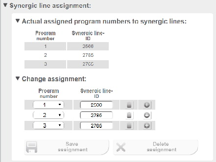
Website of the welding machine
Information on the use of the MIG/MAG standard manual, TIG, electrode, and ConstantWire welding processes
MIG/MAG standard manual
Use the MIG/MAG standard manual welding process:
During the standard manual welding process, the wire speed and welding voltage parameters are set as follows:1Select 2-step mode characteristics
2Select the MIG/MAG standard manual welding process using the appropriate characteristic number
- In order to set the Wire feed speed command value manual parameter, the Wire feed speed command value analog input signal must be used.
- In order to set the Welding voltage command value manual parameter, the Arc length correction analog input signal must be used.
- In order to set the Dynamic correction manual parameter, the Pulse-/dynamic correction analog input signal must be used.
- In order to set the Wire retract correction manual parameter, the Wire retract correction analog input signal must be used.
Use the TIG welding process:
1Select the TIG welding process using the appropriate characteristic number
Electrode
Use the electrode welding process:
1Select the electrode welding process using the appropriate characteristic number
ConstantWire
- ConstantWire can be used in conjunction with 2-step mode characteristics and Job Mode.
- With 2-step mode characteristics, the welding process is automatically defined via the selected characteristic.
- In Job Mode, the welding process is automatically defined via the selected job.
- The ConstantWire process starts as soon as the Welding start signal is set to High. Separately starting the wire movement and current flow is not required.
- The wire speed is specified with the Wire feed speed command value signal.
- The voltage limitation does not need to be set, because the automatic setting of the voltage limitation always ensures the current flow.
- If required, the voltage limitation can also be set manually (refer in this regard to the operating instructions for the respective welding machine).
Arc Break Monitoring
Arc break monitoring
The arc break monitoring is a function that can be activated on the welding machine. The function becomes active when arc breaks occur.
If the arc break monitoring becomes active due to an arc break, the Robot motion release signal is set to Low.
The following can be set in order to use the arc break monitoring:- The break length after which the arc break monitoring becomes active.
- In which way the arc break monitoring is activated
- With "Ignore"
- With "Error"
- If the arc breaks for 190 ms, the arc break monitoring is not activated.
- If the arc breaks for 210 ms, the welding machine reports an error message and stops the welding process.
- If the arc breaks for 190 ms, the arc break monitoring is not activated.
- If an arc breaks for 210 ms, the Arc stable signal is set to Low by the arc break monitoring. Whether the Welding start signal remains High or is set to Low by the robot depends on the setting selected on the robot.

Example of arc break monitoring behavior
(1) The status of the Welding start signal is dependent on:- The arc break monitoring setting.
- The robot setting (how the robot should react to the "Ignore" setting on the arc break monitoring).
- The robot sets the Welding start signal to Low (= no reignition of the arc), or
- Leaves the Welding start signal on High (= reignition of the arc)—depending on the robot setting.
- An error message is output and the welding process is stopped.
Arc break monitoring
The arc break monitoring is a function that can be activated on the welding machine. The function becomes active when arc breaks occur.
If the arc break monitoring becomes active due to an arc break, the Robot motion release signal is set to Low.
The following can be set in order to use the arc break monitoring:- The break length after which the arc break monitoring becomes active.
- In which way the arc break monitoring is activated
- With "Ignore"
- With "Error"
- If the arc breaks for 190 ms, the arc break monitoring is not activated.
- If the arc breaks for 210 ms, the welding machine reports an error message and stops the welding process.
- If the arc breaks for 190 ms, the arc break monitoring is not activated.
- If an arc breaks for 210 ms, the Arc stable signal is set to Low by the arc break monitoring. Whether the Welding start signal remains High or is set to Low by the robot depends on the setting selected on the robot.
Example of arc break monitoring behavior
(1) The status of the Welding start signal is dependent on:- The arc break monitoring setting.
- The robot setting (how the robot should react to the "Ignore" setting on the arc break monitoring).
- The robot sets the Welding start signal to Low (= no reignition of the arc), or
- Leaves the Welding start signal on High (= reignition of the arc)—depending on the robot setting.
- An error message is output and the welding process is stopped.
Fronius Data Channel
Fronius Data Channel
A variety of signals and data can be written and exchanged between the welding machine and a control unit (robot controller, etc.) via the Ethernet connection on the rear of the welding machine (service port).
In order to be able to use the Fronius Data Channel, OPT/i Documentation must be enabled for the welding machine.
On TWIN systems, the Ethernet connection socket on the welding machine of process line 1 must be used.
Available signals and data: | |||
|---|---|---|---|
Number | Designation | Description | Type of signal |
1 | Process active | 1/0 | Output |
2 | Current flow | 1/0 | Output |
3 | Article number | String | Input |
4 | Serial number | String | Input |
5 | Seam number | Integer | Input |
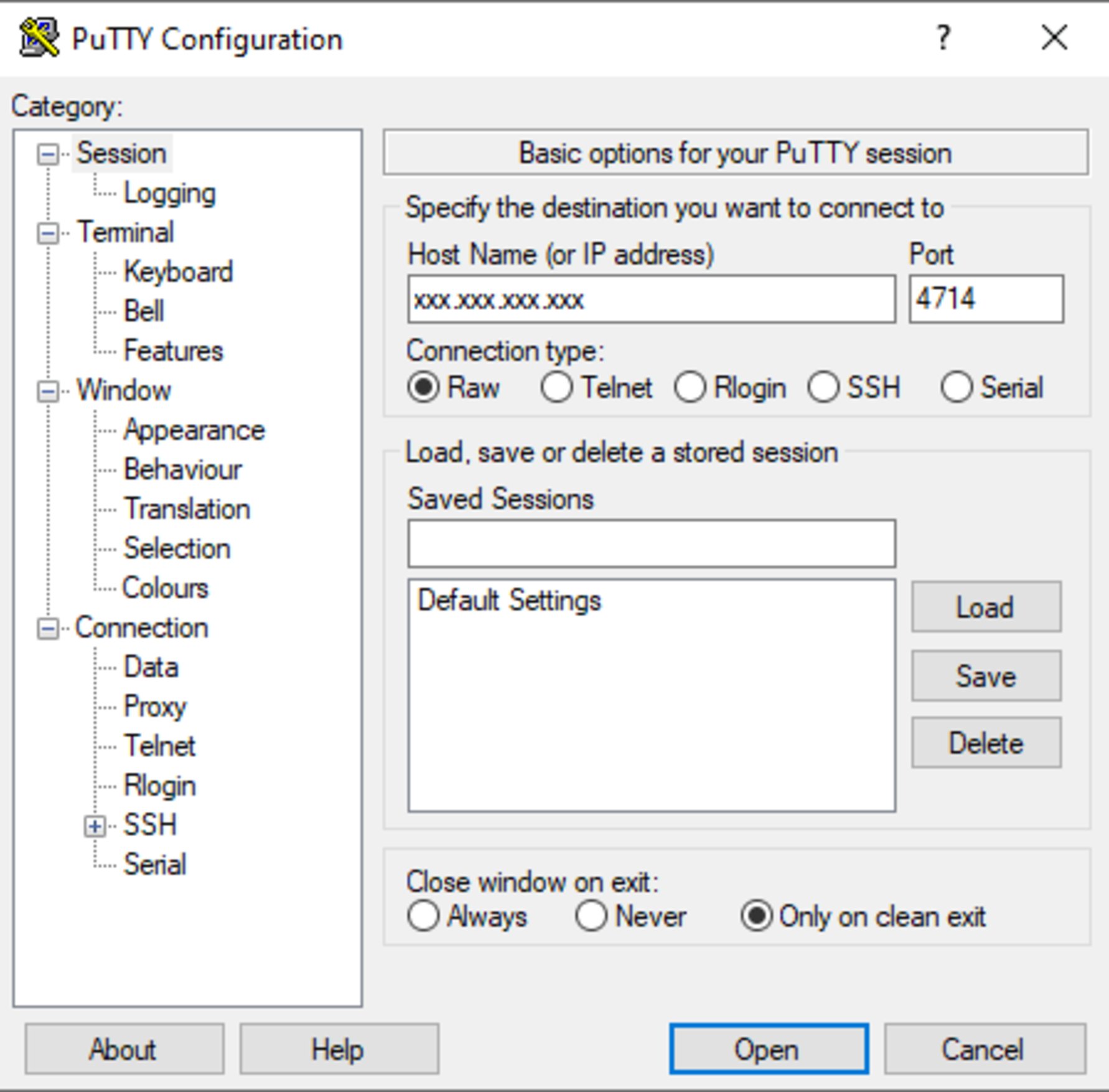
Windows example (PuTTY)
A TCP socket connection must be established for data transfer.
1For this purpose, enter the IP address of the welding machine service port and the port number 4714.
Fronius Data Channel
A variety of signals and data can be written and exchanged between the welding machine and a control unit (robot controller, etc.) via the Ethernet connection on the rear of the welding machine (service port).
In order to be able to use the Fronius Data Channel, OPT/i Documentation must be enabled for the welding machine.
On TWIN systems, the Ethernet connection socket on the welding machine of process line 1 must be used.
Available signals and data: | |||
|---|---|---|---|
Number | Designation | Description | Type of signal |
1 | Process active | 1/0 | Output |
2 | Current flow | 1/0 | Output |
3 | Article number | String | Input |
4 | Serial number | String | Input |
5 | Seam number | Integer | Input |
Windows example (PuTTY)
A TCP socket connection must be established for data transfer.
1For this purpose, enter the IP address of the welding machine service port and the port number 4714.
Signal sequence when selected using "Job Mode" operating mode

| (1) | Wait time of at least 0.1 seconds |
| (2) | Wait time of at least 0.1 seconds |
| (3) | Gas pre-flow time |
| (4) | Starting current time |
| (5) | Slope 1 |
| (6) | Gas post-flow time |
| (7) | Slope 2 + final current time |
| (1) | Wait time of at least 0.1 seconds |
| (2) | Wait time of at least 0.1 seconds |
| (3) | Gas pre-flow time |
| (4) | Starting current time |
| (5) | Slope 1 |
| (6) | Gas post-flow time |
| (7) | Slope 2 + final current time |
Signal sequence when selected using "Characteristics Mode" operating mode

| (1) | Wait time of at least 0.1 seconds |
| (2) | Wait time of at least 0.1 seconds |
| (3) | Wait time of at least 0.1 seconds |
| (4) | Gas pre-flow time |
| (5) | Starting current time |
| (6) | Slope 1 |
| (7) | Gas post-flow time |
| (8) | Slope 2 + final current time |
| (1) | Wait time of at least 0.1 seconds |
| (2) | Wait time of at least 0.1 seconds |
| (3) | Wait time of at least 0.1 seconds |
| (4) | Gas pre-flow time |
| (5) | Starting current time |
| (6) | Slope 1 |
| (7) | Gas post-flow time |
| (8) | Slope 2 + final current time |
WireSense - more information
Process description for WireSenseContour sensing

- Section WireSense start - Single Bit from page (→) and
- Section WireSense edge detection - Group Input / Analog Input from page (→) and
- Section WireSense break - Single Bit from page (→).
Process description for WireSenseContour sensing
- Section WireSense start - Single Bit from page (→) and
- Section WireSense edge detection - Group Input / Analog Input from page (→) and
- Section WireSense break - Single Bit from page (→).
Process description WireSense edge detection (edge detection)

- Section WireSense start - Single Bit from page (→) and
- Section WireSense edge detection - Group Input / Analog Input from page (→) and
- Section WireSense break - Single Bit from page (→).
Signal curve of Edge Detection Mode on a level surface

- No slag on the tip of the wire electrode:
The WireSense process starts without the WireSense -Slaghammer function and the Arc stable / Touch signal is output around 20 ms after the wire electrode touches the workpiece. - Slag present on the tip of the wire electrode:
Before starting the WireSensefunction, the WireSense -Slaghammer function is automatically activated to remove the slag residues from the tip of the wire electrode. The Arc stable / Touch signal is activated only after successful removal of the slag and sufficient electrical contact between the wire electrode and the workpiece. The delay time for the Arc stable / Touch signal can thus be many times greater than 20 ms.
Signal curve of Edge Detection Mode on a slanted surface

- No slag on the tip of the wire electrode:
The WireSense process starts without the WireSense -Slaghammer function and the Arc stable / Touch signal is output around 20 ms after the wire electrode touches the workpiece. - Slag present on the tip of the wire electrode:
Before starting the WireSensefunction, the WireSense -Slaghammer function is automatically activated to remove the slag residues from the tip of the wire electrode. The Arc stable / Touch signal is activated only after successful removal of the slag and sufficient electrical contact between the wire electrode and the workpiece. The delay time for the Arc stable / Touch signal can thus be many times greater than 20 ms.
Signal curve of Sensing Mode for different surface geometries

- No slag on the tip of the wire electrode:
The WireSense process starts without the WireSense -Slaghammer function and the Arc stable / Touch signal is output around 20 ms after the wire electrode touches the workpiece. - Slag present on the tip of the wire electrode:
Before starting the WireSensefunction, the WireSense -Slaghammer function is automatically activated to remove the slag residues from the tip of the wire electrode. The Arc stable / Touch signal is activated only after successful removal of the slag and sufficient electrical contact between the wire electrode and the workpiece. The delay time for the Arc stable / Touch signal can thus be many times greater than 20 ms.
Signal curve of WireSense break (during Sensing Mode)

- No slag on the tip of the wire electrode:
The WireSense process starts without the WireSense -Slaghammer function and the Arc stable / Touch signal is output around 20 ms after the wire electrode touches the workpiece. - Slag present on the tip of the wire electrode:
Before starting the WireSensefunction, the WireSense -Slaghammer function is automatically activated to remove the slag residues from the tip of the wire electrode. The Arc stable / Touch signal is activated only after successful removal of the slag and sufficient electrical contact between the wire electrode and the workpiece. The delay time for the Arc stable / Touch signal can thus be many times greater than 20 ms.
Representation of the possible WireSense-measurement range
Minimum and maximum possible wire movement in the WireSense contour sensing mode (Konturerkennung):

Minimum and maximum possible wire movement in the WireSense edge detection mode (Kantenerkennung):

WireSense edge detection mode without height measurement:
Analog input: WireSense-EdgeDetection = 1 mm
max. Forward WireMovement = WireSense-EdgeDetection + 3 mm
= 1 mm + 3 mm
= 4 mm

The wirefeeder stops the forward movement of the wire electrode after 4 mm, the wire electrode does not reach the lower sheet. It is therefore not possible to measure the height of the sheet edge.
However, the Touch signal is output as usual as soon as the EdgeDetection value has been exceeded.
This behavior can be undesirable, e.g., when measuring sheet edges.
Remedy:
set a value for the WireSenseEdgeDetection (Height) that is max. 2 mm less than the expected edge height to be measured.
For example, in the case of a 5 mm edge, this results in an EdgeDetction value of 3 mm.
In other applications, this behavior may be desired, e.g., in applications with an insulating weld pool support.
The component position is determined by the Touch signal, but the height is not measured.
It is important that the wire electrode stops before the insulating weld pool support and does not touch the weld pool support.
If the wire electrode touches the support, this will cause a malfunction in the WireSense process.

Application with insulating weld pool support (CERAMIC)
Note on ignition timeout (Ignition Timeout)
If the ignition timeout is set to 30 mm (1.18 inches), for example, but the end of the wire electrode is more than 30 mm (1.18 inches) away from the workpiece, the WireSense function will not start successfully because the wire feed is stopped after 30 mm (1.18 inches).

| (1) | For example, distance = 40 mm (1.57 inches) |
| (2) | Ignition timeout setting = after 30 mm (1.18 inches), for example |
Available signals for component scanning
Signal list
WireSense (contour detection): | ||||
|---|---|---|---|---|
Signal designation | Type of signal | Data type | Factor | Value range |
WireSense start | Input | BIT |
|
|
WireSense break | Input | BIT |
|
|
Wire position | Output | WORD (SINT) in mm | 100 | -327.68 to +327.67 |
WireSense Edge Detection (edge detection): | ||||
|---|---|---|---|---|
Signal designation | Type of signal | Data type | Factor | Value range |
WireSense start | Input | BIT |
|
|
Touch signal | Output | BIT |
|
|
WireSense Edge Detection (BIT 256-271) | Input | WORD (UINT) in mm | 10 | 0 to 20 mm |
Wire position | Output | WORD (SINT) in mm | 100 | -327.68 to +327.67 |
Teach mode: | ||||
|---|---|---|---|---|
Signal designation | Type of signal | Data type | Factor | Value range |
Teach Mode | Input | BIT |
|
|
Wire position | Output | WORD (SINT) in mm | 100 | -327.68 to +327.67 |
Touch signal | Output | BIT |
|
|
Limit Monitoring - functions and activation
Functions of Limit Monitoring
- Limit Monitoring monitors the welding parameters of the welding process.
- Limit Monitoring indicates whether the weld is performed within the predefined limit values of the weld specification (= job set values).
- If Limit Monitoring determines that the actual values are outside the defined limits, the weld seam should be checked.
- If the weld seam is OK in such a case, it is recommended to check the defined limits and adjust them if necessary.
- If the weld seam is not OK in such a case, it is recommended to check the welding parameters and adjust them if necessary.
- Limit Monitoring is only active in the main current phase.
- Limit Monitoring is not active during the Slope-phases.
- Limit Monitoring can only be used in conjunction with Job Mode.
Limit Monitoring does not monitor the quality of the weld seam. As a result, Limit Monitoring does not provide any information on whether the weld seam is OK or not.
Limit Monitoring is available for the following processes:- MIG/MAG standard synergic
- MIG/MAG pulse synergic
- MIG/MAG PMC
- MIG/MAG LSC
- CMT
- MIG/MAG PMC Mix
- CMT Mix
- CMT Cycle Step
- SynchroPulse welding with
- MIG/MAG standard synergic
- MIG/MAG pulse synergic
- MIG/MAG PMC
- MIG/MAG LSC
Available function packages
Among other things, to monitor:
- Voltage
- Current
- Wirefeeder
- Welding time
- Energy
- Enables remote access (for example from a PC) to the welding machine (Smart Manager). For example, the limit values of job parameters can be changed via the Smart Manager; directly from the PC, without having to implement the setting at the welding machine itself.
- Is used to export the welding data stored in the welding machine as a CSV file, in addition to the export as a PDF file available by default.
- Enables the use of FroniusDataChannel, which is used for the exchange of Traceability data.
Prerequisites for the successful use of Limit Monitoring
- Job mode must be enabled for each welding machine.
- At least 1 job must be assigned to each weld seam
- It is recommended to use several jobs per weld seam if significant influencing factors change during welding, such as robot speed, angle of attack of the welding torch, Stick-Out, etc.
- Only create jobs when the correct welding parameters have already been determined
- If the welding parameters in the job are changed, the limits must also be adjusted accordingly.
- Always set limits based on measured actual values (not based on set values). The following options are available
- Read actual values on the display of the welding machine during welding.
- Read actual values via the Smart Manger during welding.
- Evaluation of the welding parameters by means of WeldCube Premium.
Switch Limit Monitoring on / off
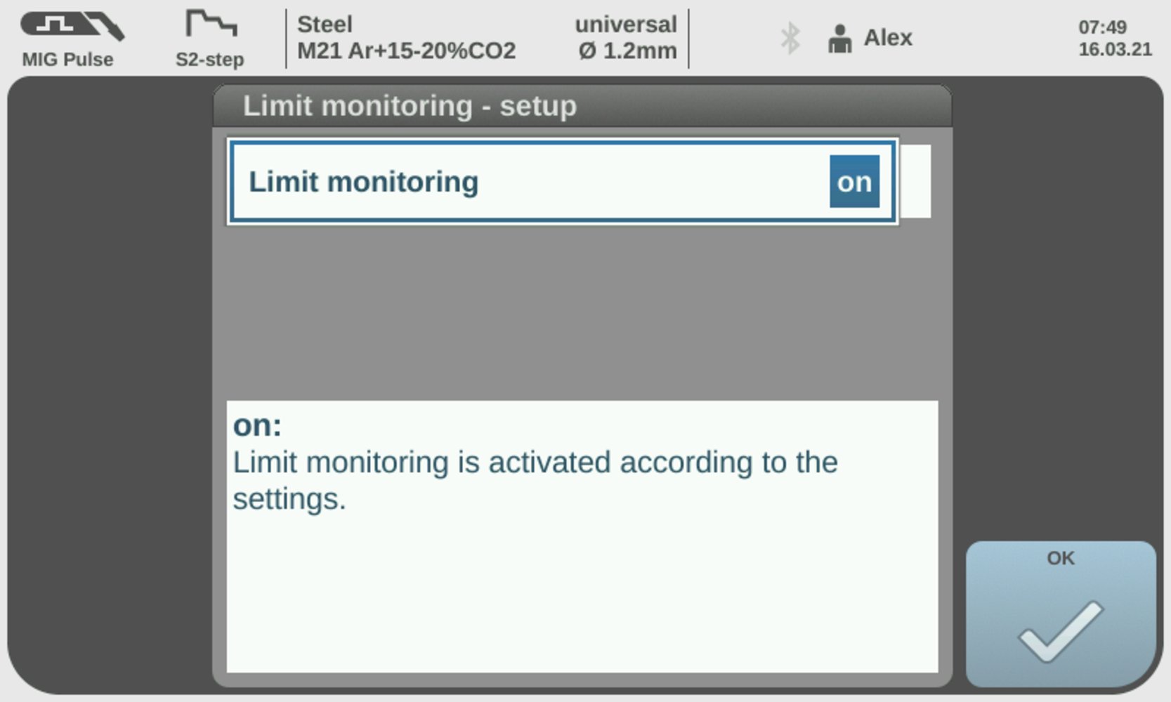
Limit Monitoring on
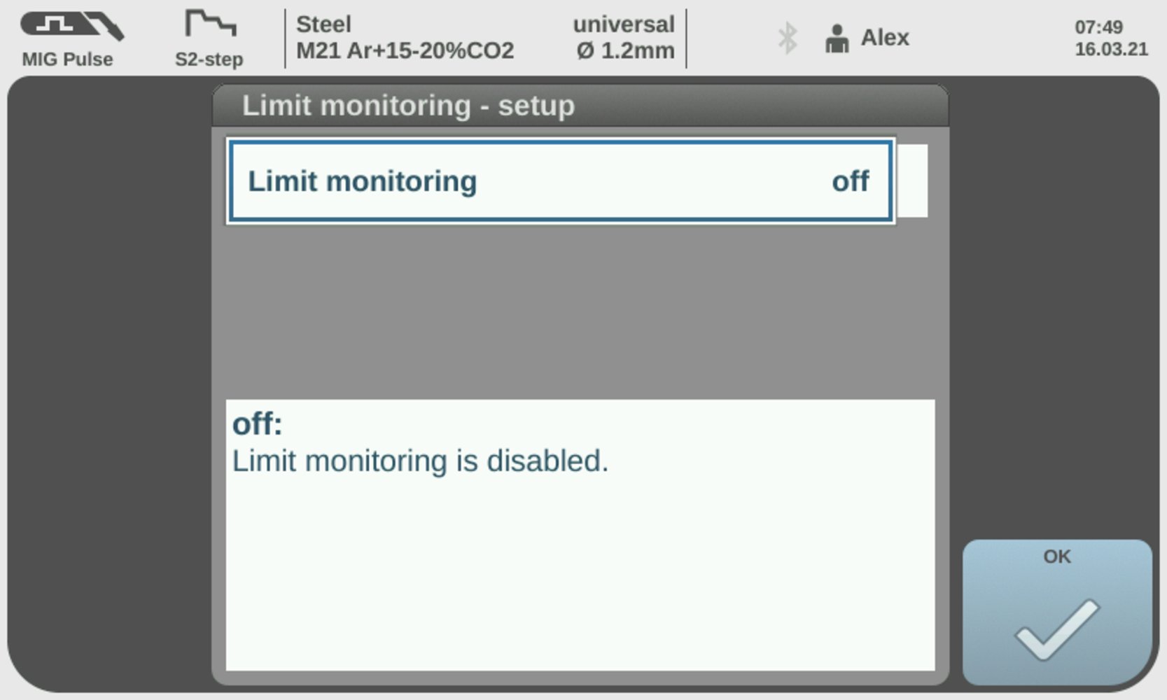
Limit Monitoring off
Detailed description of Limit Monitoring
- Limit Monitoring is only active in the main current phase.
- The data is recorded / checked every 50 ms during Limit Monitoring.
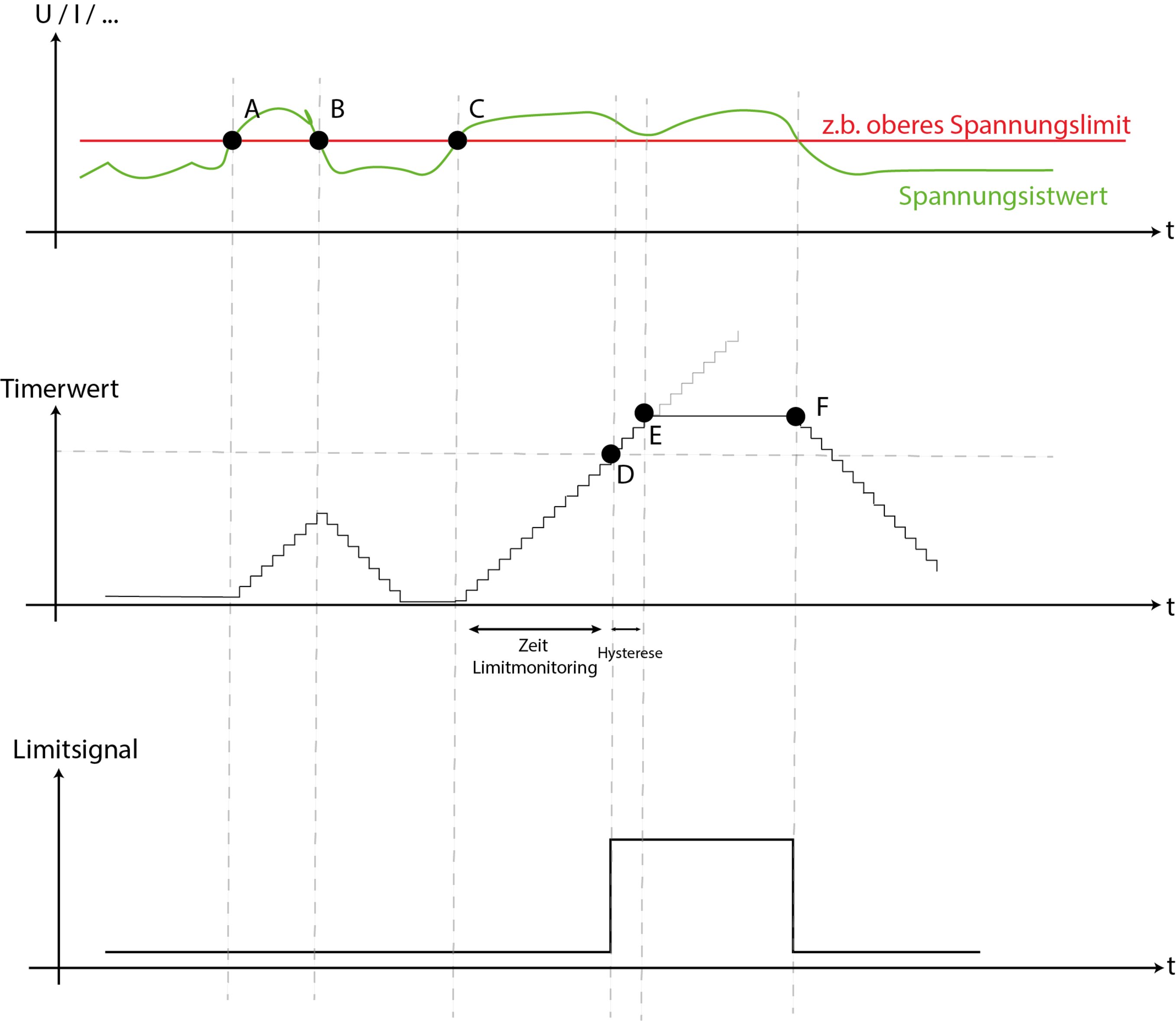
- At point A, the upper voltage limit is exceeded; the time until the reaction of Limit Monitoring begins to count constantly upwards.
- At point B, the voltage falls below the upper limit again; the time until the reaction of Limit Monitoring counts down to 0.
- At point C, the upper voltage limit is exceeded again; the time until the reaction of Limit Monitoring starts to count upwards constantly again.
- At point D, the set time limit for the reaction of limit monitoring is reached:
- The hysteresis time starts to run.
- Point E shows the hysteresis of +20% to the set time value (time until reaction from Limit Monitoring).
- A warning or an error is issued depending on the setting.
- The Limitsignal (Word 1 / Byte 2 / Bit 19) changes to High.
- At point F, the Limitsignal (Word 1 / Byte 2 / Bit 19) changes to Low.
- With energy monitoring, Limit Monitoring does not monitor each job individually, but the entire weld seam - for more information see Energy monitoring from page (→).
- With welding time monitoring, Limit Monitoring does not monitor each job individually, but the entire weld seam - for more information see Welding time monitoring from page (→).
Limit Monitoring - details on the individual welding parameters
Voltage monitoring
- Set the voltage set value and the desired limits.
- Monitor the voltage actual value per weld seam / job.
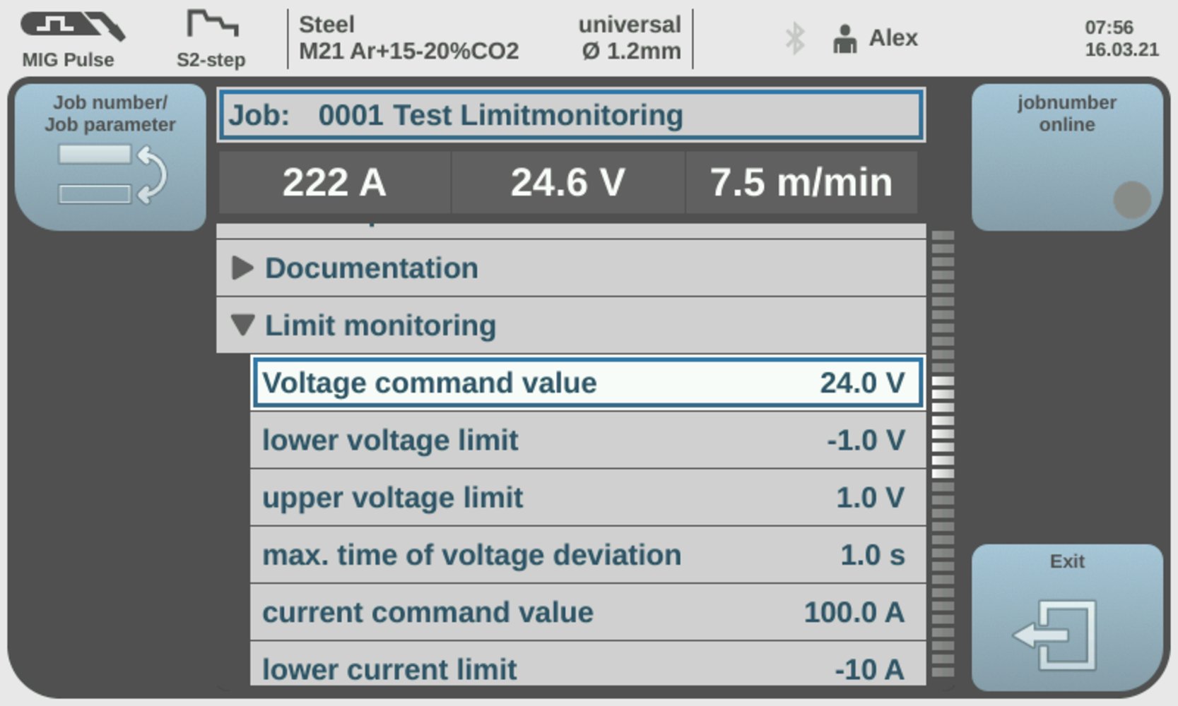
Voltage monitoring
Adjustable parameters:
| (1) | Voltage set value: 0 to 100 V |
| (2) | Lower voltage limit: -10 to 0 V |
| (3) | Upper voltage limit: 0 to 10 V |
| (4) | Time limit for the reaction of Limit Monitoring: Off / 0 to 10 seconds Explanation for setting from 0 to 10 seconds:
|
Possible error messages during voltage monitoring: | |
19 | | Lower voltage limit undershot |
20 | | Upper voltage limit exceeded |
Voltage monitoring
- Set the voltage set value and the desired limits.
- Monitor the voltage actual value per weld seam / job.
Voltage monitoring
Adjustable parameters:
| (1) | Voltage set value: 0 to 100 V |
| (2) | Lower voltage limit: -10 to 0 V |
| (3) | Upper voltage limit: 0 to 10 V |
| (4) | Time limit for the reaction of Limit Monitoring: Off / 0 to 10 seconds Explanation for setting from 0 to 10 seconds:
|
Possible error messages during voltage monitoring: | |
19 | | Lower voltage limit undershot |
20 | | Upper voltage limit exceeded |
Current monitoring
- Set the current set value and the desired limits.
- Monitor the current actual value per weld seam / job.
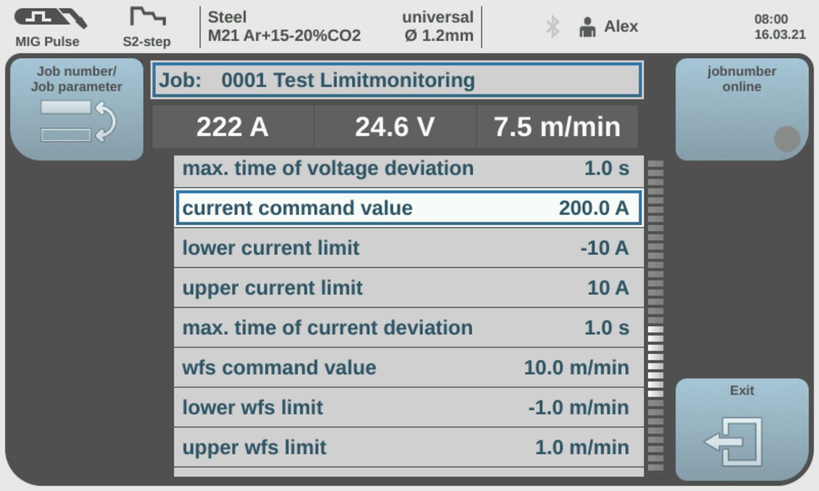
Current monitoring
Adjustable parameters:
| (1) | Current set value: 0 to 100 A |
| (2) | Lower current limit: -10 to 0 A |
| (3) | Upper current limit: 0 to 10 A |
| (4) | Time limit for the reaction of Limit Monitoring: Off / 0 to 10 seconds Explanation for setting from 0 to 10 seconds:
|
Possible error messages during current monitoring: | |
21 | | Lower current limit undershot |
22 | | Upper current limit exceeded |
Wirefeeder monitoring
- Set the wirefeeder set value and the desired limits.
- Monitor the wirefeeder actual value per weld seam / job.
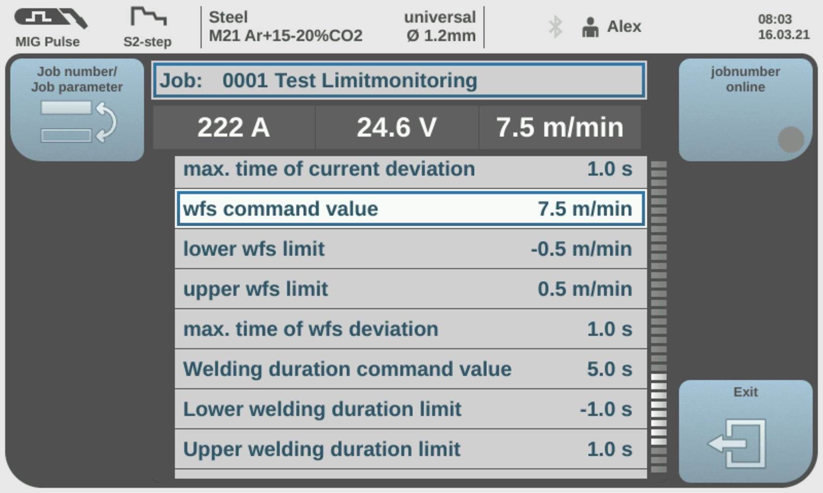
Wirefeeder monitoring
Adjustable parameters:
| (1) | Wirefeeder set value: 0 to 100 m/min |
| (2) | Lower wirefeeder limit: -10 to 0 m/min |
| (3) | Upper wirefeeder limit: 0 to 10 m/min |
| (4) | Time limit for the reaction of Limit Monitoring: Off / 0 to 10 seconds Explanation for setting from 0 to 10 seconds:
|
Possible error messages during wirefeeder monitoring: | |
23 | | Lower wirefeeder limit undershot |
24 | | Upper wirefeeder limit exceeded |
Welding time monitoring
- Set the welding time set value and the desired limits.
- Monitor the welding time per weld seam / job.
If a weld seam consists of 2 or more jobs, the welding time of the previously welded job must be added for the jobs following in the welding sequence.
Example:- A weld seam consists of 4 jobs, each with a duration of 4 seconds.
- Limit Monitoring ignores the first 3 jobs and only records the last job.
- For this reason, a welding time set value of at least 16 seconds must be set for the last job (4 x 4 seconds) in order to prevent Limit Monitoring from unintentionally issuing a notification.
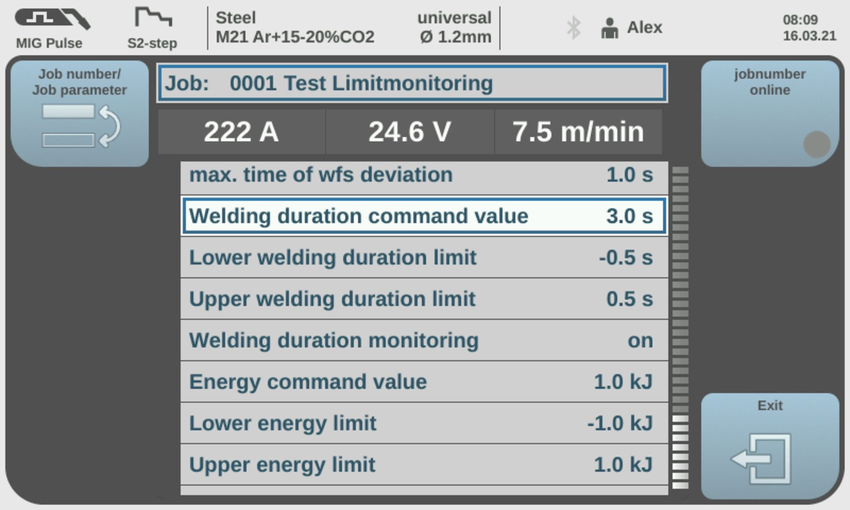
Welding time monitoring
Adjustable parameters:
| (1) | Welding time set value: 0 to 999.9 seconds |
| (2) | Lower welding time limit: -50 to 0 seconds |
| (3) | Upper welding time limit: 0 to 50 seconds |
| (4) | Time limit for the reaction of Limit Monitoring: Off / 0 to 10 seconds Explanation for setting from 0 to 10 seconds:
|
Possible error messages during welding time monitoring: | |
50 | | Lower welding time limit not reached |
51 | | Upper welding time limit exceeded |
Energy monitoring
- Set the energy set value and the desired limits.
- Monitor the energy input per weld seam / job.
If a weld seam consists of 2 or more jobs, the energy input of the previously welded job must be added for the subsequent jobs in the weld sequence.
Example:- A weld seam consists of 4 jobs, with an energy input of 40 kJ each.
- Limit Monitoring ignores the first 3 jobs and only records the last job.
- For this reason, an energy set value of at least 160 kJ must be set for the last job (4 x 40 kJ) in order to prevent Limit Monitoring from unintentionally issuing a notification.
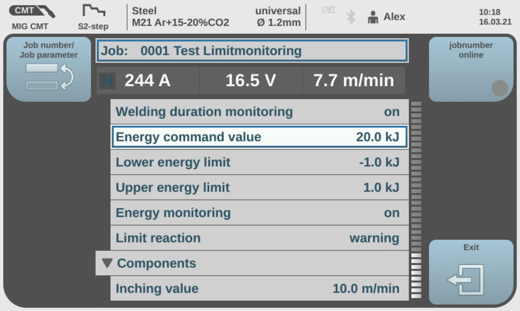
Energy monitoring
Adjustable parameters:
| (1) | Energy set value: 0 to 9999.9 kJ |
| (2) | Lower energy limit: -10 to 0 kJ |
| (3) | Upper energy limit: 0 to 10 kJ |
| (4) | Energy monitoring: On/Off |
Possible error messages: | |
47 | | Lower energy limit not reached |
48 | | Upper energy limit exceeded |
Setting of the reaction when exceeding or falling below the limits:
- Determination of how the welding machine reacts when the set limits are exceeded or not reached.
- Ignore
- Warning
- Error
The following is a description of each reaction.
Reaction when limits are exceeded or undershot = ignore:- No reaction
- No entry in the logbook

Reaction when limits are exceeded or undershot = Ignore
- Entry is made in the logbook.
- The welding parameters affected by exceeding or falling below the limits are marked in red.

Reaction when limits are exceeded or undershot = Warning
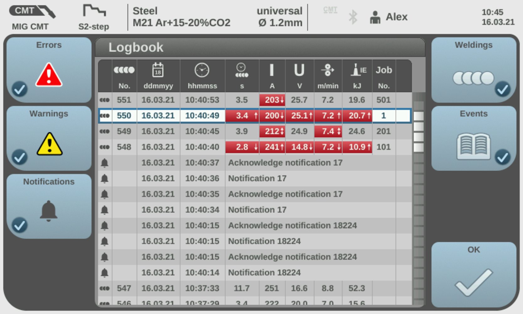
Overview of the entries in the logbook
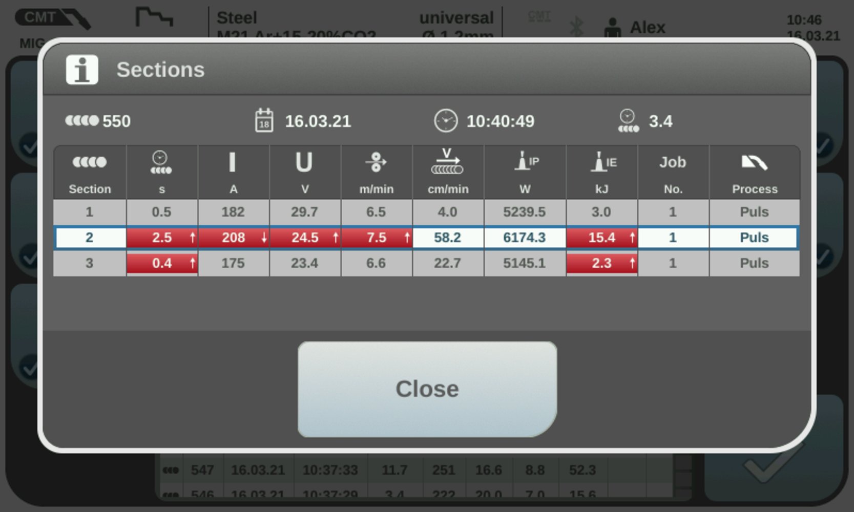
Display of the individual sections in the logbook
- The welding machine indicates whether the limits have been overrun or undershot.
- The overrun or undershoot is displayed until the end of welding.
- The welding parameters affected by exceeding or falling below the limits are marked in red.
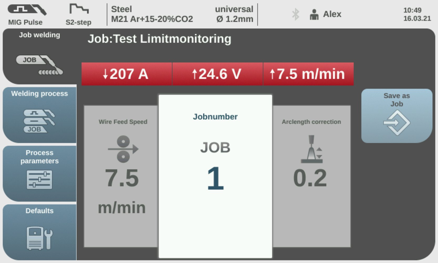
Display of the warning with the welding parameters
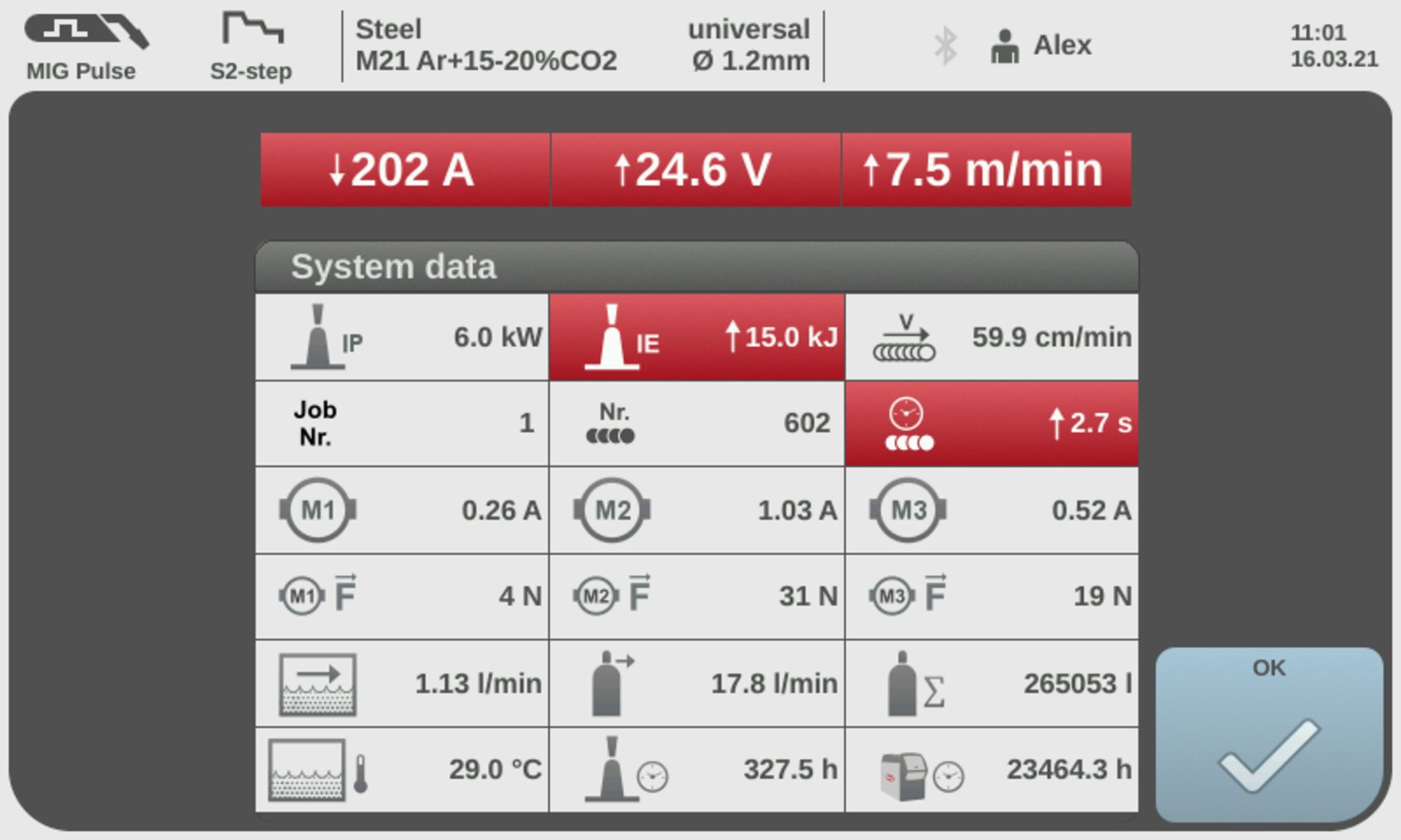
Display of the warning with the system data
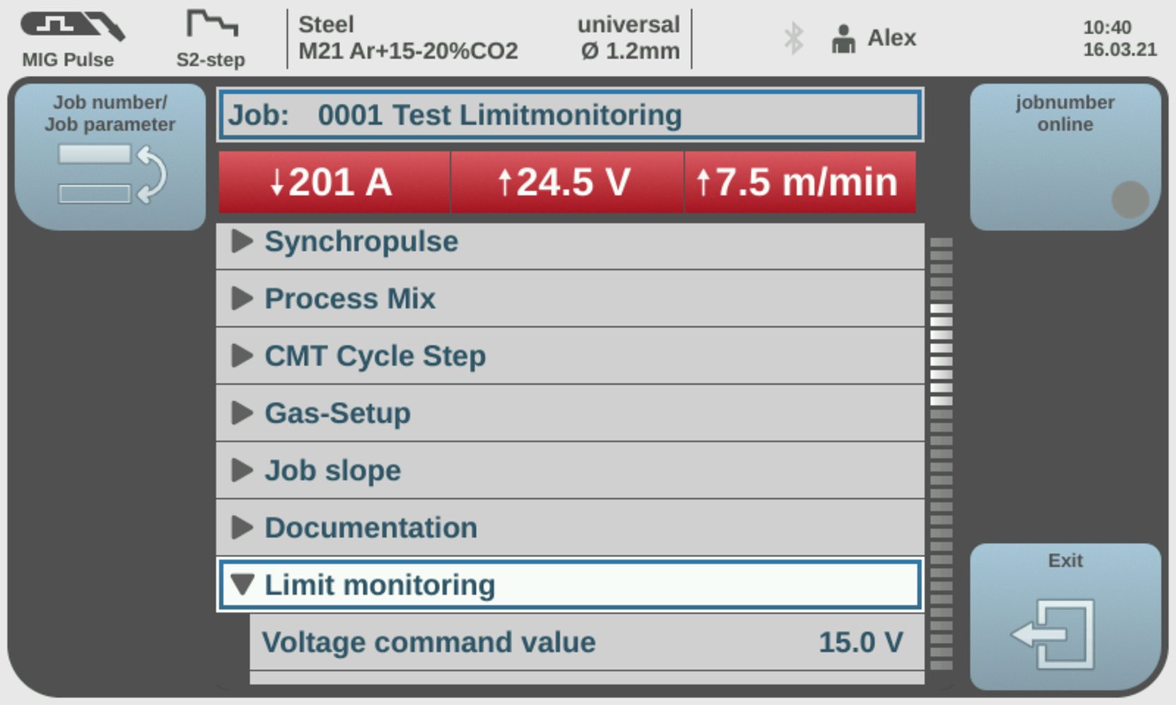
Display of the warning with Job optimization
- During welding, the limit signal (WORD 1 / Byte 2 / Bit 19) reacts directly to exceeding or falling below the limits
- If no overshoot or undershoot of the limits is detected, the Limitsignal Low remains.
- If an overshoot or undershoot of the limits is detected, the Limitsignal changes to High.
- As soon as the welding parameters are within the defined limits again, the Limitsignal changes back to Low after 1 second.
- No warning number is output at the interface (WORD 9 / Byte 18 - 19 / Bit 144 - 159).

Indicator on the interface; Limitsignal = Low

Indicator on the interface; Limitsignal = High
- Welding machine stops the welding process.
- Entry is made in the logbook.
- The welding parameters affected by exceeding or falling below the limits are marked in red.
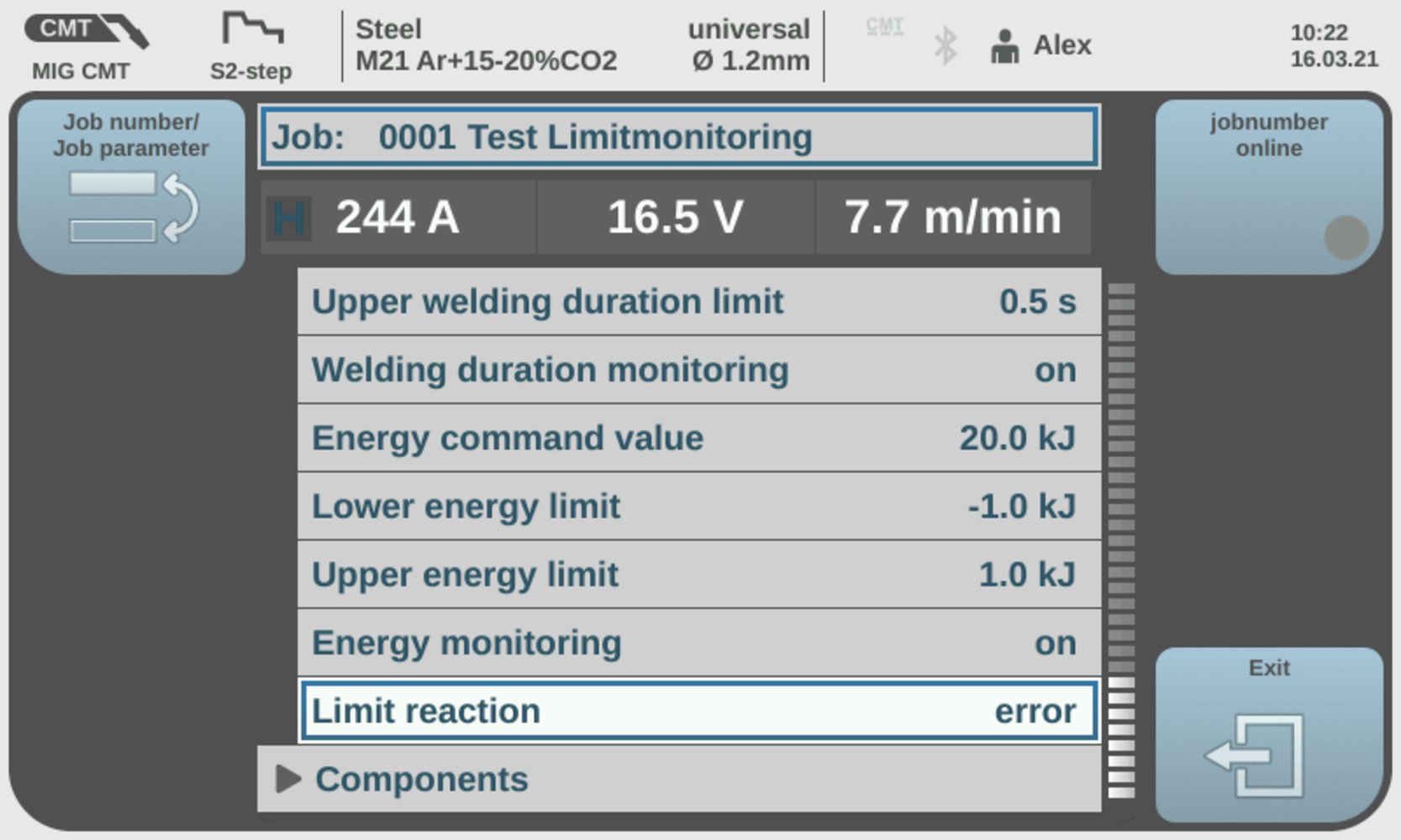
Reaction when limit exceeded / limit undershot = error
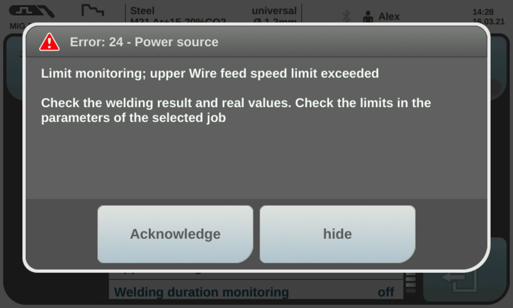
Error message
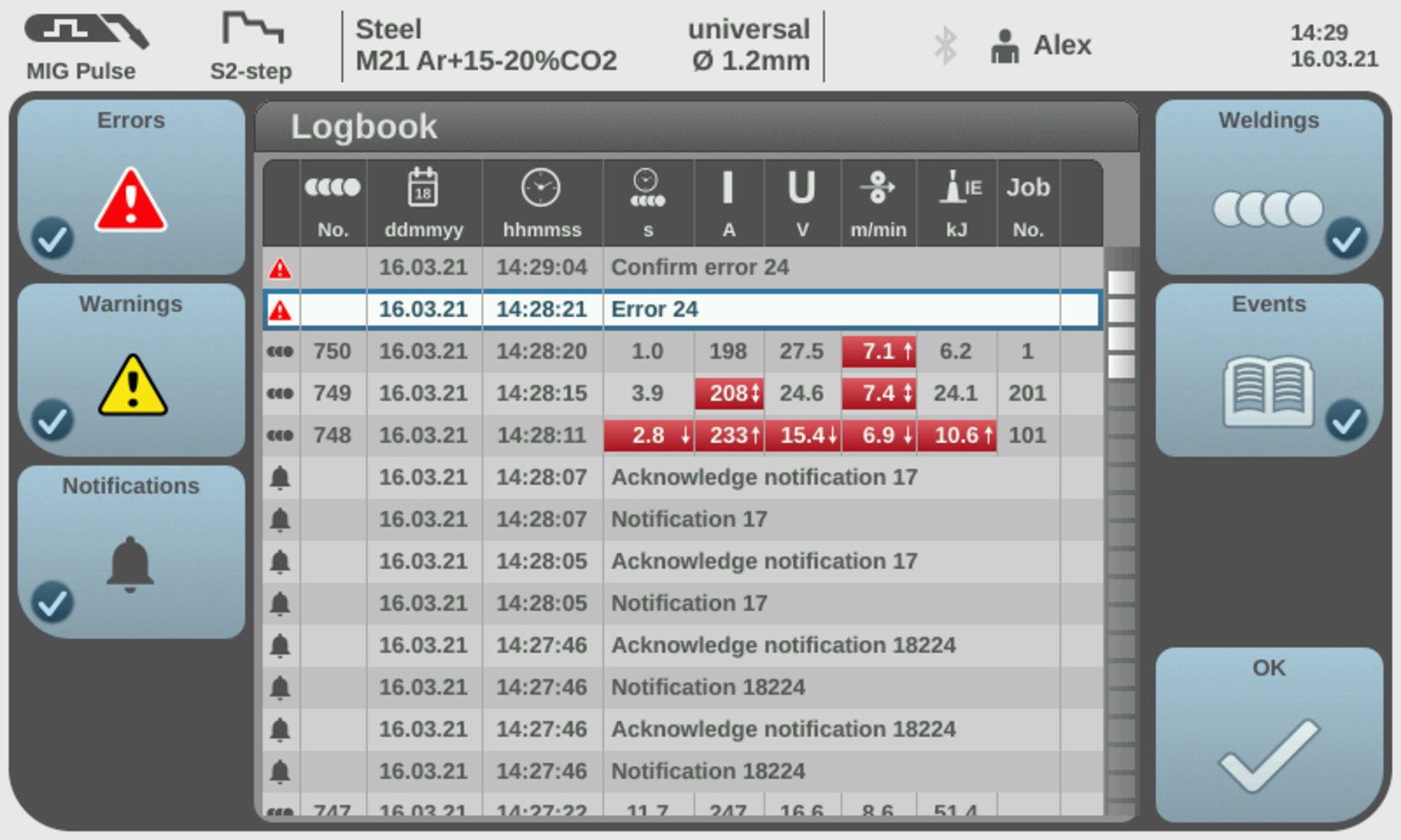
Overview of the entries in the logbook
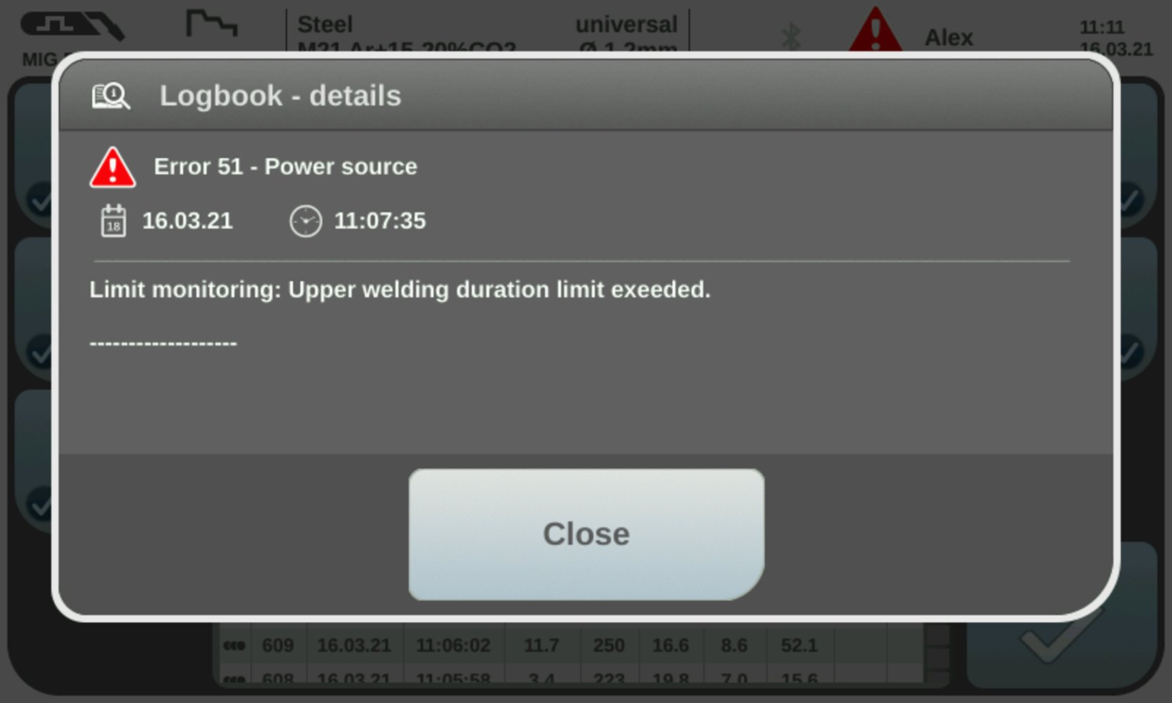
Logbook details
- During welding, the limit signal (WORD 1 / Byte 2 / Bit 19) reacts directly to exceeding or falling below the limits.
- If no overshoot or undershoot of the limits is detected, the Limitsignal Low remains.
- If an overshoot or undershoot of the limits is detected, the Limitsignal changes to High
- Welding is stopped immediately.
- The error number (= reason for the welding stop) can be read out at the interface (WORD 8 / Byte 16 - 17 / Bit 128 - 134).
- As soon as the welding parameters are within the defined limits again, the Limitsignal changes back to Low after 1 second.

Indicator on the interface; Limitsignal = Low
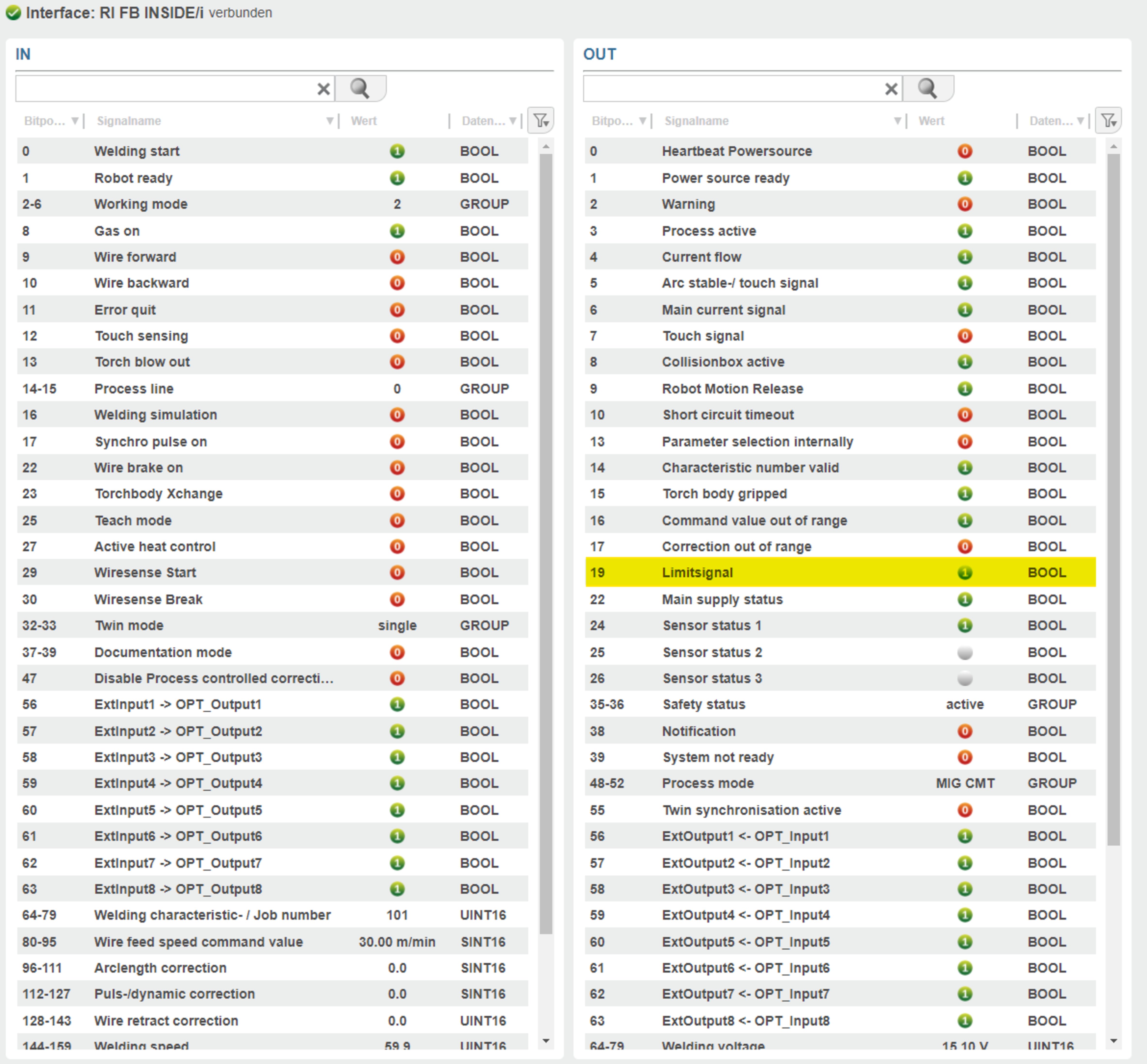
Indicator on the interface; Limitsignal = High
Overview of the interface functionalities in case of exceeding or falling below the limits:
Set reaction | Limit signal | Error number (WORD 8 / Byte 16 - 17 / Bit 128 - 134) | Warning number (WORD 9 / Byte 18 - 19 / Bit 144 - 159) | Stop welding: yes / no |
|---|---|---|---|---|
Ignore | - | - | - | - |
Warning | x | - | - | - |
Error | x | x | - | Yes |
Setting of the reaction when exceeding or falling below the limits for the motor force
- Motor force monitoring is not linked to a job and is therefore always available.
- In order to draw conclusions about the condition of the wire feed section (wear of the inner liner, condition of the motor, etc.), the motor force can be monitored and a corresponding reaction can be set if the defined limits are exceeded or undershot.
- Motor force monitoring is available from version 2.3.1 of the welding machine onwards.
- The motor force of the main motor M1 is monitored.
- Motor force monitoring is also active during the threading process.
- Determination of how the welding machine reacts when the set limit for the motor force is exceeded or undershot.
- Ignore
- Warning
- Error
The following is a description of each reaction.
Reaction when limits are exceeded or undershot = ignore:- No reaction at the welding machine.
- No entry is made in the logbook.
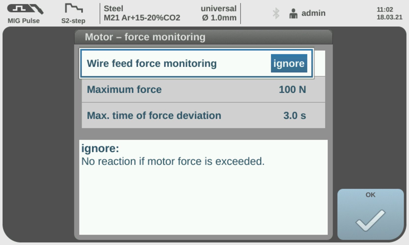
Reaction when limits are exceeded or undershot = Ignore
- The welding parameters affected by exceeding or falling below the limits are marked in red.
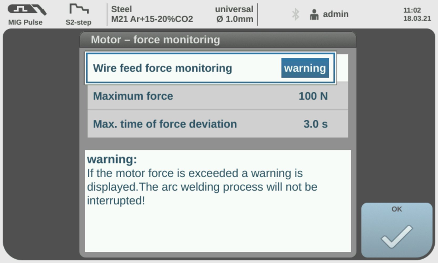
Reaction when limits are exceeded or undershot = Warning
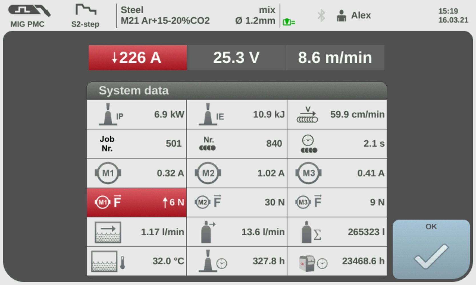
Display of the warning with the system data
- During welding, the limit signal (WORD 1 / Byte 2 / Bit 19) reacts directly to exceeding or falling below the limits
- If no overshoot or undershoot of the limits is detected, the Limitsignal Low remains.
- If an overshoot or undershoot of the limits is detected, the Limitsignal changes to High.
- As soon as the welding parameters are within the defined limits again, the Limitsignal changes back to Low after 1 second.
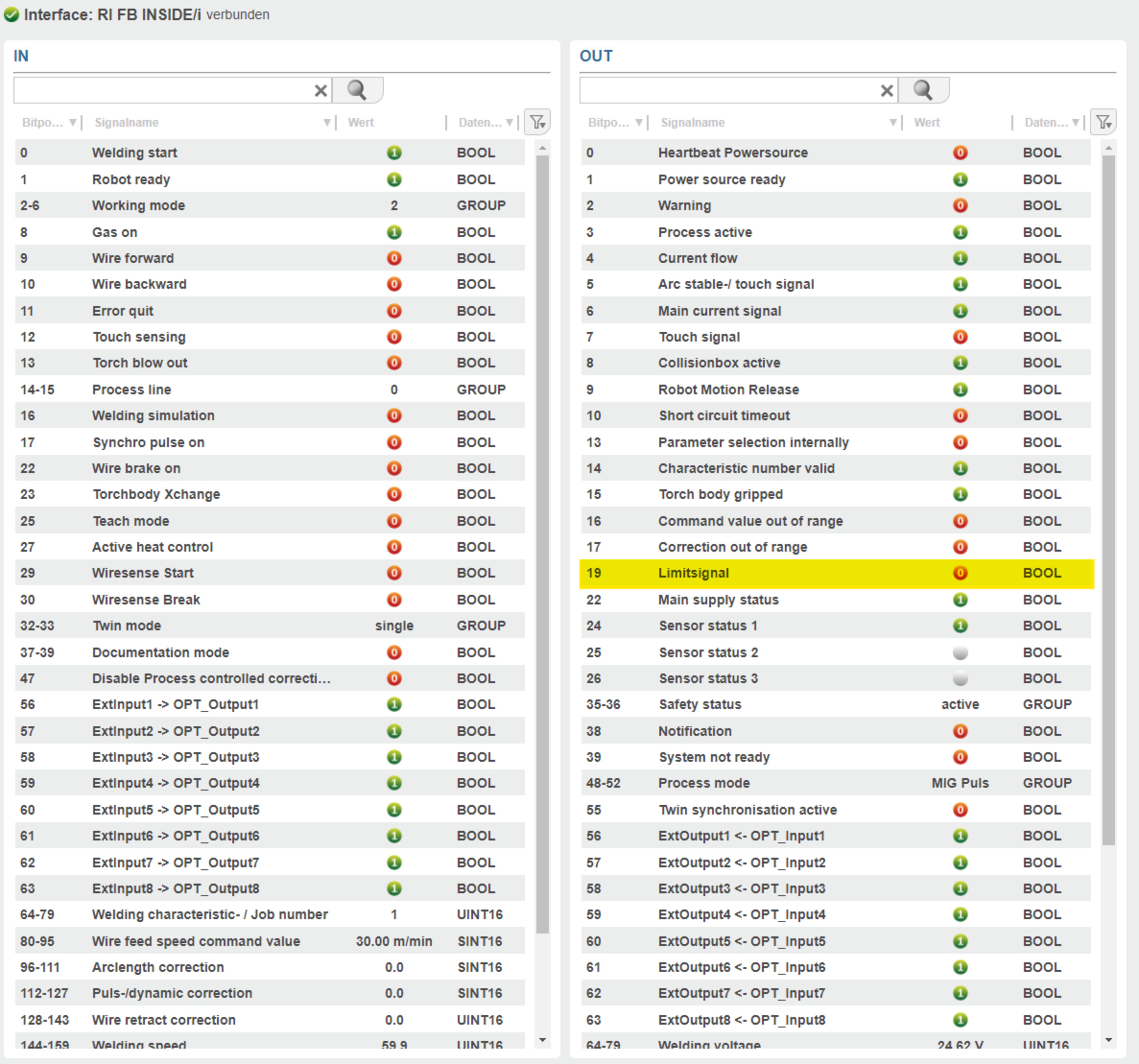
Indicator on the interface; Limitsignal = Low

Indicator on the interface; Limitsignal = High
- Welding machine stops the welding process.
- Entry is made in the logbook.
- The welding parameters affected by exceeding or falling below the limits are marked in red.
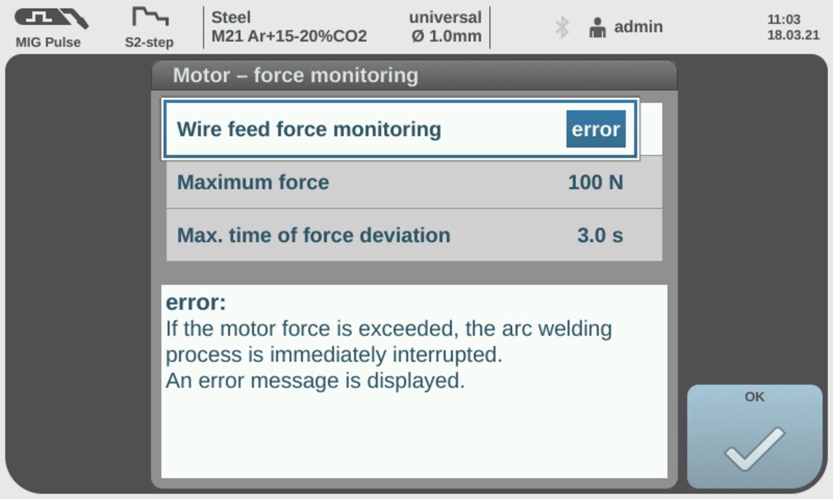
Reaction when limits are exceeded or undershot = Error
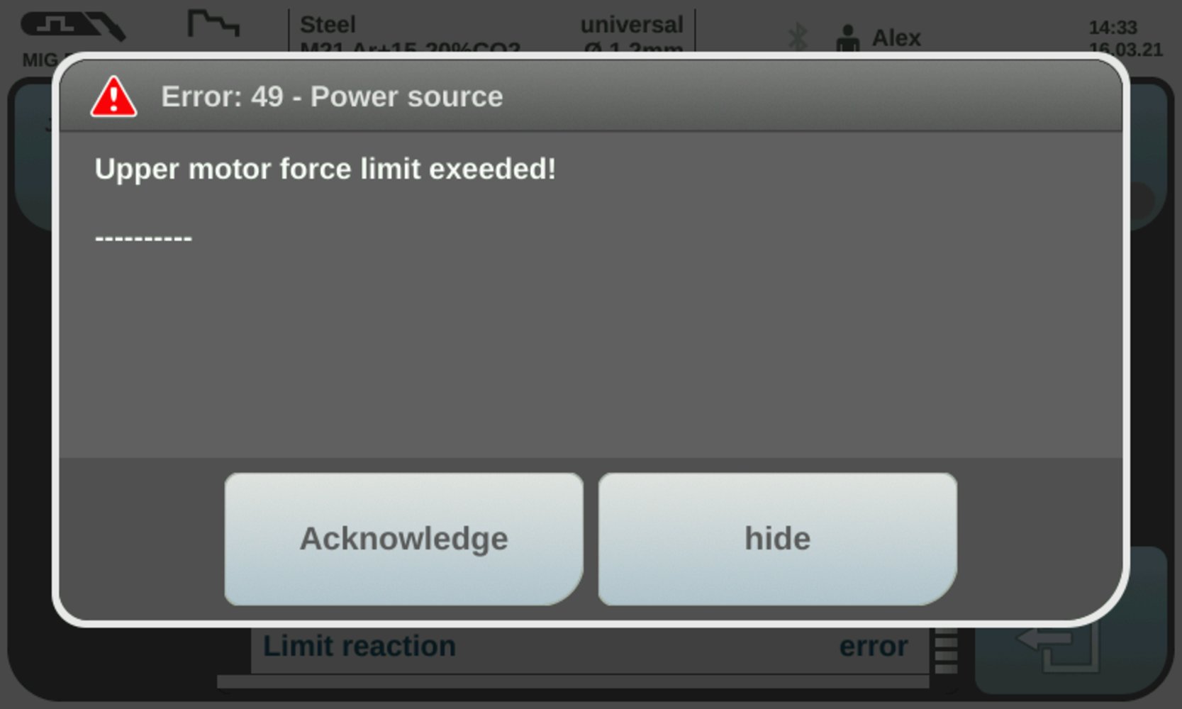
Error message
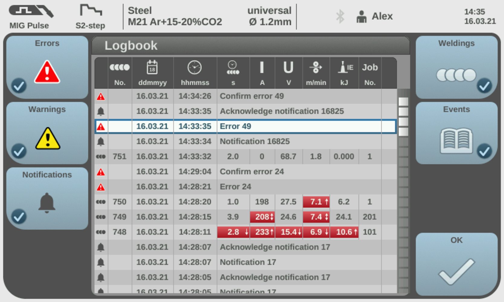
Overview of the entries in the logbook
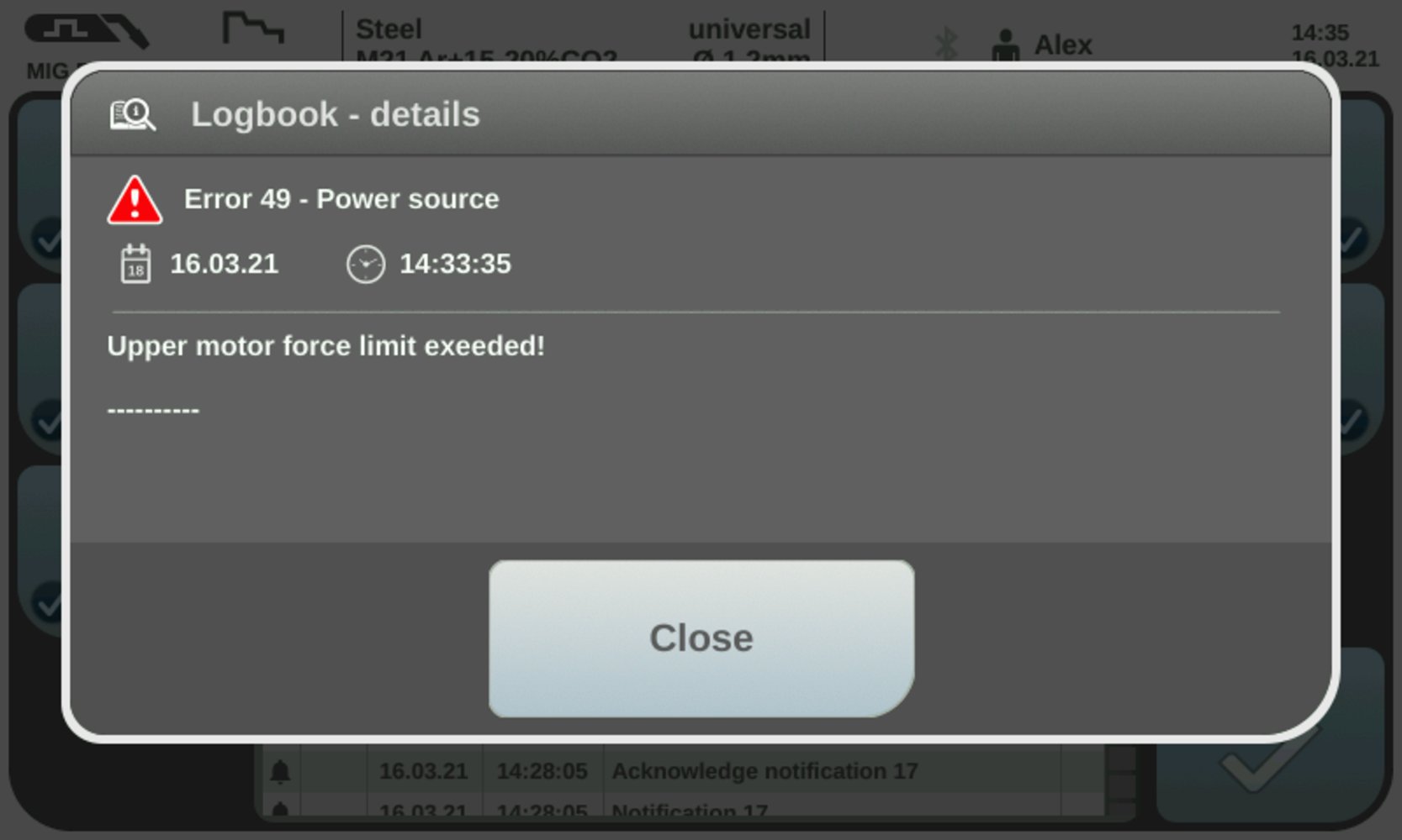
Logbook details
- During welding, the limit signal (WORD 1 / Byte 2 / Bit 19) reacts directly to exceeding or falling below the limits.
- If no overshoot or undershoot of the limits is detected, the Limitsignal Low remains.
- If an overshoot or undershoot of the limits is detected, the Limitsignal changes to High
- Welding is stopped immediately.
- The error number (= reason for the welding stop) can be read out at the interface (WORD 8 / Byte 16 - 17 / Bit 128 - 134).
- As soon as the welding parameters are within the defined limits again, the Limitsignal changes back to Low after 1 second.

Indicator on the interface; Limitsignal = Low

Indicator on the interface; Limitsignal = High
Smart Manager + OPT/i Jobs (4,067,002)
If the function package OPT/i Jobs has been activated, the desired limits can also be defined via the Smart Manager:
Define limit in Smart Manager
Information on exceeding or falling below limits is also displayed in the Smart Manager :
Smart Manager
Smart Manager
Display of overshooting or undershooting limits in the system data display of the Smart Manager:
System data display in the Smart Manager
The welding parameters affected by exceeding or falling below the limits are marked in red.