Safety Instructions
Explanation of Safety Instructions
DANGER!
Indicates an immediate danger.
Death or serious injury may result if appropriate precautions are not taken.
WARNING!
Indicates a possibly dangerous situation.
Death or serious injury may result if appropriate precautions are not taken.
CAUTION!
Indicates a situation where damage or injury could occur.
Minor injury or damage to property may result if appropriate precautions are not taken.
NOTE!
Indicates the possibility of flawed results and damage to the equipment.
Explanation of Safety Instructions
DANGER!
Indicates an immediate danger.
Death or serious injury may result if appropriate precautions are not taken.
WARNING!
Indicates a possibly dangerous situation.
Death or serious injury may result if appropriate precautions are not taken.
CAUTION!
Indicates a situation where damage or injury could occur.
Minor injury or damage to property may result if appropriate precautions are not taken.
NOTE!
Indicates the possibility of flawed results and damage to the equipment.
General
NOTE!
The WeldCube Connector is integrated into an existing welding system for data collection.
Therefore, all safety and warning notices relevant to the welding process apply to the WeldCube Connector.
Observe the Operating Instructions for all system components of the welding system, in particular the safety instructions and warning notices!
- Serious or fatal injury to the operator or third parties
- Damage to the device and other material assets belonging to the operating company
- Inefficient operation of the device
- Be suitably qualified
- Have knowledge of welding and
- Have fully read and precisely followed these Operating Instructions
The Operating Instructions must always be kept to hand wherever the device is being used. In addition to the Operating Instructions, all applicable local rules and regulations regarding accident prevention and environmental protection must also be followed.
All safety and danger notices on the device:- Must be kept in a legible state
- Must not be damaged/marked
- Must not be removed
- Must not be covered, pasted, or painted over
For the location of the safety and danger notices on the device, refer to the section headed "General Information" in the operating instructions for the device.
Before switching on the device, eliminate any faults that could compromise safety.
Your personal safety is at stake!
Intended use
The device is intended exclusively for measuring welding data in the designated power range as shown on the rating plate.
The device must be properly installed and set up to ensure it functions as intended.
Utilization for any other purpose, or in any other manner, shall be deemed to be not in accordance with the intended purpose. The manufacturer accepts no liability for any damage resulting from improper use.
Intended use also means- Reading and adhering to all instructions in the Operating Instructions
- Carefully reading and obeying all safety instructions and danger notices
- Carrying out all the specified inspection and maintenance work.
- Thawing pipes
- Charging batteries
- Starting motors
The manufacturer shall not be liable for faulty or incorrect work results.
Grid Connection
Devices with a high output can influence the energy quality of the grid due to their current consumption.
This may affect a number of device types in terms of:- connection restrictions
- criteria regarding maximum permissible grid impedance *)
- criteria regarding the minimum required short-circuit power *)
*) both at the interface with the public grid
See technical data
In this case, the operator or the person using the device should check whether or not the device is allowed to be connected, where appropriate through discussion with the power supply company.
IMPORTANT! Ensure secure grounding of the grid connection!
Environmental Conditions
Operation or storage of the device outside the stipulated area will be deemed as not in accordance with the intended purpose. The manufacturer accepts no liability for any damage resulting from improper use.
Temperature range of the ambient air:- During operation: -10°C to +40°C (14°F to 104°F)
- During transport and storage: -20°C to +55°C (-4°F to 131°F)
- Up to 50% at 40°C (104°F)
- Up to 90% at 20°C (68°F)
Ambient air: free of dust, acids, corrosive gases or substances, etc.
Altitude above sea level: up to 2000 m (6561 ft. 8.16 in.)
Obligations of the Operating Company
- Are familiar with the basic occupational safety and accident prevention regulations and are trained in handling the device
- Have read and understood these Operating Instructions, especially the section "Safety Rules," and have confirmed this with their signature
- Are trained according to the requirements for the work results
The safety-conscious work of the personnel must be checked regularly.
Obligations of Personnel
- Follow the basic regulations for occupational safety and accident prevention
- Read these Operating Instructions, especially the section "Safety Rules," and confirm that they have understood and will follow them by signing
Before leaving the workplace, ensure that no personal injury or property damage can occur in one's absence.
Residual current circuit breaker
Local regulations and national guidelines may mean that a residual current circuit breaker is required when connecting a device to the public grid.
The residual current circuit breaker recommended for the device by the manufacturer can be found in the technical data.
Personal Protection and Protection of Others
- Flying sparks and pieces of hot metal
- Arc radiation that poses a risk of injury to the eyes and skin
- Hazardous electromagnetic fields that pose a risk of death for individuals with pacemakers
- Electrical risks from grid current and welding current
- Increased noise exposure
- Harmful welding fumes and gases
- Flame resistant
- Insulating and dry
- Covering the entire body and in good condition with no damage
- Safety helmet
- Cuffless pants
- Protecting the face and eyes from UV radiation, heat and flying sparks with a face guard featuring a regulation-compliant filter
- Wearing regulation-compliant protective goggles with side protection behind the face guard
- Wearing rigid, wet-insulating footwear
- Protecting hands with appropriate gloves (featuring electrical insulation and thermal protection)
- Wearing ear protection to reduce noise exposure and protect against injury
- Instruct them about all hazards (blinding hazard due to arcs, risk of injury from flying sparks, welding fumes hazardous to health, noise exposure, possible hazard due to grid current or welding current, etc.)
- Provide suitable protective equipment or
- Construct suitable protective walls and curtains.
Data on noise emission values
The device produces a maximum noise level of <80 dB(A) (ref. 1pW) when idling and in the cooling phase following operation in relation to the maximum permitted operating point at standard loading in accordance with EN 60974-1.
A workplace-specific emission value for welding (and cutting) cannot be specified because this value depends on the welding process and the environmental conditions. It is influenced by a wide range of parameters, such as the welding process itself (MIG/MAG, TIG welding), the selected current type (direct current, alternating current), the power range, the type of weld metal, the resonance properties of the workpiece, the workplace environment, and many other factors.
Danger from toxic gases and vapors
The fumes produced during welding contain toxic gases and vapors.
Welding fumes contain substances that cause cancer, as stated in monograph 118 from the International Agency for Research on Cancer.
Use at-source extraction source and a room extraction system.
If possible, use a welding torch with an integrated extraction device.
Keep your head out of the welding fumes and gases.
Take the following precautionary measures for fumes and harmful gases:- Do not breathe them in.
- Extract them from the work area using appropriate equipment.
Ensure that there is a sufficient supply of fresh air. Ensure that there is a ventilation flow rate of at least 20 m³ per hour.
Use a welding helmet with air supply if there is insufficient ventilation.
If there is uncertainty as to whether the extraction capacity is sufficient, compare the measured toxic emission values against the permissible limit values.
The following components are factors that determine how toxic the welding fumes are:- The metals used for the workpiece
- Electrodes
- Coatings
- Cleaning agents, degreasers, and the like
- The welding process used
Consult the corresponding material safety data sheets and manufacturer's instructions for the components listed above.
Recommendations for exposure scenarios, risk management measures and identifying working conditions can be found on the European Welding Association website under Health & Safety (https://european-welding.org).
Keep flammable vapors (such as solvent vapors) out of the arc radiation range.
When no welding is taking place, close the valve of the shielding gas cylinder or the main gas supply.
Danger from Flying Sparks
Flying sparks can cause fires and explosions.
Never undertake welding near flammable materials.
Flammable materials must be kept at least 11 meters (36 ft. 1.07 in.) from the arc or protected with a certified cover.
Keep suitable, tested fire extinguishers on hand.
Sparks and pieces of hot metal may also get into surrounding areas through small cracks and openings. Take appropriate measures to ensure that there is no risk of injury or fire.
Do not undertake welding in areas at risk of fire and explosion, or on sealed tanks, drums, or pipes if these have not been prepared in accordance with corresponding national and international standards.
Do not undertake welding on containers in which gases, fuels, mineral oils, and the like are/were stored. Residues pose a risk of explosion.
Risks from grid current and welding current
An electric shock can be fatal.
Do not touch voltage-carrying parts inside or outside the device.
During MIG/MAG welding and TIG welding, the welding wire, the wirespool, the feed rollers, as well as all pieces of metal that are in contact with the welding wire, are live.
Always place the wirefeeder on a sufficiently insulated base or use a suitable insulating wirefeeder holder.
Ensure suitable personal protection with dry temporary backing or cover with sufficient insulation against the ground potential. The temporary backing or cover must completely cover the entire area between the body and the ground potential.
All cables and leads must be secured, undamaged, insulated, and adequately dimensioned. Replace loose connections and scorched, damaged, or inadequately dimensioned cables and leads immediately.
Before every use, check power connections for secure fit by hand.
In the case of power cables with bayonet connectors, turn the power cable by at least 180° around the longitudinal axis and pretension.
Do not wrap cables or leads around your body or parts of the body.
Concerning the electrode (rod electrode, tungsten electrode, welding wire, etc.)- Never immerse it in liquids to cool it
- Never touch it when the power source is switched on.
The open circuit voltage of a welding system may double, for example, between the electrodes of two welding systems. Touching the potentials of both electrodes at the same time may be life-threatening in some cases.
Have the grid and device supply lead regularly inspected by an electrician to ensure that the ground conductor is functioning properly.
Protection class I devices require a grid with a ground conductor and a connector system with ground conductor contact for proper operation.
Operation of the device on a grid without a ground conductor and on a socket without a ground conductor contact is only permitted if all national regulations for protective separation are observed.
Otherwise, this is considered gross negligence. The manufacturer accepts no liability for any damage resulting from improper use.
Use suitable equipment to ensure that the workpiece is sufficiently grounded if necessary.
Switch off unused devices.
When working at elevated heights, wear a safety harness to prevent falls.
Before working on the device, switch off the device and remove the grid plug.
Secure the device to prevent the grid plug from being connected and switched on again by applying a clearly legible and understandable warning sign.
After opening the device:- Discharge all electrically charged components
- Ensure that all components are disconnected from the power supply.
If work is needed on voltage-carrying parts, bring in a second person who will switch off the main switch at the correct time.
Stray welding currents
- Fire
- Overheating of parts connected to the workpiece
- Irreparable damage to ground conductors
- Damage to the device and other electrical equipment
Ensure that the workpiece clamp is securely connected to the workpiece.
Secure the workpiece clamp as close to the spot to be welded as possible.
Position the device with sufficient insulation against electrically conductive environments, e.g., insulation against electrically conductive floors or electrically conductive mounts.
Observe the following when using power distribution boards, twin-head mounts, etc.: Even the electrode of the welding torch/electrode holder not in use carries electric potential. Ensure that there is sufficient insulation when the unused welding torch/electrode holder is stored.
In automated MIG/MAG applications, only guide the wire electrode from the welding wire drum, large spool, or wirespool to the wirefeeder with insulation.
EMC Device Classifications
- Are only designed for use in industrial settings
- Can cause line-bound and radiated interference in other areas
- Satisfy the emissions criteria for residential and industrial areas. This is also true for residential areas in which the energy is supplied from the public low-voltage grid.
EMC device classification as per the rating plate or technical data.
EMC measures
In certain cases, even though a device complies with the standard limit values for emissions, it may affect the application area for which it was designed (e.g., when there is sensitive equipment at the same location, or if the site where the device is installed is close to either radio or television receivers).
If this is the case, then the operating company is obliged to take appropriate action to rectify the situation.
- Safety devices
- Grid power lines, signal lines, and data transfer lines
- IT and telecommunications equipment
- Devices for measuring and calibrating
- Grid power supply
- If electromagnetic interference occurs despite a grid connection that complies with regulations, take additional measures (e.g., use a suitable grid filter).
- Welding power-leads
- Keep them as short as possible
- Route them close together (also to avoid EMF problems)
- Route them far from other lines
- Equipotential bonding
- Workpiece grounding
- If necessary, establish grounding using suitable capacitors.
- Shield, if necessary
- Shield other devices in the vicinity
- Shield the entire welding installation
EMF measures
- Effects on the health of persons close by, e.g., those with pacemakers and hearing aids
- Persons with pacemakers must seek advice from their doctor before staying in the immediate vicinity of the device and the welding process
- Keep distances between welding power-leads and the head/torso of the welder as great as possible for safety reasons
- Do not carry welding power-leads and hosepacks over your shoulder or wrap them around your body or body parts
Particular hazard areas
- Fans
- Gears
- Rollers
- Shafts
- Wirespools and welding wires
Do not reach into rotating gears of the wire drive or into rotating drive parts.
Covers and side panels must only be opened/removed during maintenance and repair work.
During operation- Ensure that all covers are closed, and all side parts have been mounted properly.
- Keep all covers and side parts closed.
The protrusion of welding wire from the welding torch represents a high risk of injury (cuts to the hand, facial and eye injuries, etc.).
Therefore, always hold the welding torch away from the body (devices with wirefeeder) and use suitable protective goggles.
Do not touch the workpiece during or after welding – risk of burns.
Slag may fly off cooling workpieces. Therefore, also wear regulation-compliant protective equipment when reworking workpieces and ensure that other persons are sufficiently protected.
Leave the welding torch and other parts with a high operating temperature to cool before working on them.
Special regulations apply in areas at risk of fire or explosion
– follow the appropriate national and international regulations.
Power sources for work in areas with increased electrical hazard (e.g., boilers) must be labeled with the symbol (Safety). However, the power source may not be located in such areas.
Risk of scalding due to leaking coolant. Switch off the cooling unit before disconnecting connections for the coolant supply or return.
When handling coolant, observe the information on the coolant safety data sheet. The coolant safety data sheet can be obtained from your service center or via the manufacturer's website.
Only use suitable load-carrying equipment from the manufacturer to transport devices by crane.
- Attach chains or ropes to all designated attachments of the suitable load-carrying equipment.
- Chains or ropes must be the smallest angle possible from vertical.
- Remove gas cylinder and wirefeeder (MIG/MAG and TIG devices).
In the event of crane attachment of the wirefeeder during welding, always use a suitable, insulating wirefeeder hoisting attachment (MIG/MAG and TIG devices).
If the device is equipped with a carrier belt or handle, then this is used exclusively for transport by hand. The carrier belt is not suitable for transport by crane, counterbalanced lift truck, or other mechanical lifting tools.
All lifting equipment (belts, buckles, chains, etc.), which is used in association with the device or its components, must be checked regularly (e.g., for mechanical damage, corrosion, or changes due to other environmental influences).
The test interval and scope must at least comply with the respective valid national standards and guidelines.
There is a risk of colorless, odorless shielding gas escaping without notice if an adapter is used for the shielding gas connection. Use suitable Teflon tape to seal the thread of the shielding gas connection adapter on the device side before installation.
Requirement for the shielding gas
Meet the following requirements regarding shielding gas quality:
- Solid particle size < 40 µm
- Pressure condensation point < -20 °C
- Max. oil content < 25 mg/m³
Use filters if necessary.
Danger from Shielding Gas Cylinders
Shielding gas cylinders contain compressed gas and may explode if damaged. Shielding gas cylinders are an integral part of the welding equipment, so they must be handled very carefully.
Protect shielding gas cylinders with compressed gas from excessive heat, mechanical impact, slag, open flames, sparks, and arcs.
Mount the shielding gas cylinders vertically and secure them in accordance with instructions so they cannot fall over.
Keep shielding gas cylinders away from welding or other electrical circuits.
Never hang a welding torch on a shielding gas cylinder.
Never touch a shielding gas cylinder with an electrode.
Risk of explosion: Never weld on a compressed shielding gas cylinder.
Always use suitable shielding gas cylinders for the application in question and the correct matching accessories (controller, hoses, and fittings, etc.) Only use shielding gas cylinders and accessories that are in good condition.
If a valve on a shielding gas cylinder is open, turn your face away from the outlet.
When no welding is taking place, close the valve of the shielding gas cylinder.
Leave the cap on the valve of the shielding gas cylinder when the cylinder is not connected.
Follow the manufacturer's instructions and applicable national and international provisions for shielding gas cylinders and accessories.
Danger Posed by Shielding Gas Leak
Risk of asphyxiation due to uncontrolled shielding gas leak
Shielding gas is colorless and odorless and may suppress the oxygen in the ambient air in the event of leakage.
- Ensure there is a sufficient supply of fresh air with a ventilation flow rate of at least 20 m³ per hour.
- Please observe the safety and maintenance information for the shielding gas cylinder or the main gas supply.
- When no welding is taking place, close the valve of the shielding gas cylinder or the main gas supply.
- Always check the shielding gas cylinder or main gas supply for uncontrolled gas leakage before each start-up.
Safety Measures at the Setup Location and During Transport
- The maximum permitted tilt angle is 10°.
- Follow the appropriate national and international regulations.
Use instructions and checks within the company to ensure that the vicinity of the workplace is always clean and organized.
Only set up and operate the device in accordance with the protection class shown on the rating plate.
When setting up the device, ensure that there is an all-round clearance of 0.5 m (1 ft. 7.69 in.) to allow cooling air to circulate unhindered.
Take care to ensure that the applicable national and regional guidelines and accident prevention regulations are observed when transporting the device, especially guidelines concerning hazards during transport and shipment.
Do not lift or transport any active devices. Switch off devices before transport or lifting.
Before transporting the device, completely drain the coolant and dismantle the following components:- wirefeeder
- wirespool
- shielding gas cylinder
It is essential to conduct a visual inspection of the device to check for damage after it has been transported but before commissioning. Have any damage repaired by trained service technicians before commissioning the device.
Safety Measures in Normal Operation
- Injury or death to the operator or a third party
- Damage to the device and other material assets belonging to the operating company
- Inefficient operation of the device
Safety devices that are not fully functional must be repaired before the device is switched on.
Never bypass or disable safety devices.
Before switching on the device, ensure that no one can be put in danger.
The device must be examined at least once a week for externally detectable damage and functionality of the safety devices.
Always secure the shielding gas cylinder well and remove before transporting by crane.
Only the original coolant from the manufacturer is suitable for use in our devices due to its properties (electrical conductivity, anti-freeze, material compatibility, flammability, etc.)
Only use appropriate original coolant from the manufacturer.
Do not mix original coolant from the manufacturer with other coolants.
Only connect system components from the manufacturer to the cooling unit circuit.
If there is damage due to use of other system components or other coolants, the manufacturer accepts no liability for this and all warranty claims are forfeited.
Cooling Liquid FCL 10/20 is not flammable. The ethanol-based coolant is flammable in certain conditions. Only transport the coolant in closed original containers and keep away from sources of ignition.
Properly dispose of used coolant according to national and international regulations. The coolant safety data sheet can be obtained from your service center or via the manufacturer’s website.
When the system is cool, always check the coolant level before starting welding.
Maintenance and repair
It is impossible to guarantee that bought-in parts are designed and manufactured to meet the demands made of them, or that they satisfy safety requirements.
- Use only original spare and wearing parts (also applies to standard parts).
- Do not carry out any modifications, alterations, etc. to the device without the manufacturer's consent.
- Components that are not in perfect condition must be replaced immediately.
- When ordering, please give the exact designation and part number as shown in the spare parts list, as well as the serial number of your device.
The housing screws provide the ground conductor connection for earthing the housing parts.
Only use original housing screws in the correct number and tightened to the specified torque.
Safety Inspection
The manufacturer recommends that a safety inspection of the device be performed at least every 12 months.
The manufacturer recommends calibrating power sources within the same 12-month interval.
A safety inspection by a certified electrician is recommended:- After changes
- After alterations
- After repair, care, and maintenance
- At least every 12 months
For the safety inspection, follow the appropriate national and international standards and guidelines.
You can obtain more information about the safety inspection and calibration from your service center. The service center will provide the necessary documents upon request.
Disposal
To comply with European directives and national law, waste electrical and electronic equipment must be collected separately and sent for environmentally-friendly recycling. Used devices must be returned to a distributor or an approved collection and recycling facility in your area. Proper disposal of used devices promotes the sustainable recycling of material resources. Ignoring this may have potentially adverse effects on the environment and your health.
Packaging materials
Materials collected separately. Check the regulations in your area. Reduce the volume of cardboard.
Safety symbols
Devices with the CE label satisfy the essential requirements of the low-voltage and electromagnetic compatibility directive (e.g., relevant product standards of the EN 60974 series).
Fronius International GmbH declares that the device complies with Directive 2014/53/EU. The full text of the EU Declaration of Conformity is available on the following website: http://www.fronius.com
Devices marked with the CSA test mark satisfy the requirements of the relevant standards for Canada and the USA.
Data backup
The user is responsible for backing up any changes made to the factory settings. The manufacturer accepts no liability for any deleted personal settings.
Copyright
Copyright of these Operating Instructions remains with the manufacturer.
Text and illustrations were accurate at the time of printing. Fronius reserves the right to make changes. The contents of the Operating Instructions shall not provide the basis for any claims whatsoever on the part of the purchaser. If you have any suggestions for improvement, or can point out any mistakes that you have found in the Operating Instructions, we will be most grateful for your comments.
General
Device concept
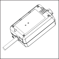
With the WeldCube Connector, all welding systems involved in production can be integrated into the Fronius WeldCube Premium documentation system, regardless of manufacturer.
If the power supply is lost, the WeldCube Connector stores the last data and ensures a safe shutdown process.
The WeldCube Connector is available in the following versions:
WeldCube Connector U/I
4,044,056
Measurement of welding current and welding voltage
incl. voltage measurement adapter
WeldCube Connector U/I/WFS WSM
4,044,057
Measurement of welding current, welding voltage, and wire speed
incl. wire sensor
(for the power sources TransSteel 3000c Pulse, TransSteel 3500c, and the wirefeeder VR 5000)
WeldCube Connector U/I/WFS Euro
4,044,058
Measurement of welding current, welding voltage, and wire speed
incl. Euro wire sensor
WeldCube Connector Advanced
4,044,067
Measurement of welding current, welding voltage, and wire speed
Wire sensor optional (see options from page (→))
Device concept
With the WeldCube Connector, all welding systems involved in production can be integrated into the Fronius WeldCube Premium documentation system, regardless of manufacturer.
If the power supply is lost, the WeldCube Connector stores the last data and ensures a safe shutdown process.
The WeldCube Connector is available in the following versions:
WeldCube Connector U/I
4,044,056
Measurement of welding current and welding voltage
incl. voltage measurement adapter
WeldCube Connector U/I/WFS WSM
4,044,057
Measurement of welding current, welding voltage, and wire speed
incl. wire sensor
(for the power sources TransSteel 3000c Pulse, TransSteel 3500c, and the wirefeeder VR 5000)
WeldCube Connector U/I/WFS Euro
4,044,058
Measurement of welding current, welding voltage, and wire speed
incl. Euro wire sensor
WeldCube Connector Advanced
4,044,067
Measurement of welding current, welding voltage, and wire speed
Wire sensor optional (see options from page (→))
Application areas
The WeldCube Connector is used in manual and automated MIG/MAG, TIG, and MMA applications.
Operating principle
Regardless of the welding process, the WeldCube Connector is always integrated between the power source and the grounding cable.
The current is measured at the current sockets of the power source.
For functional system integration, the following components must be connected:
- Connect the WeldCube Connector to the ground current socket of the power source
- Connect the grounding cable to the WeldCubeConnector
- Voltage measurement by adapter cable or voltage/wire speed measurement by wire sensor at the other pole
- Power supply via "Power over Ethernet" using a suitable network cable
- Connection to the network via LAN network cable or WLAN
The WeldCube Connector is powered via the network cable using Power over Ethernet (PoE).
The power supply via PoE can be provided by the central IT infrastructure or a PoE injector on site. The PoE injector is then integrated into the data line between the network distributor and the WeldCube Connector.
Safety symbols on the device
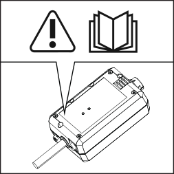

Welding is dangerous. The following basic requirements must be met:
- Adequate welding qualifications
- Appropriate protective equipment
- Exclusion of unauthorized persons

Do not use the functions described here until you have fully read and understood the following documents:
- These Operating Instructions
- All system component Operating Instructions, especially the safety rules
Requirements
NOTE!
Installing and integrating the WeldCube Connector requires an understanding of network technology.
For detailed information, consult your network administrator.
- RJ45 / M12 connection, X-coding
- Industrial cable version, min. CAT 5e
- Shielded RJ45 socket
- Robust and enclosed plastic housing
- Min. 100 Mbit/s data speed
- EMC device class: EN55032 Class B, FCC part 15 Class B
- Ambient temperature in operation: -10 °C to +40 °C
- Storage temperature: -20 °C to +55 °C
Options
PoE injector RJ45 30 W / 802.3at / PoE+ | 42,0411,0213 |
CE IEC power cable 2 m | 43,0004,2951 |
Network cable M12-X / RJ45, 5 m | 42,0411,0232 |
Network cable M12-X / RJ45, 10 m | 42,0411,0233 |
Network cable M12-X / RJ45, 15 m | 42,0411,0234 |
Network cable M12-X / RJ45, 20 m | 42,0411,0235 |
OPT/WCC Sensor Cable EXT 5m | 4,051,547 |
OPT/WCC Sensor Cable EXT 10m | 4,051,548 |
OPT/WCC Mounting Set TSt | 4,101,361 |
OPT/WCC Mounting Set 1  | 4,101,362 |
OPT/WCC Mounting Set 2  | 4,101,363 |
OPT/WCC Wire Sensor EUR | 4,101,372 |
OPT/WCC Wire Sensor WSM | 4,101,373 |
Holding magnet * | 4,100,265 |
|
|
| * | 2 holding magnets are required for the WeldCube Connector. |
FCC/RSS/EU compliance
FCC
This device conforms to the limits for a Class B digital device, pursuant to Part 15 of the FCC regulations. These limit values are designed to provide reasonable protection against harmful interference in a residential installation. This device generates and uses high frequency energy and, if not used in accordance with the instructions, may interfere with radio communications. However, there is no guarantee that interference will not occur in a particular installation.
If this device does cause harmful interference to radio or television reception, which can be determined by turning the device off and on again, the user is encouraged to try to correct the interference using one or more of the following measures:- Align or reposition the receiving antenna
- Increase the distance between the device and receiver.
- Connect the device to a different circuit than the receiver.
- Consult the dealer or an experienced radio/TV technician for help.
FCC ID: QKWSPB209A
Industry Canada RSS
This device complies with Industry Canada license-exempt RSS standards. Operation is subject to the following conditions:
| (1) | This device must not cause any harmful interference. |
| (2) | This device must not be affected by external sources of interference, including interference that may impair operation. |
IC: 12270A-SPB209A
EU
Compliance with directive 2014/53/EU - Radio Equipment Directive (RED)
The antennas used for this transmitter must be installed in such a way that a minimum distance of 20 cm from all persons is maintained. They must not be installed or operated in conjunction with another antenna or transmitter. OEM integrators and end users must ensure the operating conditions of the transmitter comply with radio frequency exposure guidelines.
Bluetooth trademarks
The word mark Bluetooth® and the Bluetooth® logos are registered trademarks and property of Bluetooth SIG, Inc. and are used by the manufacturer under license. Other trademarks and trade names are the property of their respective owners.
System configurations
System configurations with WeldCube Connector U/I
MIG/MAG
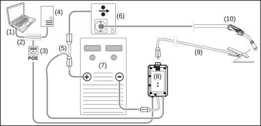
Schematic illustration, interconnecting hosepack not shown in detail between power source and wirefeeder
| (1) | Computer for access to WeldCube Premium |
| (2) | Ethernet switch with PoE |
| (3) | Power supply via PoE (Power over Ethernet) |
| (4) | WeldCube Premium Server (physical or VM) |
| (5) | Voltage measurement adapter |
| (6) | Wirefeeder |
| (7) | Power source |
| (8) | WeldCube Connector U/I |
| (9) | Grounding cable |
| (10) | Welding torch |
MIG/MAG with wire drive integrated in the power source
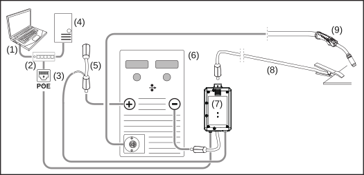
| (1) | Computer for access to WeldCube Premium |
| (2) | Ethernet switch with PoE |
| (3) | Power supply via PoE (Power over Ethernet) |
| (4) | WeldCube Premium Server (physical or VM) |
| (5) | Voltage measurement adapter |
| (6) | Power source |
| (7) | WeldCube Connector U/I |
| (8) | Grounding cable |
| (9) | Welding torch |
TIG-DC, TIG-AC
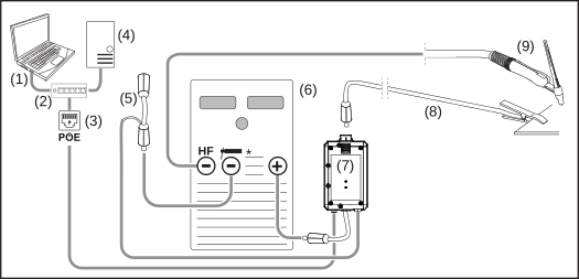
HF = high frequency ignition; * = high-frequency-free current socket - e.g., for rod electrodes
| (1) | Computer for access to WeldCube Premium |
| (2) | Ethernet switch with PoE |
| (3) | Power supply via PoE (Power over Ethernet) |
| (4) | WeldCube Premium Server (physical or VM) |
| (5) | Voltage measurement adapter |
| (6) | Power source |
| (7) | WeldCube Connector U/I |
| (8) | Grounding cable |
| (9) | Welding torch |
MMA (with TIG power source)
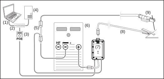
HF = high frequency ignition; * = high-frequency-free current socket - e.g., for rod electrodes
| (1) | Computer for access to WeldCube Premium |
| (2) | Ethernet switch with PoE |
| (3) | Power supply via PoE (Power over Ethernet) |
| (4) | WeldCube Premium Server (physical or VM) |
| (5) | Voltage measurement adapter |
| (6) | Power source |
| (7) | WeldCube Connector U/I |
| (8) | Grounding cable |
| (9) | Electrode holder |
System configurations with WeldCube Connector U/I
MIG/MAG
Schematic illustration, interconnecting hosepack not shown in detail between power source and wirefeeder
| (1) | Computer for access to WeldCube Premium |
| (2) | Ethernet switch with PoE |
| (3) | Power supply via PoE (Power over Ethernet) |
| (4) | WeldCube Premium Server (physical or VM) |
| (5) | Voltage measurement adapter |
| (6) | Wirefeeder |
| (7) | Power source |
| (8) | WeldCube Connector U/I |
| (9) | Grounding cable |
| (10) | Welding torch |
MIG/MAG with wire drive integrated in the power source
| (1) | Computer for access to WeldCube Premium |
| (2) | Ethernet switch with PoE |
| (3) | Power supply via PoE (Power over Ethernet) |
| (4) | WeldCube Premium Server (physical or VM) |
| (5) | Voltage measurement adapter |
| (6) | Power source |
| (7) | WeldCube Connector U/I |
| (8) | Grounding cable |
| (9) | Welding torch |
TIG-DC, TIG-AC
HF = high frequency ignition; * = high-frequency-free current socket - e.g., for rod electrodes
| (1) | Computer for access to WeldCube Premium |
| (2) | Ethernet switch with PoE |
| (3) | Power supply via PoE (Power over Ethernet) |
| (4) | WeldCube Premium Server (physical or VM) |
| (5) | Voltage measurement adapter |
| (6) | Power source |
| (7) | WeldCube Connector U/I |
| (8) | Grounding cable |
| (9) | Welding torch |
MMA (with TIG power source)
HF = high frequency ignition; * = high-frequency-free current socket - e.g., for rod electrodes
| (1) | Computer for access to WeldCube Premium |
| (2) | Ethernet switch with PoE |
| (3) | Power supply via PoE (Power over Ethernet) |
| (4) | WeldCube Premium Server (physical or VM) |
| (5) | Voltage measurement adapter |
| (6) | Power source |
| (7) | WeldCube Connector U/I |
| (8) | Grounding cable |
| (9) | Electrode holder |
System configurations with WeldCube Connector U/I/WFS Euro
MIG/MAG
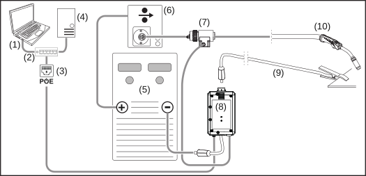
Schematic illustration, interconnecting hosepack not shown in detail between power source and wirefeeder
| (1) | Computer for access to WeldCube Premium |
| (2) | Ethernet switch with PoE |
| (3) | Power supply via PoE (Power over Ethernet) |
| (4) | WeldCube Premium Server (physical or VM) |
| (5) | Power source |
| (6) | Wirefeeder |
| (7) | Euro wire sensor |
| (8) | WeldCube Connector U/I |
| (9) | Return lead cable |
| (10) | Welding torch |
MIG/MAG with wire drive integrated in the power source
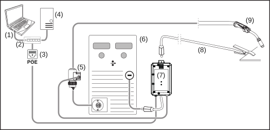
| (1) | Computer for access to WeldCube Premium |
| (2) | Ethernet switch with PoE |
| (3) | Power supply via PoE (Power over Ethernet) |
| (4) | WeldCube Premium Server (physical or VM) |
| (5) | Euro wire sensor |
| (6) | Power source |
| (7) | WeldCube Connector U/I |
| (8) | Return lead cable |
| (9) | Welding torch |
System configurations with WeldCube Connector U/I/WFS WSM
The system configuration for TransSteel welding systems with WeldCube Connector U/I/WFS WSM is the same as the system configuration for WeldCube Connector U/I/WFS Euro, except that instead of the Euro wire sensor, a wire sensor is integrated into the power source or wirefeeder itself.
The wire sensor is either installed at the factory or can be retrofitted by suitably trained and qualified personnel.
For details on installing the wire sensor, refer to the "WeldCube Connector wire sensor TransSteel" Installation Instructions - 42,0410,2663.
System configurations with WeldCube Connector Advanced
The system configuration for welding systems with WeldCube Connector Advanced is the same as the system configuration for WeldCube Connector U/I/WFS Euro.
Euro wire sensor or a wire sensor integrated into the TransSteel power sources are optionally available.
Operating controls, connections and mechanical components
Operating controls, connections, and mechanical components
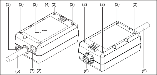
| (1) | M12 socket, X-coding For connecting a network cable |
| (2) | M5 threaded bushing 4 pieces per side For mounting the WeldCube Connector for the welding system 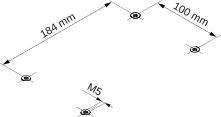 |
| (3) | Status LED Warnings, errors, and current operating states are output via the status LED |
| (4) | Power LED Information on the electrical supply to the WeldCube Connector is output via the Power LED The LEDs are described in the following section |
| (5) | Return lead cable with bayonet connector For connecting to the ground current socket of the power source NOTE!The ground connection on the power source depends on the welding process and does not necessarily have to coincide with the (-) current socket! |
| (6) | Ground current socket with bayonet latch For connecting the welding circuit return lead cable |
| (7) | Sensor connection Laboratory socket (for WeldCube Connector U/I) For connecting the voltage measurement adapter 19-pin sensor socket (for WeldCube Connector U/I/WFS WSM, WeldCube Connector U/I/WFS Euro, and WeldCube Connector Advanced) For connecting the wire sensor |
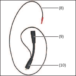
Voltage measurement adapter (only in conjunction with WeldCube Connector U/I)
| No. | Function |
|---|---|
| (8) | Measuring cable For connecting to the laboratory socket for WeldCube Connect U/I |
| (9) | (+) Current socket with bayonet latch For connecting the (+) welding circuit cable from the interconnecting hosepack |
| (10) | (+) cable with bayonet connector For connecting to the (+) current socket of the power source |
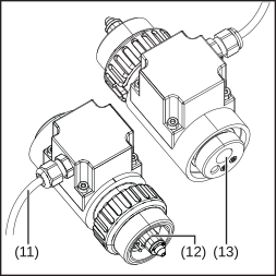
Euro wire sensor (only in conjunction with WeldCube Connector U/I/WFS Euro or as an option for WeldCube Connector Advanced)
| No. | Function |
|---|---|
| (11) | Measuring cable For connecting to the 19-pin sensor socket on WeldCube Connector U/I/WFS WSM, WeldCube Connector U/I/WFS Euro, and WeldCube Connector Advanced |
| (12) | Euro adapter For connecting to the power source |
| (13) | Euro torch connector For connecting the welding torch |
Operating controls, connections, and mechanical components
| (1) | M12 socket, X-coding For connecting a network cable |
| (2) | M5 threaded bushing 4 pieces per side For mounting the WeldCube Connector for the welding system |
| (3) | Status LED Warnings, errors, and current operating states are output via the status LED |
| (4) | Power LED Information on the electrical supply to the WeldCube Connector is output via the Power LED The LEDs are described in the following section |
| (5) | Return lead cable with bayonet connector For connecting to the ground current socket of the power source NOTE!The ground connection on the power source depends on the welding process and does not necessarily have to coincide with the (-) current socket! |
| (6) | Ground current socket with bayonet latch For connecting the welding circuit return lead cable |
| (7) | Sensor connection Laboratory socket (for WeldCube Connector U/I) For connecting the voltage measurement adapter 19-pin sensor socket (for WeldCube Connector U/I/WFS WSM, WeldCube Connector U/I/WFS Euro, and WeldCube Connector Advanced) For connecting the wire sensor |
Voltage measurement adapter (only in conjunction with WeldCube Connector U/I)
| No. | Function |
|---|---|
| (8) | Measuring cable For connecting to the laboratory socket for WeldCube Connect U/I |
| (9) | (+) Current socket with bayonet latch For connecting the (+) welding circuit cable from the interconnecting hosepack |
| (10) | (+) cable with bayonet connector For connecting to the (+) current socket of the power source |
Euro wire sensor (only in conjunction with WeldCube Connector U/I/WFS Euro or as an option for WeldCube Connector Advanced)
| No. | Function |
|---|---|
| (11) | Measuring cable For connecting to the 19-pin sensor socket on WeldCube Connector U/I/WFS WSM, WeldCube Connector U/I/WFS Euro, and WeldCube Connector Advanced |
| (12) | Euro adapter For connecting to the power source |
| (13) | Euro torch connector For connecting the welding torch |
Power LED, status LED
Power LED
lights up green:
electrical supply available
lights up orange:
no electrical supply available - power is currently being supplied internally, until all data is saved
does not light up:
no electrical supply available
Status LED
When the electrical supply is on, the status LED may light up or flash in the following colors:
lights up green:
device ready for operation, everything OK
flashes green (at 5 Hz):
initial connection established between WeldConnect app and WeldCube Connector, e.g., for commissioning or configuration purposes
lights up orange:
warning
flashes orange (at 0.5 Hz):
device not yet in operation
lights up red:
error
a pending error can be checked in the SmartManager or WeldCube Premium logbook.
flashes in the current color (at 2.5 Hz):
welding detected
Connection Options
Connection Options
- via LAN
- via WLAN
Connection Options
- via LAN
- via WLAN
Connection via LAN
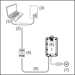
| (1) | Computer for access to WeldCube Premium |
| (2) | Ethernet switch with PoE |
| (3) | WeldCube Premium Server |
| (4) | Power supply via PoE (Power over Ethernet) |
| (5) | Network cable |
| (6) | WeldCube Connector |
| (7) | Ground connection on the power source |
NOTE!
The ground connection on the power source depends on the welding process and does not necessarily have to coincide with the (-) current socket!
Connection via WLAN
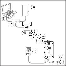
| (1) | Computer for access to WeldCube Premium |
| (2) | Ethernet switch |
| (3) | WeldCube Premium Server |
| (4) | WLAN AccessPoint |
| (5) | Power supply via PoE (Power over Ethernet) |
| (6) | WeldCube Connector |
| (7) | Ground connection on the power source |
NOTE!
The ground connection on the power source depends on the welding process and does not necessarily have to coincide with the (-) current socket!
Instructions for installation and operation
Installation information
- The WeldCube Connector must be attached to the power source or a component of the welding system, e.g., the trolley.
- The WeldCube Connector must not lie on the ground.
- The WeldCube Connector can be mounted in any position.
- Max. length between 2 active network components (e.g., between WeldCube Connector and Ethernet switch with PoE): 90 m
- Position the WeldCube Connector so that the LEDs are clearly visible.
- Do not position the WeldCube Connector in the area of hot exhaust air from the power source or in the area of heated system components.
- Position the WeldCube Connector such that it is protected from welding spatter.
- Use an adequately dimensioned grounding cable.
- Secure the network cable, sensor cable and measuring cable to the grounding cable of the WeldCube Connector using cable ties (strain relief)
Installation information
- The WeldCube Connector must be attached to the power source or a component of the welding system, e.g., the trolley.
- The WeldCube Connector must not lie on the ground.
- The WeldCube Connector can be mounted in any position.
- Max. length between 2 active network components (e.g., between WeldCube Connector and Ethernet switch with PoE): 90 m
- Position the WeldCube Connector so that the LEDs are clearly visible.
- Do not position the WeldCube Connector in the area of hot exhaust air from the power source or in the area of heated system components.
- Position the WeldCube Connector such that it is protected from welding spatter.
- Use an adequately dimensioned grounding cable.
- Secure the network cable, sensor cable and measuring cable to the grounding cable of the WeldCube Connector using cable ties (strain relief)
Operating Instructions
NOTE!
The WeldCube Connector suppresses HF high voltage pulses!
If a TIG welding process with integrated WeldCube Connector needs to be ignited by means of HF high-voltage pulses, HF ignition will not take place.
If available, only connect cable to an HF-free current socket (e.g. for manual metal arc welding).
If an HF-free current socket is not available, deactivate HF ignition.
HF = high frequency
Before each use of the WeldCube Connector:- Check all welding and measuring cables for damage.
- Check connecting plugs are correctly and firmly connected.
- Check LEDs
- Visually inspect the housing and plug
NOTE!
When measuring TIG-AC welds, an arithmetically rectified value is documented.
Fronius Data Channel
Part designation, part serial number and weld seam number can be sent to the WeldCube Connector via the Fronius Data Channel.
The Fronius Data Channel is a TCP / IP server that runs on the WeldCube Connector administration port. This port is used for documentation and communication as well as servicing purposes and this interface is monitored on TCP port 4714.
A PC program or a higher-level controller establishes a TCP socket connection to the IP address of the WeldCube Connector at TCP port 4714. The parameters are transmitted as key or set value text lists separated by semicolons.
The following parameters are supported:
| No. | Parameter |
|---|---|
| 1 | Process active During an active welding process (from gas pre-flow at the start of welding to gas post-flow at the end of welding), the WeldCube Connector outputs the process active signal = 1 to the controller. |
| 2 | Current flow When the current flow is active during welding, the WeldCube Connector outputs the current flow signal = 1 to the controller. |
| 3 | Part item number The controller gives the WeldCube Connector the item number of the part being welded using ASCII characters A-Z, a-z and 0-9. |
| 4 | Part serial number The controller gives the WeldCube Connector the serial number of the part being welded using ASCII characters A-Z, a-z and 0-9. |
| 5 | Seam number The controller gives the WeldCube Connector the seam being welded (welding position) using ASCII characters 0-9. |
Data transfer via the Fronius Data Channel can be tested using the following programs:
- Windows® PuTTy
- Linux Socat
A TCP socket connection must first be established for the data transfer.
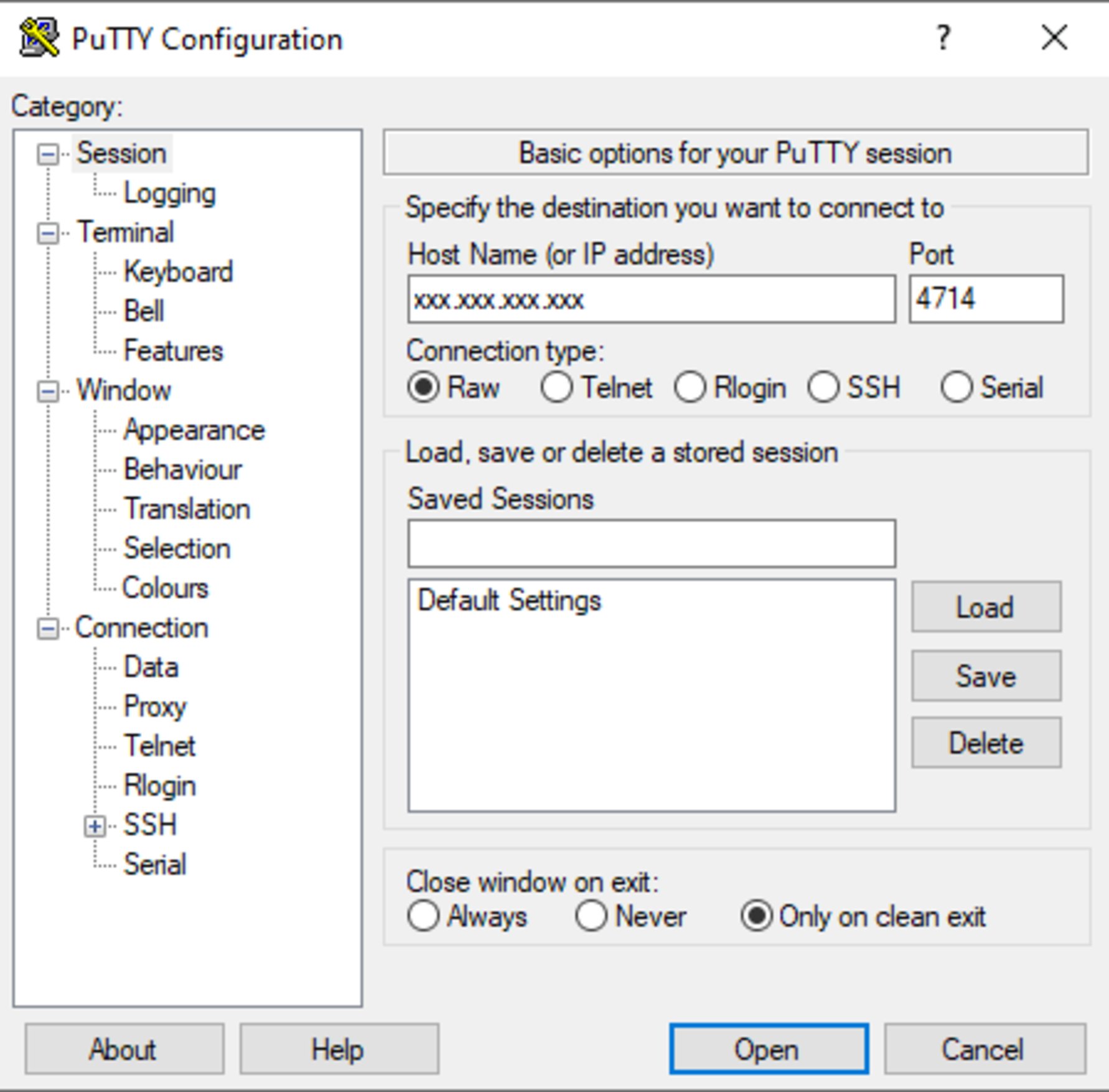
Example Windows® PuTTY
1Enter the IP address of the service port of the WeldCube Connector and the port number 4714
Commissioning
Safety
WARNING!
Danger from incorrect operation and work that is not carried out properly.
This can result in serious personal injury and damage to property.
All the work and functions described in this document must only be carried out by technically trained and qualified personnel.
Read and understand this document in full.
Read and understand all safety rules and user documentation for this equipment and all system components.
Safety
WARNING!
Danger from incorrect operation and work that is not carried out properly.
This can result in serious personal injury and damage to property.
All the work and functions described in this document must only be carried out by technically trained and qualified personnel.
Read and understand this document in full.
Read and understand all safety rules and user documentation for this equipment and all system components.
Requirements
NOTE!
Installing and integrating the WeldCube Connector requires an understanding of network technology.
For detailed information, consult your network administrator.
- The WeldCube Connector must be integrated into the welding system according to one of the system configurations.
- Available PoE power supply
- Fronius WeldConnect app installed on the smartphone
- Bluetooth activated on the smartphone
Commissioning
The WeldCube Connector is commissioned using a smartphone and the Fronius WeldConnect app.
NOTE!
If the power source has a function for determining the welding circuit resistance R, determine the welding circuit resistance of the welding system before commissioning using the WeldCube Connector that is in place.
The welding circuit resistance value must be correct to get accurate measurement results!
Enter the welding circuit resistance value found using the Installation Wizard at Setup 5/6.
If there is no function for determining the welding circuit resistance on the power source, use the calculation tool in the Installation Wizard at Setup 5/6.
1Determine the welding circuit resistance of the welding system incl. WeldCube Connector
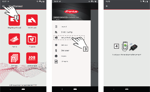
2Start the WeldConnect app and open the menu
3Select Setup WeldCube Connector
4Bring smartphone into the immediate vicinity of the WeldCube Connector
A successfully started connection is indicated on the WeldCube Connector:
the status LED flashes green 5 times per second
A successfully started connection is indicated on the WeldCube Connector:
the status LED flashes green 5 times per second
5Follow the instructions in the Installation Wizard:
Setup 1/7
Enter name, site, hall, cell, and additional information
Setup 2/7
Enter network data
Setup 3/7
Enter WLAN data
Setup 4/7
Enter date, time, and time zone
Setup 5/7
Enter the welding circuit resistance determined in step 1
or
Start the calculation tool
Setup 6/7
Enter ignition hidden time and the sample rate for the documentation
Setup 7/7
Optionally enter wire diameter and filler metal
If wire diameter and filler metal are entered, they are also logged in WeldCube Premium.
Setup 1/7
Enter name, site, hall, cell, and additional information
Setup 2/7
Enter network data
Setup 3/7
Enter WLAN data
Setup 4/7
Enter date, time, and time zone
Setup 5/7
Enter the welding circuit resistance determined in step 1
or
Start the calculation tool
Setup 6/7
Enter ignition hidden time and the sample rate for the documentation
Setup 7/7
Optionally enter wire diameter and filler metal
If wire diameter and filler metal are entered, they are also logged in WeldCube Premium.
6Complete WeldCube Connector setup
The documented data can now be viewed in the SmartManager or analyzed with WeldCube Premium.
The documented data can now be viewed in the SmartManager or analyzed with WeldCube Premium.
For data analysis with WeldCube Premium:
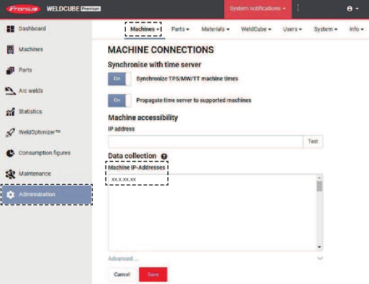
7Enter the IP address of the WeldCube Connector under Administration / Machines / Machine IP-Addresses
The recorded welding operations are then available in the Fronius WeldCube Premium documentation system under Machines / WeldCube Connector.
SmartManager - the website of the WeldCube Connector
General
With the SmartManager, the WeldCube Connector has its own website.
Once the WeldCube Connector is connected to a computer via a network cable or WLAN or is integrated into a network, the SmartManager of the WeldCube Connector can be accessed via the IP address.
IE 10 or higher or another modern browser is required in order to access the SmartManager.
The following entries are available for the WeldCube Connector:
|
|
General
With the SmartManager, the WeldCube Connector has its own website.
Once the WeldCube Connector is connected to a computer via a network cable or WLAN or is integrated into a network, the SmartManager of the WeldCube Connector can be accessed via the IP address.
IE 10 or higher or another modern browser is required in order to access the SmartManager.
The following entries are available for the WeldCube Connector:
|
|
Starting and logging into SmartManager
1Enter the IP address of the WeldCube Connector into the search field of the browser
2Enter user name and password
Factory setting:
User name = admin
Password = admin
Factory setting:
User name = admin
Password = admin
3Confirm the displayed message
The SmartManager of the WeldCube Connector is displayed.
Unlock function if logging in does not work
When logging into the SmartManager, the unlock function can be used to unlock a WeldCube Connector that was unintentionally locked and enable it for all functions.
1Click on "Start unlock function?"
2Create a verification file:
click on "Store"
click on "Store"
A .txt file with the following file name is saved in the computer's download folder:
unlock_SN[serial number]_YYYY_MM_DD_hhmmss.txt
3Send this verification file via e-mail to Fronius Technical Support at:
welding.techsupport@fronius.com
welding.techsupport@fronius.com
Fronius will reply by e-mail with a one-time unlock file with the following file name:
response_SN[serial number]_YYYY_MM_DD_hhmmss.txt
4Save the unlock file to the computer
5Click on "Find unlock file"
6Save the unlock file
7Click on "Load unlock file"
The Admin password of the WeldCube Connector is reset once to factory settings.
Changing the password/logging out

Click on this symbol to
- change the user password
- log out of the SmartManager
Changing the password for the SmartManager:
1Enter the old password
2Enter a new password
3Repeat the new password
4Click on "Store"
Settings

By clicking on this symbol, the units and standards for the WeldCube Connector can be set.
The settings depend on the user who is logged in.
Selecting the language

Click on the language abbreviation to display the languages available for the SmartManager.
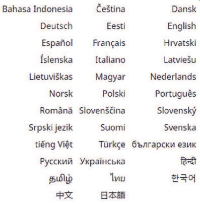
To change the language, click on the desired language.
Status display
The current status of the WeldCube Connector is displayed between the Fronius logo and the displayed WeldCube Connector.
 Caution/warning |  Error on the WeldCube Connector * |
 Welding in progress |  WeldCube Connector is ready for operation (online) |
 WeldCube Connector is not ready for operation (offline) |
|
| * | In the event of an error, a red error line with the error number appears above the line with the Fronius logo. After clicking on the error line, an error description is displayed. |
Fronius

Click on the Fronius logo to open the Fronius homepage: www.fronius.com
Current system data
Current system data
Any current WeldCube Connector data is displayed:
Machine name | Hall Cell | Additional information |
ACTUAL | ||
| ||
Welding current | Welding voltage | Wire speed * |
Current arc power | ||
Current arc energy | ||
| ||
Arc time | Total operating hours | |
* Only for WeldCube Connector U/I/WFS WSM and WeldCube Connector U/I/WFS Euro
Current system data
Any current WeldCube Connector data is displayed:
Machine name | Hall Cell | Additional information |
ACTUAL | ||
| ||
Welding current | Welding voltage | Wire speed * |
Current arc power | ||
Current arc energy | ||
| ||
Arc time | Total operating hours | |
* Only for WeldCube Connector U/I/WFS WSM and WeldCube Connector U/I/WFS Euro
Documentation logbook
Documentation logbook
The Documentation logbook entry shows the last 100 logbook entries. These logbook entries can be welds, errors, warnings, notifications and events.
The "Time filter" button can be used to filter the displayed data by a specific time period. This is entered with date (yyyy MM dd) and time (hh mm), each from - to.
An empty filter reloads the most recent welding operations.
The display of welding operations, errors, and events can be deactivated.
The following data is displayed:

| (1) | Log type |
| (2) | Seam number |
| (3) | Part item number |
| (4) | Part serial number |
| (5) | Start time (local time) |
| (6) | Welding duration |
| (7) | Welding current in A (rectified average) |
| (8) | Welding voltage in V (rectified average) |
| (9) | Wire speed in m/min * |
| (10) | IP - arc power in W (based on real-time values according to ISO/TR 18491) |
| (11) | IE - arc energy in kJ (as the total throughout the entire welding process according to ISO/TR 18491) |
| (12) | reserved for other data |
| * | Only for WeldCube Connector U/I/WFS WSM and WeldCube Connector U/I/WFS Euro |

Additional values can be also displayed by clicking on the "Insert column" button:
- I max / I min: maximum/minimum welding current in A
- Power max / Power min: maximum/minimum arc power in W
- Start time (power source time); date and time
- U max / U min: maximum/minimum welding voltage in V
- Vd max / Vd min: maximum / minimum wire speed in m/min
Documentation logbook
The Documentation logbook entry shows the last 100 logbook entries. These logbook entries can be welds, errors, warnings, notifications and events.
The "Time filter" button can be used to filter the displayed data by a specific time period. This is entered with date (yyyy MM dd) and time (hh mm), each from - to.
An empty filter reloads the most recent welding operations.
The display of welding operations, errors, and events can be deactivated.
The following data is displayed:
| (1) | Log type |
| (2) | Seam number |
| (3) | Part item number |
| (4) | Part serial number |
| (5) | Start time (local time) |
| (6) | Welding duration |
| (7) | Welding current in A (rectified average) |
| (8) | Welding voltage in V (rectified average) |
| (9) | Wire speed in m/min * |
| (10) | IP - arc power in W (based on real-time values according to ISO/TR 18491) |
| (11) | IE - arc energy in kJ (as the total throughout the entire welding process according to ISO/TR 18491) |
| (12) | reserved for other data |
| * | Only for WeldCube Connector U/I/WFS WSM and WeldCube Connector U/I/WFS Euro |
Additional values can be also displayed by clicking on the "Insert column" button:
- I max / I min: maximum/minimum welding current in A
- Power max / Power min: maximum/minimum arc power in W
- Start time (power source time); date and time
- U max / U min: maximum/minimum welding voltage in V
- Vd max / Vd min: maximum / minimum wire speed in m/min
Basic settings
In the Documentation logbook entry, the sampling rate for the documentation and rules for hiding the ignition phase can be set under Basic settings.
Sampling rate
0.1 - 100 s / off
Factory setting: 0.1 s
0.1 - 100.0 s
Documentation is saved at the set sampling rate.
off
Sampling rate is deactivated, only average values are stored.
Hide ignition phase
Period of time for which the ignition phase of the weld is to be hidden
(e.g. in order to prevent the ignition phase from affecting the measurement results in the case of short welds)
0.1 - 2 s / off
0.1 - 2 s
The welding data is not documented until the set time value has elapsed.
off
The ignition phase is documented at the same time.
Device Options
Default settings
The welding circuit resistance can be adjusted under the default settings.
The currently set resistance is displayed.
To calculate the resistance:
1Click on the Start calculation aid button
2Enter the length and cross section of the hosepack
3Enter the grounding cable length and cross-section
4Enter the number of separable connections
The calculated resistance value is displayed immediately.
The calculated resistance value is displayed immediately.
5Click on the Yes button to accept the calculated resistance
6Finally, save or discard the changes
Default settings
The welding circuit resistance can be adjusted under the default settings.
The currently set resistance is displayed.
To calculate the resistance:
1Click on the Start calculation aid button
2Enter the length and cross section of the hosepack
3Enter the grounding cable length and cross-section
4Enter the number of separable connections
The calculated resistance value is displayed immediately.
The calculated resistance value is displayed immediately.
5Click on the Yes button to accept the calculated resistance
6Finally, save or discard the changes
Designation & location
The power source configuration can be viewed and modified under Designation & location.
Date and time
Under Date and Time, the time zone, date, and time can be set.
The setting can be made manually or automatically.
Network settings
Under Network settings, the data for integrating the WeldCube Connector into a network can be entered:
Management- MAC address is displayed
- Current IP address is displayed
- DHCP can be enabled or disabled
With DHCP deactivated, the following data can be entered:
- IP address
- Network mask
- Default gateway
- DNS server 1
- DNS server 2
The following data can be entered with an active WLAN connection:
- MAC address
- Current IP address
Save and restore
Save and restore
Starting a backup
1Click on "Start backup" to save the WeldCube Connector data as a backup
By default, the data is saved in the format MCU1-YYYYMMDTHHmm.fbc in the selected location.
YYYY = year
MM = month
DD = day
HH = hour
mm = minute
The following data is saved in the backup:
By default, the data is saved in the format MCU1-YYYYMMDTHHmm.fbc in the selected location.
YYYY = year
MM = month
DD = day
HH = hour
mm = minute
The following data is saved in the backup:
- the documentation sampling rate
- machine name and installation site
- time and date
Finding a recovery file
1Click on "Find recovery file" to transfer an existing backup to the power source
2Select the file and click on "Open"
The selected backup file appears in the SmartManager for the power source under Restore.
The selected backup file appears in the SmartManager for the power source under Restore.
3Click on "Start restore"
Once the data has been successfully restored, a confirmation is displayed.
Once the data has been successfully restored, a confirmation is displayed.
Save and restore
Starting a backup
1Click on "Start backup" to save the WeldCube Connector data as a backup
By default, the data is saved in the format MCU1-YYYYMMDTHHmm.fbc in the selected location.
YYYY = year
MM = month
DD = day
HH = hour
mm = minute
The following data is saved in the backup:
By default, the data is saved in the format MCU1-YYYYMMDTHHmm.fbc in the selected location.
YYYY = year
MM = month
DD = day
HH = hour
mm = minute
The following data is saved in the backup:
- the documentation sampling rate
- machine name and installation site
- time and date
Finding a recovery file
1Click on "Find recovery file" to transfer an existing backup to the power source
2Select the file and click on "Open"
The selected backup file appears in the SmartManager for the power source under Restore.
The selected backup file appears in the SmartManager for the power source under Restore.
3Click on "Start restore"
Once the data has been successfully restored, a confirmation is displayed.
Once the data has been successfully restored, a confirmation is displayed.
Automatic backup
1Enable interval settings
2Enter the interval settings for the times at which the automatic backup should take place:
- Interval:
daily/weekly/monthly - at:
time (hh:mm)
3Enter the data for the backup destination:
- Protocol:
SFTP (Secure File Transfer Protocol) / SMB (Server Message Block) - Server:
Enter the IP address of the destination server - Port:
Enter port number; if no port number is entered, the standard port 22 is automatically used.
If SMB is set under Protocol, leave the Port field blank. - Storage location:
Used to configure the subfolder where the backup will be stored.
If no location is entered, the backup is stored in the server root directory.
IMPORTANT! For SMB and SFTB, always enter the location with a slash "/". - Domain/user, password:
User name and password - as configured on the server;
When entering a domain, first enter the domain, then backslash "\" and then the user name (DOMAIN\USER)
4If a connection via proxy server is required, activate and enter the proxy settings:
- Server
- Port
- User
- Password
5Save changes
6Activate automatic backup
If you have any questions about configuration, contact your network administrator.
User management
General
Under the User administration entry
- Users can be viewed, changed, and created.
- User roles can be viewed, changed, and created.
- Users and user roles can be exported or imported into the WeldCube Connector.
During import, existing user management data on the WeldCube Connector is overwritten. - A CENTRUM server can be activated.
User management is created on one WeldCube Connector and can then be saved with the export/import function and transferred to other WeldCube Connectors.
General
Under the User administration entry
- Users can be viewed, changed, and created.
- User roles can be viewed, changed, and created.
- Users and user roles can be exported or imported into the WeldCube Connector.
During import, existing user management data on the WeldCube Connector is overwritten. - A CENTRUM server can be activated.
User management is created on one WeldCube Connector and can then be saved with the export/import function and transferred to other WeldCube Connectors.
Users
Existing users can be viewed, changed and deleted, new users can be created.
Viewing/changing a user:
1Select a user
2Change user data directly in the display field
3Save the changes
Deleting a user:
1Select a user
2Click on the "Delete user" button
3Confirm the prompt with "OK"
Creating a user:
1Click on the "Create new user" button
2Enter user data
3Confirm with OK
User roles
Existing user roles can be viewed, changed and deleted, new user roles can be created.
Viewing/changing a user role:
1Select a user role
2Change user role data directly in the display field
3Save the changes
The "Administrator" role cannot be changed.
Deleting a user role:
1Select a user role
2Click on the "Delete user role" button
3Confirm the prompt with "OK"
The "Administrator" and "locked" roles cannot be deleted.
Creating a user role:
1Click on the "Create new user role" button
2Enter a role name, apply values
3Confirm with OK
Export & import
Exporting users and user roles from a WeldCube Connector
1Click on "export"
User management for the WeldCube Connector is stored in the computer's download folder.
File format: userbackup_SNxxxxxxxx_YYYY_MM_DD_hhmmss.user
SN = serial number, YYYY = year, MM = month, DD = day
hh = hour, mm = minute, ss = second
Importing users and user roles into a WeldCube Connector
1Click on "Find user data file"
2Select the file and click on "open"
3Click on "import"
User management is stored on the WeldCube Connector.
CENTRUM
To activate a CENTRUM server
(CENTRUM = Central User Management)
1Activate CENTRUM Server
2In the input field, enter the domain name or IP address of the server on which Central User Management has been installed.
If a domain name is used, a valid DNS server must be configured under the WeldCube Connector network settings.
If a domain name is used, a valid DNS server must be configured under the WeldCube Connector network settings.
3Click on the "Verify server" button
The availability of the specified server is checked.
The availability of the specified server is checked.
4Save the changes
Overview
Overview
The Overview entry displays the components of the WeldCube Connector with all the available information, e.g., firmware version, item number, serial number, production date, etc.
Overview
The Overview entry displays the components of the WeldCube Connector with all the available information, e.g., firmware version, item number, serial number, production date, etc.
Expanding all groups/collapsing all groups
Click on the "Expand all groups" button to see further details about the individual components.
Example SCU1:
- Item number
- RD SCU1
Item number, serial number, production date
Bootloader: version
Image version - Licenses
Click on the "Collapse all groups" button to hide the details of the system components.
Export component overview as ...
Click on the "Export component overview as" button to create an XML file from the details of the system components. This XML file can either be opened or saved.
Update
Update
Under the Update entry, the firmware of the WeldCube Connector can be updated.
The current firmware version is displayed.
To update the firmware of the WeldCube Connector:
1Organize and save the update file
2Click on "Find update file" to start the update process
3Select the update fileClick on "Update"
After the update has been successfully completed, a confirmation message is displayed.
Update
Under the Update entry, the firmware of the WeldCube Connector can be updated.
The current firmware version is displayed.
To update the firmware of the WeldCube Connector:
1Organize and save the update file
2Click on "Find update file" to start the update process
3Select the update fileClick on "Update"
After the update has been successfully completed, a confirmation message is displayed.
Finding the update file (performing an update)
1After clicking on "Find update file", select the desired firmware (*.ffw)
2Click on "Open"
The selected update file appears in the SmartManager under Update.
The selected update file appears in the SmartManager under Update.
3Click on "Update"
The progress of the update process is displayed.
Once this reaches 100%, the prompt to restart the power source appears.
The progress of the update process is displayed.
Once this reaches 100%, the prompt to restart the power source appears.

The SmartManager is not available during the restart.
After the restart, the SmartManager may no longer be available.
If you select No, the new software functions will be activated the next time the power is turned on/off.
After a successful update, a confirmation and the current firmware version is displayed.
Then log into the SmartManager again.
Fronius WeldConnect
 | Under the Update entry, the Fronius WeldConnect mobile application can also be called up. |
WeldConnect can be used to perform the following functions:
- Current device configuration at a glance
- Mobile access to the SmartManager of the power source
- Automatic determination of output parameters for MIG/MAG and TIG
- Cloud storage and wireless transmission to the power source
- Component identification
- Log on and off the power source without NFC card
- Save and share parameters and jobs
- Data transfer from one power source to another by means of backup, restore
- Firmware update
Fronius WeldConnect is available as follows:
- As an app for Android
- As an app for Apple/IOS
For more information on Fronius WeldConnect, visit:

https://www.fronius.com/en/welding-technology/innovative-solutions/weldconnect
Troubleshooting
Error display
An error is indicated by a red lit or red flashing status LED on the WeldCube Connector.
The error can be checked in the SmartManager or WeldCube Premium logbook.
Error display
An error is indicated by a red lit or red flashing status LED on the WeldCube Connector.
The error can be checked in the SmartManager or WeldCube Premium logbook.
Troubleshooting
4
Sensor PC board could not be found
| Cause: | Connection error to the sensor PC board |
| Remedy: | Contact the Fronius service team |
53
WeldCube Connector backup power supply not available
| Cause: | The backup supply is defective. |
| Remedy: | Contact the Fronius service team |
NOTE!If the backup supply is not available, a disconnection of the electrical supply may result the recorded welding data of the last 24 hours being lost! A permanent connection of the WeldCube Connector to WeldCube Premium can reduce the loss of recorded welding data in the event of a fault. | |
56
Operating temperature of the WeldCube Connector is outside the permissible range
| Cause: | Internal temperature of the WeldCube Connector is too low or too high |
| Remedy: | Change the position of the WeldCube Connector |
| Cause: | Poor contact due to oxidized or damaged contact surfaces on the power plugs |
| Remedy: | Clean or replace power plugs |
57
Time and date are not set
| Cause: | Time and date are not set |
| Remedy: | Set the time and date (e.g. in the SmartManager or using the Fronius WeldConnect app.) |
Service, maintenance and disposal
Safety
WARNING!
Danger from incorrect operation and work that is not carried out properly.
This can result in serious personal injury and damage to property.
All the work and functions described in this document must only be carried out by technically trained and qualified personnel.
Read and understand this document in full.
Read and understand all safety rules and user documentation for this equipment and all system components.
WARNING!
Danger from electrical current.
This can result in serious personal injury and damage to property.
Before starting work, switch off all devices and components involved, and disconnect them from the grid.
Secure all devices and components involved so they cannot be switched back on.
After opening the device, use a suitable measuring instrument to check that electrically charged components (such as capacitors) have been discharged.
WARNING!
Danger due to insufficient ground conductor connection.
This can result in serious personal injury and damage to property.
The housing screws provide a suitable ground conductor connection for grounding the housing.
The housing screws must not under any circumstances be replaced by other screws without a reliable ground conductor connection.
Safety
WARNING!
Danger from incorrect operation and work that is not carried out properly.
This can result in serious personal injury and damage to property.
All the work and functions described in this document must only be carried out by technically trained and qualified personnel.
Read and understand this document in full.
Read and understand all safety rules and user documentation for this equipment and all system components.
WARNING!
Danger from electrical current.
This can result in serious personal injury and damage to property.
Before starting work, switch off all devices and components involved, and disconnect them from the grid.
Secure all devices and components involved so they cannot be switched back on.
After opening the device, use a suitable measuring instrument to check that electrically charged components (such as capacitors) have been discharged.
WARNING!
Danger due to insufficient ground conductor connection.
This can result in serious personal injury and damage to property.
The housing screws provide a suitable ground conductor connection for grounding the housing.
The housing screws must not under any circumstances be replaced by other screws without a reliable ground conductor connection.
Monthly maintenance activities
Check Euro wire sensor or wire sensor installed in TransSteel/VR 5000 monthly; if necessary, clean with compressed air up to max. 5 bar
Calibration
The WeldCube Connector should be calibrated once a year by Fronius according to IEC 60974-14.
Disposal
Materials should be disposed of according to valid local and national regulations.
Technical data
WeldCube Connector
Welding current measuring range |
|
Duty cycle Continuous current Pulse current |
500 A / 60 % ED max. 700 A |
Welding voltage measurement range | 0 - 141 V |
Measurement frequency * | 10 kHz |
Threshold values for recording welding data | > 8 A / > 100 ms ** |
Electrical power supply | PoE+ / 30 W |
Protection class | IP 44 |
Insulation class | B |
EMC device class | B |
Housing dimensions L x W x H | 225 x 140 x 90 mm |
Grounding cable length (housing - outer edge of bayonet connector, without pin) | 125 cm |
Weight | 3 kg |
Mark of conformity | CE, CSA |
|
|
| * | Measurements are logged as average values at the set sampling rate. To set the sampling rate, see page (→). |
| ** | The total welding time should be > 100 ms. |
| *** | Arc breaks are not detected by the WeldCube Connector. An arc break > 0.5 s is regarded as a separate weld. |
| ED | = Duty cycle |
WeldCube Connector
Welding current measuring range |
|
Duty cycle Continuous current Pulse current |
500 A / 60 % ED max. 700 A |
Welding voltage measurement range | 0 - 141 V |
Measurement frequency * | 10 kHz |
Threshold values for recording welding data | > 8 A / > 100 ms ** |
Electrical power supply | PoE+ / 30 W |
Protection class | IP 44 |
Insulation class | B |
EMC device class | B |
Housing dimensions L x W x H | 225 x 140 x 90 mm |
Grounding cable length (housing - outer edge of bayonet connector, without pin) | 125 cm |
Weight | 3 kg |
Mark of conformity | CE, CSA |
|
|
| * | Measurements are logged as average values at the set sampling rate. To set the sampling rate, see page (→). |
| ** | The total welding time should be > 100 ms. |
| *** | Arc breaks are not detected by the WeldCube Connector. An arc break > 0.5 s is regarded as a separate weld. |
| ED | = Duty cycle |
Wire sensor
Wire diameter | 0.8 - 2.0 mm |
Wire speed | max. 30 m/min |
Duty cycle | 500 A / 60 % ED |
Measuring cable length | 2 m |
|
|
| ED | = Duty cycle |