Safety rules
Safety rules
Explanation of safety notices
DANGER!
Indicates immediate danger.
If not avoided, death or serious injury will result.
WARNING!
Indicates a potentially hazardous situation.
If not avoided, death or serious injury may result.
CAUTION!
Indicates a situation where damage or injury could occur.
If not avoided, minor injury and/or damage to property may result.
NOTE!
Indicates a risk of flawed results and possible damage to the equipment.
General
- Injury or death to the operator or a third party
- Damage to the device and other material assets belonging to the operating company.
- Be suitably qualified
- Have knowledge of and experience in dealing with electrical installations and
- Have fully read and precisely followed these Operating Instructions
The Operating Instructions must always be at hand wherever the device is being used. In addition to the Operating Instructions, attention must also be paid to any generally applicable and local regulations regarding accident prevention and environmental protection.
All safety and danger notices on the device:- Must be kept in a legible state
- Must not be damaged
- Must not be removed
- Must not be covered, pasted or painted over
The terminals can reach high temperatures.
Only operate the device when all protection devices are fully functional. If the protection devices are not fully functional, there is a danger of:- Injury or death to the operator or a third party
- Damage to the device and other material assets belonging to the operating company
Any safety devices that are not fully functional must be repaired by an authorised specialist before the device is switched on.
Never bypass or disable protection devices.
For the location of the safety and danger notices on the device, refer to the section headed "General remarks" in the Operating Instructions for the device.
Any equipment malfunctions which might impair safety must be remedied before the device is turned on.
This is for your personal safety!
Environmental conditions
Operation or storage of the device outside the stipulated area will be deemed as not in accordance with the intended purpose. The manufacturer accepts no liability for any damage resulting from improper use.
Qualified personnel
The servicing information contained in these operating instructions is intended only for the use of qualified service engineers. An electric shock can be fatal. Do not carry out any actions other than those described in the documentation. This also applies to qualified personnel.
All cables and leads must be secured, undamaged, insulated and adequately dimensioned. Loose connections, scorched, damaged or inadequately dimensioned cables and leads must be immediately repaired by authorised personnel.
Maintenance and repair work must only be carried out by an authorised specialist.
It is impossible to guarantee that bought-in parts are designed and manufactured to meet the demands made on them, or that they satisfy safety requirements. Use only original spare parts (also applies to standard parts).
Do not carry out any alterations, installations, or modifications to the device without first obtaining the manufacturer's permission.
Components that are not in perfect condition must be changed immediately.
Noise emission values
The maximum sound power level of the inverter is specified in the Technical Data.
The device is cooled as quietly as possible with the aid of an electronic temperature control system; this depends on the amount of converted power, the ambient temperature, the level of soiling of the device, etc.
It is not possible to provide a workplace-related emission value for this device because the actual sound pressure level is heavily influenced by the installation situation, the power quality, the surrounding walls and the properties of the room in general.
EMC measures
In certain cases, even though a device complies with the standard limit values for emissions, it may affect the application area for which it was designed (e.g., when there is equipment that is susceptible to interference at the same location, or if the site where the device is installed is close to either radio or television receivers). If this is the case, then the operator is obliged to take action to rectify the situation.
Data security
- backing up any changes made to the factory settings
- saving and retaining personal settings
Copyright
Copyright of these operating instructions remains with the manufacturer.
Text and illustrations were accurate at the time of printing, subject to change.
We are grateful for suggestions for improvement and information regarding any discrepancies in the operating instructions.
System component compatibility
All installed components in the photovoltaic system must be compatible and have the necessary configuration options. The installed components must not restrict or negatively influence the functioning of the photovoltaic system.
NOTE!
Risk due to components in the photovoltaic system that are not compatible and/or have limited compatibility.
Incompatible components may limit and/or negatively affect the operation and/or functioning of the photovoltaic system.
Only install components recommended by the manufacturer in the photovoltaic system.
Before installation, check the compatibility of components not expressly recommended with the manufacturer.
General information
General
Device concept

Device design:
| (1) | Housing cover |
| (2) | Inverter |
| (3) | Wall bracket |
| (4) | Connection area incl. DC main switch |
| (5) | Data communication area |
| (6) | Data communication cover |
The inverter transforms the direct current generated by the solar modules into alternating current. This alternating current is fed into the public grid synchronously with the grid voltage.
The inverter has been developed exclusively for use in grid-connected photovoltaic systems; it is impossible to generate energy independently of the public grid.
Thanks to its design and the way it works, the inverter is extremely safe both to install and to operate.
The inverter automatically monitors the public grid. Whenever conditions in the electric grid are inconsistent with standard conditions (for example, grid switch-off, interruption, etc.), the inverter will immediately stop producing power and interrupt the supply of power into the grid.
The grid is monitored by monitoring the voltage, frequency and islanding conditions.
The inverter operates fully automatically. As soon after sunrise as there is sufficient energy available from the solar modules, the inverter starts monitoring the grid. When insolation has reached a sufficient level, the inverter starts feeding energy into the grid.
The inverter operates in such a way that the maximum possible amount of power is obtained from the solar modules.
As soon as the power available has fallen below the level at which energy can be fed into the grid, the inverter disconnects the power electronics completely from the grid and stops running. It retains all its settings and stored data.
If the inverter becomes too hot, it automatically reduces the current output power in order to protect itself.
Reasons for the inverter becoming too hot include the ambient temperature being too high or inadequate heat dissipation (e.g. if it is installed in a switch cabinet without suitable heat dissipation).
General
Device concept
Device design:
| (1) | Housing cover |
| (2) | Inverter |
| (3) | Wall bracket |
| (4) | Connection area incl. DC main switch |
| (5) | Data communication area |
| (6) | Data communication cover |
The inverter transforms the direct current generated by the solar modules into alternating current. This alternating current is fed into the public grid synchronously with the grid voltage.
The inverter has been developed exclusively for use in grid-connected photovoltaic systems; it is impossible to generate energy independently of the public grid.
Thanks to its design and the way it works, the inverter is extremely safe both to install and to operate.
The inverter automatically monitors the public grid. Whenever conditions in the electric grid are inconsistent with standard conditions (for example, grid switch-off, interruption, etc.), the inverter will immediately stop producing power and interrupt the supply of power into the grid.
The grid is monitored by monitoring the voltage, frequency and islanding conditions.
The inverter operates fully automatically. As soon after sunrise as there is sufficient energy available from the solar modules, the inverter starts monitoring the grid. When insolation has reached a sufficient level, the inverter starts feeding energy into the grid.
The inverter operates in such a way that the maximum possible amount of power is obtained from the solar modules.
As soon as the power available has fallen below the level at which energy can be fed into the grid, the inverter disconnects the power electronics completely from the grid and stops running. It retains all its settings and stored data.
If the inverter becomes too hot, it automatically reduces the current output power in order to protect itself.
Reasons for the inverter becoming too hot include the ambient temperature being too high or inadequate heat dissipation (e.g. if it is installed in a switch cabinet without suitable heat dissipation).
Proper use/intended purpose
Utilisation not in accordance with the intended purpose comprises:
- Any use above and beyond this purpose
- Making any modifications to the inverter that have not been expressly approved by Fronius
- the installation of components that are not distributed or expressly approved by Fronius.
Fronius shall not be liable for any damage resulting from such action.
No warranty claims will be entertained.
- Carefully reading and obeying all the instructions and all the safety and danger notices in the Operating Instructions and Installation Instructions
- Performing all stipulated maintenance work
- Installation as specified in the Installation Instructions
When designing the photovoltaic system, ensure that all components are operated within their permitted operating ranges at all times.
Observe all the measures recommended by the solar module manufacturer to ensure that the solar module retains its properties in the long term.
Obey the regulations of the power supply company regarding connection methods and energy fed into the grid.
Warning notices on the device
There are warning notices and safety symbols on and in the inverter. These warning notices and safety symbols must not be removed or painted over. They warn against incorrect operation, as this may result in serious injury and damage.

Safety symbols: | |
 | Danger of serious injury and damage due to incorrect operation |
 | Do not use the functions described here until you have fully read and understood the following documents:
|
 | Dangerous electrical voltage |
 | Wait for the capacitors to discharge. |
 | To comply with European Directive 2012/19/EU on Waste Electrical and Electronic Equipment and its implementation as national law, electrical equipment that has reached the end of its life must be collected separately and returned to an approved recycling facility. Any device that you no longer require must be returned to your distributor or disposed of at an approved collection and recycling facility in your area. Ignoring this European Directive may have potentially adverse effects on the environment and your health! |
Text of the warning notices:
WARNING!
An electric shock can be fatal. Before opening the device, it must be disconnected at the input and output. Wait for the capacitors to discharge (the discharge time is indicated on the device).
Symbols on the rating plate: | |
 | CE-Kennzeichnung – bestätigt das Einhalten der zutreffenden EU-Richtlinien und Verordnungen. |
 | UKCA-Kennzeichnung – bestätigt das Einhalten der zutreffenden Richtlinien und Verordnungen des Vereinigten Königreichs. |
 | WEEE-Kennzeichnung – Elektro- und Elektronik-Altgeräte müssen gemäß europäischer Richtlinie und nationalem Recht getrennt gesammelt und einer umweltgerechten Wiederverwertung zugeführt werden. |
 | RCM-Kennzeichnung – gemäß den Anforderungen von Australien und Neuseeland geprüft. |
 | ICASA-Kennzeichnung – gemäß den Anforderungen der Independent Communications Authority of South Africa geprüft. |
 | CMIM-Kennzeichnung – gemäß den Anforderungen von IMANOR für Einfuhrvorschriften und die Einhaltung der marokkanischen Normen geprüft. |
AFCI - Arc Fault Circuit Interrupter (Arc Guard)
AFCI (Arc Fault Circuit Interrupter) protects against arcing faults and in the narrower sense is a protection device against contact faults. The AFCI evaluates any DC-side faults that occur in the current and voltage curve with an electronic circuit and switches off the circuit when a contact fault is detected. This prevents overheating on poor contacts and ideally possible fires.
CAUTION!
Danger due to incorrect or unprofessional DC installation.
The result is risk of damage and in turn, risk of fire to the PV system due to inadmissible thermal loads that arise with an arc.
Check plug connections are in good condition.
Repair incorrect insulation as appropriate.
Complete connections as per the specifications.
IMPORTANT!
Fronius will not accept any costs associated with production downtimes, installer costs, etc., that may arise as the result of a detected arc and its consequences. Fronius accepts no liability for damage that can occur despite the presence of the integrated Arc Fault Circuit Interrupter/extinguishing system ( e.g. caused by a parallel arc).
IMPORTANT!
Active PV module electronics (e.g., power optimiser) can impair the function of the Arc Fault Circuit Interrupter. Fronius does not guarantee that the Arc Fault Circuit Interrupter will work correctly in combination with active PV module electronics.
Reconnection behaviour
After detection of an arc, feeding energy into the grid is interrupted for at least 5 minutes. Depending on the configuration, feeding energy into the grid is then automatically resumed. If several arcs are detected within a period of 24 hours, feeding energy into the grid can also be permanently interrupted until a manual reconnection has taken place."
Data communication and Fronius Solar Net
Fronius Solar Net and data interface
Fronius Solar Net was developed to make system add-ons flexible to use in a variety of different applications. Fronius Solar Net is a data network that enables multiple inverters to be linked up using system add-ons. | |
It is a bus system that uses a ring topology. One suitable cable is sufficient for communication between one or several inverters that are connected on the Fronius Solar Net using a system add-on. | |
Similarly, every inverter on the Fronius Solar Net must be assigned a unique number. | |
Fronius Solar Net automatically recognises a wide variety of system add-ons. | |
In order to distinguish between several identical system extensions, each one of them must be assigned a unique number. | |
More detailed information on the individual system add-ons can be found in the relevant operating instructions or on the internet at http://www.fronius.com  ® http://www.fronius.com/QR-link/4204101938 |
Fronius Solar Net and data interface
Fronius Solar Net was developed to make system add-ons flexible to use in a variety of different applications. Fronius Solar Net is a data network that enables multiple inverters to be linked up using system add-ons. | |
It is a bus system that uses a ring topology. One suitable cable is sufficient for communication between one or several inverters that are connected on the Fronius Solar Net using a system add-on. | |
Similarly, every inverter on the Fronius Solar Net must be assigned a unique number. | |
Fronius Solar Net automatically recognises a wide variety of system add-ons. | |
In order to distinguish between several identical system extensions, each one of them must be assigned a unique number. | |
More detailed information on the individual system add-ons can be found in the relevant operating instructions or on the internet at http://www.fronius.com ® http://www.fronius.com/QR-link/4204101938 |
Data communication area

Depending on the model, the inverter may be equipped with the Fronius Datamanager plug-in card (8).
Item | Description |
|---|---|
(1) | Switchable multifunction current interface. Use the 2-pin mating connector supplied with the inverter to connect to the multifunction current interface. |
(2) / | IN Fronius Solar Net connection / interface protocol If several DATCOM components are linked together, a terminating plug must be connected to every free IN or OUT connection on a DATCOM component. |
(4) | The "Fronius Solar Net" LED |
(5) | The "Data transfer" LED |
(6) | USB A socket The USB flash drive can function as a datalogger for any inverter that it is connected to. The USB flash drive is not included in the scope of supply of the inverter. |
(7) | Floating switch contact (relay) with mating connector max. 250 V AC / 4 A AC Pin 1 = NO contact (normally open) For a more detailed explanation, please see section Relay (floating contact switch). |
(8) | Fronius Datamanager 2.0 with WLAN antenna Note: Fronius Datamanager 2.0 is only available as an option. |
(9) | Cover for option card compartment |
Description of the "Fronius Solar Net" LED
The "Fronius Solar Net" LED is on:
the power supply for data communication within the Fronius Solar Net / interface protocol is OK
The "Fronius Solar Net" LED flashes briefly every 5 seconds:
data communication error in the Fronius Solar Net
- Overcurrent (current flow > 3 A, e.g. resulting from a short circuit in the Fronius Solar Net ring)
- Undervoltage (not a short circuit, voltage in Fronius Solar Net < 6.5 V, e.g. if there are too many DATCOM components on the Fronius Solar Net and not enough electrical power is available)
In this case, power for the Fronius DATCOM components must be supplied by connecting an additional power supply (43,0001,1194) to one of the Fronius DATCOM components.
To detect the presence of an undervoltage, check some of the other Fronius DATCOM components for faults as required.
After cutting out because of overcurrent or undervoltage, the inverter attempts to restore the power supply in the Fronius Solar Net every 5 seconds while the fault is still present.
Once the fault is rectified, power to the Fronius Solar Net will be restored within 5 seconds.
Example
Recording and archiving data from the inverter and sensor using a Fronius Datamanager and a Fronius Sensor Box:

Data network with 3 inverters and a Fronius Sensor Box:
- Inverter 1 with Fronius Datamanager 2.0
- Inverters 2 and 3 without Fronius Datamanager 2.0!
- Inverter 1 with Fronius Datamanager 2.0
- Inverters 2 and 3 without Fronius Datamanager 2.0!
 | = Terminating plug |
The external communication (Fronius Solar Net) takes place on the inverter via the data communication area. The data communication area contains two RS 422 interfaces as inputs and outputs. RJ45 plug connectors are used to make the connection.
IMPORTANT! Since the Fronius Datamanager 2.0 functions as a Datalogger, the Fronius Solar Net ring must not include any other Dataloggers / Datamanagers.
As such, only one Fronius Datamanager / Dataloggers is permirred per Fronius Solar Net ring!
Any other Fronius Datamanagers / Dataloggers must be removed and the unoccupied option card compartment sealed off by replacing the cover (item number - 42,0405,2094); alternatively, use an inverter without Fronius Datamanager (light version).
Explanation of the multifunction current interface
Various wiring variants can be connected to the multifunction current interface. However, these cannot be operated simultaneously. For example, if an S0 meter is connected to the multifunction current interface, it is not possible to connect a signal contact for the surge protection device (or vice versa).
Pin 1 = measurement input: max. 20 mA, 100 Ohm measurement resistor (load impedance)
Pin 2 = max. short circuit current 15 mA, max. open-circuit voltage 16 V DC or GND
Wiring diagram variant 1: Signal contact for surge protective device
Depending on the setting in the Basic menu (Signal Input submenu), the DC SPD option (surge protective device) either outputs a warning or an error on the display. Further information on the DC SPD option can be found in the Installation Instructions.
Wiring diagram variant 2: S0 meter
A meter for recording the self-consumption of each S0 can be connected directly to the inverter. This S0 meter can be positioned directly at the feed-in point or in the consumption branch.
IMPORTANT! In order to connect an S0 meter to the inverter, it may be necessary to update the inverter firmware.

The S0 meter must comply with the IEC62053-31 Class B standard
Recommended max. pulse rate of the S0 meter: | |
|---|---|
PV output kWp [kW] | Max. pulse rate per kWp |
30 | 1000 |
20 | 2000 |
10 | 5000 |
≤ 5.5 | 10000 |
- Dynamic power reduction by means of inverter
For more information see chapter Dynamic power reduction by means of inverter on page (→) - Dynamic power reduction by means of the Fronius Datamanager 2.0
for more info see: manuals.fronius.com/html/4204260191/#0_m_0000017472
Dynamic power reduction by means of inverter
Energy companies or grid operators may impose feed-in limits on an inverter. Dynamic power reduction takes account of self-consumption by the household before the power of an inverter is reduced:
A counter for determining self-consumption of the S0 can be connected directly to the inverter – see chapter Explanation of the multifunction current interface on page (→)
A feed-in limit can be set in the Basic menu under Signal input – S0 meter – see chapter Menu items in the Basic menu on page (→).
Setting options for S0 meter:- Grid feed-in limit
Field for entering the maximum grid feed-in power in W. If this value is exceeded, the inverter regulates down to the set value within the time required by national standards and regulations. - Pulses per kWh
Field for entering the pulses per kWh of the S0 meter.
Zero feed-in is possible with this configuration.
When using the S0 meter and power reduction by means of an inverter, the S0 meter must be installed in the consumption branch.

S0 meter in the consumption branch
If dynamic power reduction is subsequently configured using the Fronius Datamanager 2.0 (Inverter user interface - UC Editor menu - Dynamic power reduction), dynamic power reduction must be deactivated using the inverter (Inverter display - Basic menu - Signal input - S0 meter).
Fail-Safe
In the Fronius Solar Net ring (a combination of several inverters), the Fail-Safe function prevents inadmissible feeding of the connected inverters in the start-up phase or during operation. For this purpose, a signal is transmitted from the primary inverter with built-in data manager to the secondary inverters (Lite devices).
The function is activated as soon as the data manager fails or the Solar Net connection is interrupted. In this case, the signal is not transmitted to the secondary inverters. All devices switch off with status 710.
The following requirements must be met to enable the Fail-Safe to function correctly:
- For all inverters in the Solar Net ring, Fail-Safe Mode must be set to Permanent and Fail-Safe Behaviour to Disconnect.
- The inverter with data manager must be located in the last position of the ring line.
Correct wiring

Function in the event of a fault

Faults occur at the beginning and end of the Solar Net ring – the primary inverter stops sending the signal, and secondary inverters switch off with status 710.

Faults occur at the beginning and end of the Solar Net ring or between the connected inverters – the primary inverter stops sending the signal, and secondary inverters switch off with status 710.
Fronius Datamanager 2.0
Controls, connections and displays on the Fronius Datamanager 2.0

No. | Function |
| ||||
|---|---|---|---|---|---|---|
(1) | IP switch |
| ||||
| Switch position A Access data for this access point: Access to the Fronius Datamanager 2.0 is possible:
|
| ||||
| Switch position B The Fronius Datamanager 2.0 uses an assigned IP address (factory setting dynamic (DHCP)) |
| ||||
(2) | WLAN LED
| |||||
(3) | Solar.web connection LED
| |||||
(4) | Supply LED
| |||||
(5) | Connection LED
| |||||
(6) | LAN connection | |||||
(7) | I/Os  | |||||
Modbus RTU 2-wire (RS485):
| ||||||
Int./ext. Power supply
| ||||||
Digital inputs: 0 - 3, 4 - 9 | ||||||
Digital outputs: 0 - 3 | ||||||
Switching capacity when power is supplied by an external power supply delivering min. 12.8 - max. 24 V DC (+ 20%), connected to Uint / Uext and GND: 1 A, 12.8 - 24 V DC (depending on external power supply) for each digital output | ||||||
The connection to the I/Os is established via the mating connector supplied. | ||||||
(8) | Antenna socket | |||||
(9) | Modbus termination switch (for Modbus RTU) Switch in "ON" position: 120 ohm terminating resistor active  IMPORTANT! On an RS485 bus, the terminating resistor on the first and last device must be active. | |||||
(10) | Fronius Solar Net Master / Slave switch | |||||
Controls, connections and displays on the Fronius Datamanager 2.0
No. | Function |
| ||||
|---|---|---|---|---|---|---|
(1) | IP switch |
| ||||
| Switch position A Access data for this access point: Access to the Fronius Datamanager 2.0 is possible:
|
| ||||
| Switch position B The Fronius Datamanager 2.0 uses an assigned IP address (factory setting dynamic (DHCP)) |
| ||||
(2) | WLAN LED
| |||||
(3) | Solar.web connection LED
| |||||
(4) | Supply LED
| |||||
(5) | Connection LED
| |||||
(6) | LAN connection | |||||
(7) | I/Os | |||||
Modbus RTU 2-wire (RS485):
| ||||||
Int./ext. Power supply
| ||||||
Digital inputs: 0 - 3, 4 - 9 | ||||||
Digital outputs: 0 - 3 | ||||||
Switching capacity when power is supplied by an external power supply delivering min. 12.8 - max. 24 V DC (+ 20%), connected to Uint / Uext and GND: 1 A, 12.8 - 24 V DC (depending on external power supply) for each digital output | ||||||
The connection to the I/Os is established via the mating connector supplied. | ||||||
(8) | Antenna socket | |||||
(9) | Modbus termination switch (for Modbus RTU) Switch in "ON" position: 120 ohm terminating resistor active IMPORTANT! On an RS485 bus, the terminating resistor on the first and last device must be active. | |||||
(10) | Fronius Solar Net Master / Slave switch | |||||
Fronius Datamanager 2.0 during the night or when the available DC voltage is insufficient
The Night Mode parameter under "Display Settings" in the Setup menu is preset to OFF in the factory.
For this reason the Fronius Datamanager 2.0 cannot be accessed during the night or when the available DC voltage is insufficient.
To nevertheless activate the Fronius Datamanager 2.0, switch the inverter off and on again at the mains and press any function button on the inverter display within 90 seconds.
See also the chapters on "Menu items in the Setup menu", "Display settings" (Night Mode).
Starting for the first time
- the Fronius Datamanager 2.0 plug-in card must be installed in the inverter,
or - there must be a Fronius Datamanager Box 2.0 in the Fronius Solar Net ring.
IMPORTANT! In order to establish a connection to Fronius Datamanager 2.0, “Obtain IP address automatically (DCHP)” must be activated on the end device in question (e.g. laptop, tablet).
NOTE!
If the photovoltaic system has only one inverter, steps 1 and 2 below can be skipped.
In this case, starting for the first time will commence with step 3.
1Connect inverter with Fronius Datamanager 2.0 or Fronius Datamanager Box 2.0 to the Fronius Solar Net
2When networking several inverters in Fronius Solar Net:Set the Fronius Solar Net master / slave switch on the Fronius Datamanager 2.0 plug-in card correctly
- One inverter with Fronius Datamanager 2.0 = master
- All other inverters with Fronius Datamanager 2.0 = slave (the LEDs on the Fronius Datamanager 2.0 plug-in cards and boxes are not illuminated)
3Switch the device to Service mode
- Activate the WLAN Access Point via the Setup menu on the inverter

The inverter establishes the WLAN access point. The WLAN access point remains open for 1 hour. The protection switch on the Fronius Datamanager 2.0 can remain in switch position A due to the activation of the WLAN Access Point.
| Installation using a web browser |
4Connect the end device to the WLAN access pointSSID = FRONIUS_240.xxxxx (5-8 digits)
| |
| 5Enter the following in the browser: http://datamanager or 192.168.250.181 (IP address for WLAN connection) or 169.254.0.180 (IP address for LAN connection) |
The Setup wizard start page is displayed.
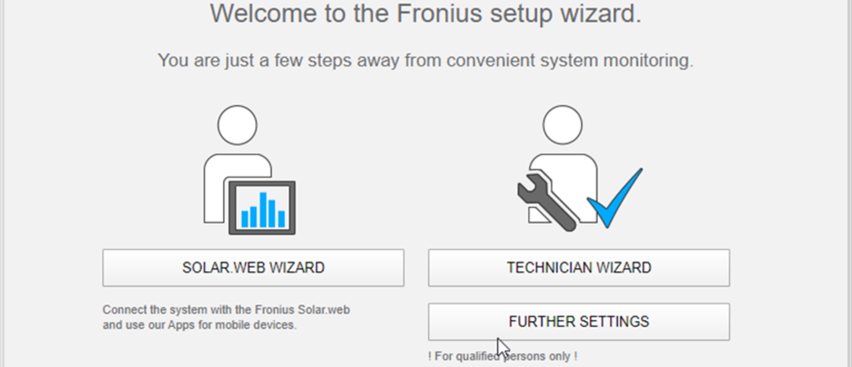
The technician wizard is intended for the installer and contains standard-specific settings. Running the technician wizard is optional.
If the technician wizard is run, it is vital to note the service password that is issued. This service password is necessary for setting the "DNO Editor" menu item.
If the technician wizard is not run, no specifications regarding power reduction are set.
Running the Fronius Solar.web wizards is mandatory.
6Run the Fronius Solar.web wizards and follow the instructions
The Fronius Solar.web homepage is displayed,
or
the Fronius Datamanager 2.0 web page is displayed.
7Where necessary, run the technician wizard and follow the instructions
Further information on Fronius Datamanager 2.0
Further information on the Fronius Datamanager 2.0 and other start-up options can be found at: | |
 | → http://www.fronius.com/QR-link/4204260191DE |
Controls and indicators
Controls and displays

Item | Description |
|---|---|
(1) | Display |
| |
(2) | Initialisation LED (red) lights up
|
(3) | Status LED (orange) lights up
|
(4) | Operating status LED (green) lights up
|
| |
(5) | "Left/up" key |
(6) | "Down/right" key |
(7) | "Menu/Esc" key |
(8) | "Enter" key |
The keys operate capacitively. Exposure to water may impair their function. If necessary, wipe the keys dry with a cloth to ensure optimum functionality.
Controls and displays
Item | Description |
|---|---|
(1) | Display |
| |
(2) | Initialisation LED (red) lights up
|
(3) | Status LED (orange) lights up
|
(4) | Operating status LED (green) lights up
|
| |
(5) | "Left/up" key |
(6) | "Down/right" key |
(7) | "Menu/Esc" key |
(8) | "Enter" key |
The keys operate capacitively. Exposure to water may impair their function. If necessary, wipe the keys dry with a cloth to ensure optimum functionality.
Display
Power for the display comes from the mains voltage. Depending on the setting selected in the Setup menu, the display can be kept on all day. (For night mode, see section Display settings)
IMPORTANT! The display of the inverter is not a calibrated measuring device.
A slight deviation from the utility meter of the energy company is system-related. A calibrated meter will be needed to calculate the bills for the energy company.

Display areas, display mode

Display areas in Setup mode
| (*) | Scroll bar |
| (**) | Energy Manager icon is displayed when the "Energy Manager" function is activated For more information, see section Relay (floating contact switch) |
| (***) | Inv. no. = Inverter DATCOM number, Save symbol - appears briefly while set values are being saved, USB connection - appears if a USB flash drive has been connected |
Switching off current supply and restarting the inverter
Switching off the power supply to the inverter
1
- Turn off the automatic circuit breaker.
- Turn the DC disconnector to the "OFF" switch position.
Switching the inverter on again
- Turn the DC disconnector to the "ON" switch position.
- Switch on the automatic circuit breaker.
Switching off the power supply to the inverter
1
- Turn off the automatic circuit breaker.
- Turn the DC disconnector to the "OFF" switch position.
Switching the inverter on again
- Turn the DC disconnector to the "ON" switch position.
- Switch on the automatic circuit breaker.
Installation
Installation location and position
Explanation of safety notices
DANGER!
Indicates immediate danger.
If not avoided, death or serious injury will result.
WARNING!
Indicates a potentially hazardous situation.
If not avoided, death or serious injury may result.
CAUTION!
Indicates a situation where damage or injury could occur.
If not avoided, minor injury and/or damage to property may result.
NOTE!
Indicates a risk of flawed results and possible damage to the equipment.
Safety
WARNING!
Danger due to incorrect operation and incorrectly performed work.
This can result in serious injury and damage to property.
Only qualified personnel are authorised to commission your inverter and only within the scope of the respective technical regulations.
Read the Installation and Operating Instructions before installing and commissioning the equipment.
WARNING!
Danger due to work that has been carried out incorrectly.
This may result in serious injury and damage to property.
Surge protective devices must only ever be installed and connected by a qualified electrical installation engineer!
Follow the safety rules.
Ensure that both the AC side and the DC side of the inverter are de-energised before carrying out any installation and connection work.
Fire prevention
CAUTION!
Danger due to poor or unprofessional installation.
This may result in damage to inverters and other live photovoltaic system components.
Poor or unprofessional installation can cause overheating of cables and terminal connections and result in arcs. These can cause heat damage, which in turn may lead to fires.
Observe the following when connecting AC and DC cables:
Tighten all terminals to the torque specified in the Operating Instructions
Tighten all grounding terminals (PE / GND), including free ones, to the torque specified in the Operating Instructions
Do not overload cables
Check cables for damage and verify that they are laid correctly
Take note of the safety instructions, Operating Instructions and any local connection regulations
Using fastening screws, always screw the inverter firmly to the mounting bracket to the torque specified in the Operating Instructions.
Ensure that the fastening screws are tight before starting the inverter!
IMPORTANT! Fronius will not accept any costs associated with production downtimes, installer costs, etc., that may arise as the result of a detected arc and its consequences. Fronius accepts no liability for fires that can occur despite the presence of the integrated Arc Fault Circuit Interrupter / interruption system (e.g. fires caused by a parallel arc).
IMPORTANT! After an arc has been detected, the entire photovoltaic system must be checked for possible damage before resetting the inverter.
Observe the manufacturer's connection, Installation and Operating Instructions at all times. To reduce the hazard potential to a minimum, perform all installation and connection work carefully according to the instructions and regulations.
Refer to the device Installation Instructions for the tightening torques to be used at the relevant terminal connections.
Proper use/intended purpose
Utilisation not in accordance with the intended purpose comprises:
- Any use above and beyond this purpose
- Making any modifications to the inverter that have not been expressly approved by Fronius
- the installation of components that are not distributed or expressly approved by Fronius.
Fronius shall not be liable for any damage resulting from such action.
No warranty claims will be entertained.
- Carefully reading and obeying all the instructions and all the safety and danger notices in the Operating Instructions and Installation Instructions
- Performing all stipulated maintenance work
- Installation as specified in the Installation Instructions
When designing the photovoltaic system, ensure that all components are operated within their permitted operating ranges at all times.
Observe all the measures recommended by the solar module manufacturer to ensure that the solar module retains its properties in the long term.
Obey the regulations of the power supply company regarding connection methods and energy fed into the grid.
Choice of location
 |
| The inverter is suitable for indoor installation. |
 |
| The inverter is suitable for outdoor installation. Because of its IP 66 protection class, the inverter is resistant to water jets from any direction and can also be used in damp environments. |
  |
| In order to minimise the heating up of the inverter, do not expose it to direct insolation. The inverter should be installed in a protected location, for example, e.g. in the area of the PV modules or under an overhanging roof. |
  |
| UDCmax at an altitude of: IMPORTANT! The inverter must not be installed or used at altitudes above 3400 m. |
 |
| Do not install the inverter in:
|
 |
| During certain operating phases the inverter may produce a slight noise. For this reason it should not be installed in an occupied living area. |
 |
| Do not install the inverter in:
|
 |
| All inverters are designed to be dust-tight. However, in areas with a heavy build-up of dust, the thermal efficiency may still be impaired by dust forming on the cooling surfaces. Regular cleaning is necessary in such situations. We therefore recommend not installing the device in areas and environments with high dust accumulation. |
 |
| Do not install the inverter in:
|
Installation position
  | The inverter is suitable for vertical installation on a vertical wall or column. |
 | The inverter is suitable for a horizontal installation position. |
 | The inverter is suitable for installation on a sloping surface. |
|
|
 | Do not install the inverter on a sloping surface with its connection sockets at the top. |
 | Do not install the inverter at an angle on a vertical wall or column. |
 | Do not install the inverter horizontally on a vertical wall or pillar. |
  | Do not install the inverter on a vertical wall or pillar with its connection sockets facing upwards. |
 | Do not install the inverter overhanging with the connection sockets at the top. |
 | Do not install the inverter overhanging with the connection sockets at the bottom. |
 | Do not install the inverter on the ceiling. |
General comments regarding choice of location
Please note the following criteria when choosing a location for the inverter:

Only install on a solid, non-flammable surface | ||
Max. ambient temperatures: -25 °C / +60 °C | ||
Relative humidity: 0-100% | ||
The airflow within the inverter is from the right to the top (cold air taken in from the right, hot air dissipated out of the top). | ||
When installing the inverter in a switch cabinet or similar closed environment, it is necessary to make sure that the hot air that develops will be dissipated by forced-air ventilation. | ||
If the inverter is to be installed on the outer wall of a cattle shed, maintain a minimum all-round clearance of 2 m between the inverter and all ventilation and other openings in the building. |
Attaching the Mounting Bracket
Safety
WARNING!
Danger of residual voltage from capacitors.
This may result in an electric shock.
Wait for the capacitors to discharge. The discharge time is indicated on the inverter.
CAUTION!
Danger due to dirt or water on the terminals and contacts of the inverter's connection area.
This may result in damage to the inverter.
When drilling, ensure that terminals and contacts in the connection area do not become dirty or wet.
The mounting bracket without the power stage set does not correspond to the protection class of the entire inverter and must therefore not be exposed to external weather influences over a longer period of time without protection. The mounting bracket is protected when the inverter is suspended in the mounting bracket and firmly screwed to it.
The mounting bracket should be protected from dirt and moisture during installation.
IMPORTANT!
Degree of protection IP 66 is only applicable if- the inverter is placed in the mounting bracket and permanently attached using screws,
- the cover for the data communication area is permanently attached to the inverter with screws.
Degree of protection IP 20 applies to the mounting bracket with no inverter.
Selecting wall plugs and screws
Important! Different fixings may be required to fit the mounting bracket depending on the type of underlying surface. Fixings are therefore not included in the scope of supply of the inverter. The installer is responsible for selecting the right type of fixing.
Recommended screws
To install the inverter, we recommend the use of steel or aluminium screws with a diameter of 6 - 8 mm.
Opening the inverter
WARNING!
Danger from inadequate ground conductor connection.
This can result in serious injury and damage to property.
The housing screws provide a suitable ground conductor connection for earthing the housing and must NOT be replaced by any other screws that do not provide a reliable ground conductor connection.
1
2
3
4

Fitting the mounting bracket to a wall
1
2
3
Installing the mounting bracket on a mast or beam

When installing the inverter on a mast or support, Fronius recommends the "Pole Clamp" kit from Rittal GmbH (order no. SZ 2584.000).
This kit enables the inverter to be installed on round or rectangular masts with the following diameters: Æ from 40 to 190 mm (round mast), ÿ from 50 to 150 mm (rectangular mast)
Fitting the mounting bracket to metal supports
NOTE!
When mounted on metal supports, the inverter must not be exposed to rainwater or splashing water from the rear.
Provide suitable rainwater protection or splash water protection.
The mounting bracket must be securely screwed to at least four points.
1
Do not warp or deform the mounting bracket
IMPORTANT! When fitting the mounting bracket to the wall, ensure that the mounting bracket does not become warped or deformed.


Connecting the inverter to the public grid (AC side)
Safety
WARNING!
Danger due to incorrect operation and incorrectly performed work.
This may result in serious injury and damage to property.
Only qualified staff are authorised to commission your inverter and only within the scope of the respective technical regulations.
Read the Installation and Operating Instructions before installing and commissioning the equipment.
WARNING!
Danger due to grid voltage and DC voltage from solar modules that are exposed to light.
This may result in an electric shock.
Ensure that both the AC side and the DC side of the inverter are de-energised before carrying out any connection work.
Only an authorised electrical engineer is permitted to connect this equipment to the public grid.
CAUTION!
Danger due to incorrectly tightened terminals.
This may result in heat damage to the inverter, which may lead to fire.
When connecting AC and DC cables, ensure that all the terminals are tightened to the specified torque.
Monitoring the grid
To provide the best possible grid monitoring, the resistance in the leads to the AC-side terminals should be as low as possible.
Type of AC cable
The following types of AC cable can be connected to the AC terminals of the inverter:
 |
|
Preparing the aluminium cables for connection
The AC-side terminals are suitable for connecting single-wire, round aluminium cables. Because of the formation of a non-conductive oxide layer due to the reaction of aluminium with air, the following points must be considered when connecting aluminium cables:
- the reduced rated currents for aluminium cables
- the connection conditions listed below
Always follow the cable manufacturer instructions when using aluminium cables.
When designing cable cross-sections, take local regulations into account.
Connection conditions:
1Carefully clean the oxide layer from the bare end of the cable by scraping it, e.g. with a knife
IMPORTANT! Do not use brushes, files or emery paper, as the aluminium particles get trapped and can be transferred to other conductors.
2Once the oxide layer is removed, rub the end of the cable with a neutral grease, such as non-acidic and non-alkaline Vaseline
3Immediately connect the cable end to the terminal
IMPORTANT!Repeat the procedure if the cable has been disconnected and is to be re-connected.
AC terminals

Fronius Symo Advanced
| PE | Ground conductor / earthing |
| L1-L3 | Phase conductor |
| N | Neutral conductor |
Max. cross-section of each conductor cable:
16 mm²
Min. cross-section of each conductor cable:
in accordance with the fuse rating on the AC side, but at least 2.5 mm²
The AC cables can be connected to the AC terminals without ferrules.
M32 (Ø 18-25 mm) mounted
M32 (Ø 7-15 mm) enclosed
IMPORTANT! When using ferrules for AC cables with a cross-section of 16 mm², the ferrules must be crimped with a right-angled cross-section.
The use of ferrules with insulating collars is only permitted up to a max. cable cross-section of 10 mm².
For a power category of 15-17.5 kW, an M32 PG gland is fitted (ø 18-25 mm) and an M32 PG gland (ø 7-15 mm) supplied.
Cross section of the AC cable
When using an M32 metric screw joint (reducer removed):
Cable diameter 11 - 21 mm(with a cable diameter of 11 mm the strain-relief force is reduced from 100 N to a maximum of 80 N)
With cable diameters greater than 21 mm, the M32 screw joint must be replaced by an M32 screw joint with a larger clamping area - item number: 42,0407,0780 – strain-relief device M32x1.5 clamping area 18–25.
Connecting the inverter to the public grid (AC)
- Form loops with the AC cables when connecting them to the AC terminals.
- When securing the AC cables using a metric screw joint, ensure that the loops do not protrude beyond the connection area.
Otherwise, under certain circumstances it may no longer be possible to close the inverter.
IMPORTANT!- Make sure that the grid's neutral conductor is grounded. This may not be the case for IT grids (insulated grids with no earthing); it will then not be possible to use the inverter.
- The neutral conductor must be connected in order to operate the inverter. A neutral conductor that is too small may adversely affect the inverter feeding energy into the grid. The neutral conductor must have an amperage of at least 1 A.
IMPORTANT! The PE ground conductor of the AC cable must be laid in such a way that it is the last to be disconnected in the event that the strain-relief device should fail.
This can be ensured, for example, by making it somewhat longer and by laying it in a loop.
1
2
3
The fastening screw must also be tightened for an unassigned ground conductor (PE) connection.
IMPORTANT! Observe the torque values marked on the side underneath the terminals.
Torque (Nm / lbf.in.) → see information printed next to the terminal

If AC cables are laid over the shaft of the DC main switch or across the connection block of the DC main switch, they may be damaged when the inverter is swung in or they may even prevent the inverter from being fully swung in.
IMPORTANT! Do not lay the AC cable over the shaft of the DC main switch!
Do not lay the AC cable across the DC main switch connection block or the AC connection block!
AC cable must not protrude over the edge of the housing.
If overlength AC or DC cables are to be laid in loops in the connection area, attach the cables with cable ties to the eyelets provided on the top and bottom of the connection block.

Maximum fuse rating on alternating current side

Inverter | Phases | AC output | Maximum output overcurrent protection |
|---|---|---|---|
Symo Advanced 10.0-3-M | 3 | 10,000 W | 80 A |
Symo Advanced 12.5-3-M | 3 | 12,500 W | 80 A |
Symo Advanced 15.0-3-M | 3 | 15,000 W | 80 A |
Symo Advanced 17.5-3-M | 3 | 17,500 W | 80 A |
Symo Advanced 20.0-3-M | 3 | 20,000 W | 80 A |

IMPORTANT!Local regulations, the electricity retailer or other factors may require a residual-current protective device in the AC connection lead.
A type A residual-current circuit breaker with a trip current of at least 100 mA is generally sufficient in this case. In particular cases, and depending on local factors, however, the type A residual-current circuit breaker may trip at the wrong time. For this reason, Fronius recommends that a residual-current circuit breaker that is suitable for frequency converters should be used.
Connection variants on multi-MPP tracker inverters
General
In the case of inverters with multiple MPP trackers like the Fronius Symo Advanced –M, there are 2 independent DC inputs (MPP trackers) available. These two MPP trackers can be wired with a different number of modules.
IMPORTANT! The number of PV modules per MPP tracker per string connection should be the same.
There are 3 terminals for DC+ per MPP tracker. In total there are six terminals for DC-.
In the case of inverters with single MPP trackers like the Fronius Eco, there is 1 DC input (MPP tracker) available. The number of PV modules per string connection should be the same. For the MPP tracker, there are 6 terminals for DC+ and 6 terminals for DC-.
Multi MPP Tracker
Multi MPP tracker mode on both MPP tracker inputs:

Connecting two solar module fields to an inverter with multiple MPP trackers
MPP tracker | Input current | |
|---|---|---|
DC input | Symo Advanced ROW 10-12 | Symo Advanced ROW 15-20 |
If an AFCI (AFPE) according to IEC63027 is prescribed in your installation, an input current per string of maximum 12 A is permitted. | ||
MPP1 | 27 A (IDC NOMINAL) | 33 A (IDC NOMINAL) |
DC+1 | ||
MPP2 | 16.5 A (IDC NOMINAL) | 27 A (IDC NOMINAL) |
DC+2 | ||
Divide the solar module strings between the two MPP tracker inputs (DC+1 and DC+2). The DC- terminals can be used however you wish, as they are internally connected. A clearly numbered connection, but also at the DC terminal, makes it easier to find the correct string, e.g. during an inspection. Set the MPP tracker 2 to the "On" during initial commissioning. The user can of course also do this later in the Basic menu of the inverter.
Single MPP tracker mode on both MPP tracker inputs:
If the solar module strings are connected to a string combiner box (GAK - generator junction box) and the distance to the inverter is bridged by means of a DC string, this DC string can be connected to the inverter as follows.
Jumpering

With jumpering, the MPP tracker 1 and MPP tracker 2 can be jumpered together. This takes place as shown in the image via the connection DC+1 (Pin2) to DC+2 (Pin1).
IMPORTANT! The MPP tracker 2 must be set to OFF. This can be checked in the Basic menu of the inverter.
IMPORTANT! The cable diameter of the DC connection cable and the jumpering must be the same. Jumpering of the DC- terminal is not necessary because it is jumpered internally.
DC Con Kit 25
If your installation requires an AFCI (AFPE) according to IEC63027, do not use a DC Con Kit.
The Fronius DC Con Kit 25 (4,251,015) can be used to connect a solar module string with a cross-section of up to 25 mm² to the inverter.

Set the MPP tracker 2 to "OFF" during initial commissioning. This can also be done later in the Basic menu of the inverter. By using the DC Con Kit 25, the DC strings of the connected DC lines are divided equally between both inputs.

PV cable connection torque DC Con Kit 25: 5.5 Nm / 50 lb-in
DC Con Kit 35
If your installation requires an AFCI (AFPE) according to IEC63027, do not use a DC Con Kit.
The Fronius DC Con Kit 35 (4,251,029) can be used to connect a PV string with a cross-section of up to 35 mm² to the inverter.

Set the MPP tracker 2 to "OFF" during initial commissioning. This can also be done subsequently in the Basic menu of the inverter.
By using the DC Con Kit 35, the DC strings of the connected DC lines are divided equally between the two inputs.

PV cable connection torque DC Con Kit 35: 3 Nm
Connecting solar module strings to the inverter
Safety
WARNING!
Danger due to incorrect operation and incorrectly performed work.
This can result in serious injury and damage to property.
Only qualified personnel are authorised to commission your inverter and only within the scope of the respective technical regulations.
Read the Installation and Operating Instructions before installing and commissioning the equipment.
WARNING!
Danger due to grid voltage and DC voltage from solar modules that are exposed to light.
This may result in an electric shock.
Prior to any connection work, disconnect the inverter on the AC side and the DC side.
Only an authorised electrical engineer is permitted to connect this equipment to the public grid.
WARNING!
Danger from grid voltage and DC voltage from solar modules.
This may result in an electric shock.
The DC main switch is only to be used to de-energise the power stage set. The connection area is still live when the DC main switch is switched off.
Ensure that the power stage set and connection area are disconnected from one another before carrying out any maintenance or service tasks.
The power stage set, which is enclosed in a separate housing, must only be disconnected from the connection area when in a de-energized state.
Maintenance and servicing in the power stage set of the inverter must only be carried out by Fronius-trained service technicians.
CAUTION!
Danger due to incorrectly tightened terminals.
This may result in heat damage to the inverter, which may lead to fire.
When connecting AC and DC cables, ensure that all the terminals are tightened to the specified torque.
CAUTION!
Danger due to overloading.
This may result in damage to the inverter.
The maximum amperage when connecting to a single DC terminal is 33 A.
Connect the DC+ and DC- cables to the DC+ and DC- terminals on the inverter, taking care to ensure that the polarity is correct.
Observe the maximum DC input voltage.
IMPORTANT! The solar modules connected to the inverter must comply with the IEC 61730 Class A standard.
IMPORTANT! When photovoltaic modules are exposed to light, they supply current to the inverter.
General comments regarding PV modules
To enable suitable PV modules to be chosen and to use the inverter as efficiently as possible, it is important to bear the following points in mind:
- If insolation is constant and the temperature is falling, the open-circuit voltage of the PV modules will increase. The open-circuit voltage must not exceed the maximum permissible system voltage. If the open-circuit voltage exceeds the specified values, the inverter will be destroyed and all warranty claims will be forfeited.
- The temperature coefficients on the data sheet of the PV modules must be observed.
- Exact values for sizing the solar modules can be obtained using suitable calculation tools, such as the Fronius Solar.creator (creator.fronius.com).
IMPORTANT! Before connecting up the solar modules, check that the voltage for the solar modules specified by the manufacturer corresponds to the actual measured voltage.
DC terminals

Max. cross-section of each DC cable:
16 mm²
Min. cross-section of each DC cable:
2.5 mm²
The DC cables can be connected to the DC terminals without ferrules.
IMPORTANT! When using ferrules for DC cables with a cross-section of 16 mm², the ferrules must be crimped with a right-angled cross-section.
The use of ferrules with insulating collars is only permitted up to a max. cable cross-section of 10 mm².

For double insulated DC connection leads with a cable diameter greater than 6 mm, 70 mm of the outer jacket must be stripped in order to connect the cable to the DC terminal.
IMPORTANT! To ensure effective strain relief of the solar module strings, only use cables with identical cross-sections.
Connecting aluminium cables
The DC-side terminals are suitable for connecting single-wire, round aluminium cables. Because of the formation of a non-conductive oxide layer due to the reaction of aluminium with air, the following points must be considered when connecting aluminium cables:
- the reduced rated currents for aluminium cables
- the connection conditions listed below
IMPORTANT! Always follow the cable manufacturer instructions when using aluminium cables.
IMPORTANT! When designing cable cross-sections, take local regulations into account.
Connection conditions:
1Carefully clean the oxide layer from the bare end of the cable by scraping it, e.g. with a knife
IMPORTANT! Do not use brushes, files or emery paper, as the aluminium particles get trapped and can be transferred to other conductors.
2Once the oxide layer is removed, rub the end of the cable with a neutral grease, such as non-acidic and non-alkaline Vaseline
3Immediately connect the cable end to the terminal
IMPORTANT! Repeat the procedure if the cable has been disconnected and is to be re-connected.
Solar module strings - checking the polarity and voltage
CAUTION!
Danger due to incorrect polarity and voltage.
This may result in damage to the inverter.
Check the polarity and voltage of the solar module strings before making the connection. The voltage must not exceed the following values:
When installed between 0 and 2000 m above sea level: 1000 V
When installed between 2001 and 2500 m above sea level: 950 V
When installed between 2501 and 3000 m above sea level: 900 V
When installed between 3001 and 3400 m above sea level: 850 V
the Fronius Symo Advanced must not be installed at an altitude exceeding 3400 m above sea level

Connecting the solar module strings to the inverter
IMPORTANT! Only break out as many target break points as the number of cables that are provided (e.g. if there are 2 DC cables, then break out 2 recesses).
IMPORTANT! Fronius Eco: check the string fuses used (type and rating) before connecting the solar module strings to the inverter.
1
2
3
4
5
6
7
IMPORTANT! Observe the torque values marked on the side underneath the terminals.
8
9

If DC cables are laid over the shaft of the DC main switch or across the connection block of the DC main switch, they may be damaged when the inverter is swung in or they may even prevent the inverter from being swung in.
IMPORTANT!
Do not lay DC cables over the shaft of the DC main switch
or across the AC connection block or the DC main switch connection block.
DC cable must not protrude beyond the edge of the housing!
Data communication
Permitted cables for the data communication area

Permitted cables for the data communication area
Routing data communication cables
IMPORTANT! Operating the inverter with one option card and two broken-out option card slots is not permitted.
To cater for this eventuality, a suitable blanking cover (item number 42,0405,2094) is available from Fronius as an option.
IMPORTANT! If data communication cables are wired into the inverter, observe the following points:
- Depending on the number and cross-section of the data communication cables that are being introduced, take the relevant blanking plugs out of the sealing insert and insert the data communication cables.
- The relevant blanking plugs must be inserted into the free openings on the sealing insert.
1
2
3
4
Installing the Datamanager in the inverter
WARNING!
Danger of residual voltage from capacitors.
This may result in an electric shock.
Wait for the capacitors to discharge. The discharge time is five minutes.
WARNING!
Danger from inadequate ground conductor connection.
This can result in serious injury and damage to property.
The housing screws provide a suitable ground conductor connection for earthing the housing and must NOT be replaced by any other screws that do not provide a reliable ground conductor connection.
IMPORTANT! Observe the ESD guidelines when handling option cards.
IMPORTANT! Only one Fronius Datamanager in master mode is permitted per Fronius Solar Net ring. Switch any other Fronius Datamanagers to slave mode or remove them.
Seal off the unoccupied option card slot by replacing the cover (item number 42,0405,2094); alternatively, use an inverter without a Fronius Datamanager (light version).

IMPORTANT! Only break out one opening for the PC board when installing a Datamanager in the inverter.
1
2
3
4
5
Attaching the inverter to the mounting bracket
Attaching the inverter to the mounting bracket
WARNING!
Danger from inadequate ground conductor connection.
This can result in serious injury and damage to property.
The housing screws provide a suitable ground conductor connection for earthing the housing and must NOT be replaced by any other screws that do not provide a reliable ground conductor connection.
Two people are required to attach the inverter to the mounting bracket, as it is extremely heavy.
IMPORTANT! For safety reasons, the inverter is fitted with a latch that prevents the inverter from being swung into the mounting bracket unless the DC main switch is switched off.- Never attach the inverter to the mounting bracket or swing it in unless the DC main switch is switched off.
- Never use force to attach the inverter or swing it in.
The fastening screws in the data communication area of the inverter are used for securing the inverter to the mounting bracket. Correctly tightened fastening screws are a prerequisite if proper contact is to be established between the inverter and mounting bracket.
CAUTION!
Danger due to incorrectly tightened fastening screws.
This may result in arcs occurring when the inverter is in operation, which may lead to fire.
Always use the specified torque when tightening the fastening screws.

Warranty claims will be void if the screws are tightened using an incorrect torque.
Carry out a visual inspection of the seal on the DATCOM mounting bracket cover and check for any damage. A damaged or faulty DATCOM cover must not be fitted to the device.

1
2
3
4
5
6
7
Attaching the inverter to the mounting bracket
WARNING!
Danger from inadequate ground conductor connection.
This can result in serious injury and damage to property.
The housing screws provide a suitable ground conductor connection for earthing the housing and must NOT be replaced by any other screws that do not provide a reliable ground conductor connection.
Two people are required to attach the inverter to the mounting bracket, as it is extremely heavy.
IMPORTANT! For safety reasons, the inverter is fitted with a latch that prevents the inverter from being swung into the mounting bracket unless the DC main switch is switched off.- Never attach the inverter to the mounting bracket or swing it in unless the DC main switch is switched off.
- Never use force to attach the inverter or swing it in.
The fastening screws in the data communication area of the inverter are used for securing the inverter to the mounting bracket. Correctly tightened fastening screws are a prerequisite if proper contact is to be established between the inverter and mounting bracket.
CAUTION!
Danger due to incorrectly tightened fastening screws.
This may result in arcs occurring when the inverter is in operation, which may lead to fire.
Always use the specified torque when tightening the fastening screws.
Warranty claims will be void if the screws are tightened using an incorrect torque.
Carry out a visual inspection of the seal on the DATCOM mounting bracket cover and check for any damage. A damaged or faulty DATCOM cover must not be fitted to the device.
1
2
3
4
5
6
7
Starting for the first time
Starting the inverter for the first time
WARNING!
Danger due to incorrect operation and incorrectly performed work.
This can result in serious injury and damage to property.
Only qualified personnel are authorised to commission your inverter and only within the scope of the respective technical regulations.
Read the Installation and Operating Instructions before installing and commissioning the equipment.
When starting the inverter for the first time, it is necessary to select various setup settings.
If setup is interrupted before it is complete, it can be restarted by means of an AC reset. An AC reset can be carried out by switching the automatic circuit breaker off and on again.
The country setup can only be set when using the inverter for the first time. If the country setup needs to be changed at a later date, please contact your Technical Support team.
1
2
3
* Country setup examples | ||||||||||||||||||||||||||||||||||||||||||||||||||||||||||||||||||||||||||||||||||||||||||||||||||||||||||||||||||||||||||||||||||||||||||||||||||||||||||||||||||||||||||
|---|---|---|---|---|---|---|---|---|---|---|---|---|---|---|---|---|---|---|---|---|---|---|---|---|---|---|---|---|---|---|---|---|---|---|---|---|---|---|---|---|---|---|---|---|---|---|---|---|---|---|---|---|---|---|---|---|---|---|---|---|---|---|---|---|---|---|---|---|---|---|---|---|---|---|---|---|---|---|---|---|---|---|---|---|---|---|---|---|---|---|---|---|---|---|---|---|---|---|---|---|---|---|---|---|---|---|---|---|---|---|---|---|---|---|---|---|---|---|---|---|---|---|---|---|---|---|---|---|---|---|---|---|---|---|---|---|---|---|---|---|---|---|---|---|---|---|---|---|---|---|---|---|---|---|---|---|---|---|---|---|---|---|---|---|---|---|---|---|---|---|
|
|
| ||||||||||||||||||||||||||||||||||||||||||||||||||||||||||||||||||||||||||||||||||||||||||||||||||||||||||||||||||||||||||||||||||||||||||||||||||||||||||||||||||||||||
4
5
6
7
8
9
Notes regarding maintenance
Maintenance
IMPORTANT! When installed outdoors in a horizontal position: once a year, check that all screw joints are tight!
Maintenance and servicing may only be carried out by Fronius-trained service technicians.
Maintenance
IMPORTANT! When installed outdoors in a horizontal position: once a year, check that all screw joints are tight!
Maintenance and servicing may only be carried out by Fronius-trained service technicians.
Cleaning
Clean the inverter as required with a damp cloth.
Do not use cleaning agents, abrasives solvents or similar to clean the inverter.
Australian Conduits
Tightly sealing the conduits
Ensure that the conduits are tightly sealed.


Tightly sealing the conduits
Ensure that the conduits are tightly sealed.
Seal conduits

NOTE!
Condensation within the conduits can damage the inverter or components of the photovoltaic systems.
To avoid undesirable air circulation and condensation in the conduits:
Seal all conduits being used with a permanently elastic sealant
Seal every incoming and outgoing conduit
Seal both conduit ends.
1
Serial Number Sticker for Customer Use
Serial number sticker for customer use

The serial number of the inverter is located on the rating plate on the bottom of the inverter.
Depending on the installation position of the inverter, the serial number can be difficult to access or read, e.g. if the inverter has been installed in a dark or shaded area.

Two serial number stickers are enclosed with the inverter's installation instructions:
| * | 57 x 20 mm |
| ** | 67 x 20 mm |
These can be affixed by the customer in a visible location of their choosing, e.g. on the front of the inverter or on the Operating Instructions.

Application example:
Serial number sticker on the Operating Instructions or on the front of the inverter
For Australia only:
Affix the DRM Australia sticker in the Datamanager area.
Serial number sticker for customer use
The serial number of the inverter is located on the rating plate on the bottom of the inverter.
Depending on the installation position of the inverter, the serial number can be difficult to access or read, e.g. if the inverter has been installed in a dark or shaded area.
Two serial number stickers are enclosed with the inverter's installation instructions:
| * | 57 x 20 mm |
| ** | 67 x 20 mm |
These can be affixed by the customer in a visible location of their choosing, e.g. on the front of the inverter or on the Operating Instructions.
Application example:
Serial number sticker on the Operating Instructions or on the front of the inverter
For Australia only:
Affix the DRM Australia sticker in the Datamanager area.
Settings
Navigation at the menu level
Activating display backlighting
1Press any key
The display backlighting is activated.
There is an option under "Display Settings - Backlighting" in the SETUP menu to set the display backlighting so that it is on all the time or off all the time.
The display backlighting is activated.
There is an option under "Display Settings - Backlighting" in the SETUP menu to set the display backlighting so that it is on all the time or off all the time.
Automatic deactivation of display backlighting / changing to the "NOW" menu item
If two minutes pass without any button being pressed, the display backlighting switches off automatically and the inverter goes to the "NOW" menu item (assuming the display backlighting is set to AUTO).
The automatic selection of the "NOW" menu item can happen from any position on the menu level, unless the inverter was manually switched into the "Standby" operating mode.
After automatically selecting the "NOW" menu item, the current power of feeding in is displayed.
Opening the menu level
 | 1Press "ESC"  |
 | The display switches to the menu level. 2Using the "Left" or "Right" keys  select the desired menu item select the desired menu item3Press the "Enter" key  to select the desired menu item to select the desired menu item |
- NOW
Displays real-time values - LOG
Data recorded today, during the current calendar year and since the inverter was started for the first time - GRAPH
Day characteristic displays a plot showing the output power during the day. The time axis is scaled automatically. Press the "Back" key to close the display - SETUP
Setup menu - INFO
Information about the device and the software
Values displayed under the NOW menu item
Output power (W) - depending on the device type (MultiString), when the Enter key is pressed, |
AC reactive power (VAr) |
Grid voltage (V) |
Output current (A) |
Grid frequency (Hz) |
Solar voltage (V) - U PV1 from MPP Tracker 1 and U PV2 from MPP Tracker 2 (MPPT1 / MPPT2), if MPP Tracker 2 is activated (see "The Basic menu" - "Menu items in the Basic menu") |
Solar power (A) - I PV1 from MPP Tracker 1 and I PV2 from MPP Tracker 2 (MPPT1 / MPPT2), if MPP Tracker 2 is activated (see "The Basic menu" - "Menu items in the Basic menu") |
Time date - Time and date on the inverter or in the Fronius Solar Net ring |
Values displayed under the LOG menu item
Energy fed in (kWh / MWh) There may be discrepancies compared with values displayed on other measuring instruments because of differences in measuring methods. As far as the billing of the energy fed in is concerned, the only binding display values are those produced by the calibrated measuring instrument provided by the utility company. |
Max. output power (W) |
Yield Like the "Energy fed in" figure, the yield figure may also exhibit discrepancies compared with other measured values. The subitem "Energy yield" in the "Menu items in the Set-up menu" section explains how to select a currency and charge rate. |
CO2 savings The subitem "CO2 factor" in the "Menu items in the Set-up menu" section explains how to set the CO2 factor. |
Maximum grid voltage (V) [phase indicator - neutral or phase - phase] |
Maximum solar voltage (V) |
Operating hours IMPORTANT! In order for the day and year values to be displayed correctly, the time must be set accurately. |
SETUP menu item
Initial setting
The inverter is pre-configured after commissioning has been completely carried out (e.g. using the Installation Wizard) according to the country setup.
The SETUP menu item allows the initial settings of the inverter to be changed easily to bring it in line, as closely as possible, with the preferences and requirements of the user.
Software updates
IMPORTANT! As a result of software updates, you may find that your device has certain functions that are not described in these Operating Instructions, or vice versa. Certain illustrations may also differ slightly from the actual controls on your device, but these controls function in exactly the same way.
Navigating the SETUP menu item
Entering the SETUP menu item | |
 | 1At the menu level, use the "Left" or "Right" keys to select the "SETUP" menu item |
2Press the "Enter" key | |
| |
 | The first entry under the SETUP menu item is displayed: |
Scrolling between the entries | |
 | 3Use the "Up" and "Down" keys  to scroll between the available entries to scroll between the available entries |
Exiting an entry | |
| 4To exit a menu entry, press the "Back" key The menu level appears |
If no key is pressed for 2 minutes:
- The inverter switches from wherever it is on the menu level back to the "NOW" display mode (exception: "Standby" Setup menu item).
- The display backlighting goes out unless it has been set to ON in Display Setting - Backlighting (see Display Setting - Backlighting).
- The power currently being fed in is displayed or the currently active state code is displayed.
Setting menu entries, general
1Open the desired menu
2Use the 'Up' or 'Down' keys to select the desired menu item
3Press "Enter"
The available settings are displayed: |
| The first digit of a value to be set flashes: |
4Use the 'Up' or 'Down' buttons to select the desired setting 5Press the 'Enter' key to save and apply the setting. To discard the setting, press the 'Esc' key. | 4Use the 'Up' or 'Down' keys to select a value for the first digit 5Press "Enter" The second digit of the value flashes. 6Repeat steps 4 and 5 until ... the whole value to be set flashes. | |
| 7Press "Enter" 8Repeat steps 4 - 6 as required for units or other values that are to be set until the appropriate unit or the value flashes. 9Press the 'Enter' key to save and apply the changes. To discard the changes, press the 'Esc' key. | |
The currently selected menu item is displayed. |
| The currently selected menu item is displayed. |
Application example: Setting the time
 | 1Select "Clock" from the Setup menu . |
2Press the "Enter" key | |
|
 | An overview of the values that can be changed is displayed. |
3Use the "Up" and "Down" keys Select "Set time" | |
4Press the "Enter" key |
 | The current time appears. (HH:MM:SS, 24-hour clock), the "tens" digit for the hour will flash. |
5Use the "Up" and "Down" keys  to select a value for the first digit of the code to select a value for the first digit of the code | |
6Press the "Enter" key |
 | The "units" digit for the hour will flash. |
7Repeat steps 5 and 6 to set the "units" digit for the hour, for the minutes and for the seconds until... |
 | the set time starts flashing. |
8Press the "Enter" key | |
| The time is applied and the overview of values that can be changed is displayed. |
4Press the "Esc"  key key |
| The "Clock" item on the Setup menu appears. |
Menu items in the Set-up menu
Standby
Manual activation / deactivation of Standby mode
- No energy is fed into the grid.
- The Startup LED will show steady orange.
- In the display, STANDBY / ENTER are alternately displayed
- In Standby mode, no other menu item at menu level can be accessed or adjusted.
- The automatic switchover into the "NOW" display mode after 2 minutes of keyboard inactivity does not occur.
- Standby mode can only be terminated manually by pressing the "Enter" key.
- Pressing "Enter" at any time will cause energy to resume feeding into the grid, as long as there is no error (state code)
Switching off Standby mode (manually switching off feeding energy into the grid):
1Select the "Standby" item
2Press "Enter" function key
key"STANDBY" and "ENTER" appear alternately on the display.
Standby mode is now active.
The Startup LED shows steady orange.
Resuming feeding energy into the grid:
In standby mode, the display alternates between 'STANDBY' and 'ENTER'.
In standby mode, the display alternates between 'STANDBY' and 'ENTER'.
1Press the "Enter" function key to resume feeding energy into the grid
gridThe "Standby" menu item is displayed.
At the same time, the inverter enters the startup phase.
The operating state LED shows steady green when feeding energy into the grid has been resumed.
DATCOM
Checking data communications, entering the inverter number, protocol settings
Setting range | Status / inverter number / protocol type |
Status | |
Inverter number | |
Setting range | 00 - 99 (00 = inverter address 100) |
Factory setting | 01 |
IMPORTANT! If a number of inverters are linked together in a data communications system, assign a unique address to each one. | |
Protocol type | |
Setting range | Solar Net / Interface * |
Factory setting | Fronius Solar Net |
* The protocol type "Interface" only functions when there is no Datamanager card in the inverter. All Fronius Datamanager cards should be removed from the inverter. | |
USB
Running firmware updates or saving detailed information from the inverter to the USB flash drive
Setting range | Safely remove hardware / Software update / Logging interval |
Safely remove hardware
To remove a USB flash drive from the USB A socket on the plug-in data communications card without losing any data.
- If the OK message appears
- when the "Data transfer" LED stops flashing or comes on steady
Software update
To update the inverter firmware using a USB flash drive.
Procedure:
1Download the relevant firmware update file "froxxxxx.upd"
(under http://www.fronius.com; xxxxx stands for the version number)
(under http://www.fronius.com; xxxxx stands for the version number)
NOTE!
To successfully update the inverter software, the USB flash drive provided for the purpose must not have a hidden partition or any encryption (see chapter "Suitable USB flash drives").
2Save the firmware update file to the highest data level of the USB flash drive
3Open the lid of the data communication area on the inverter
4Plug the USB flash drive containing the firmware update file into the USB socket in the inverter's data communication area
5Select "USB" from the Setup menu, followed by "Software update"
6Press the "Enter" key
7Wait until the version currently installed on the inverter and the new firmware version are displayed for comparison:
- 1st page: Recerbo software (LCD), key controller software (KEY), country setup version (Set)
- 2nd page: Power stage set software (PS1/PS2)
8Press the "Enter" function button after each page
The inverter starts copying the data.
"BOOT" and the progress of storing the individual tests expressed in % are displayed until all the data for all the electronic modules has been copied.
Once copying is complete, the inverter updates the electronic modules as required in sequence.
"BOOT", the affected modules and the update progress in % are displayed.
The final step is for the inverter to update the display.
The display remains dark for approx. 1 minute while the monitoring and status LEDs flash.
Once the firmware update is complete, the inverter enters its start-up phase before going on to start feeding energy into the grid. Unplug the USB flash drive using the "Safely remove hardware" function.
When the inverter firmware is updated, any custom settings that were configured in the Setup menu are retained.
| Logging interval | |
Unit | Minutes | |
Setting range | 30 min. / 20 min./ 15 min./ 10 min./ 5 min./ No log | |
Factory setting | 30 min. | |
|
| |
30 min. | The logging interval is 30 minutes; every 30 minutes new logging data will be saved to the USB flash drive. | |
20 min. |  | |
15 min. | ||
10 min. | ||
5 min. | The logging interval is 5 minutes; every 5 minutes new logging data will be saved to the USB flash drive. | |
No log | No data is saved | |
IMPORTANT! In order for the USB logging function to work correctly the time must be set correctly. Setting the time is discussed in the section "Menu items in the Setup menu" - "Clock".
Relay (floating contact switch)
Status codes (state codes), the status of the inverter (e.g. feeding energy into the grid) or Energy Manager functions can be displayed using the floating switch contact (relay).
Setting range | Relay mode / Relay test / Switch-on point* / Switch-off point* |
* these are only shown if the "E-Manager" function has been activated under "Relay mode".
Relay mode
| |
Setting range | ALL / Permanent / GAF / OFF / ON / E-Manager |
Factory setting | ALL |
Alarm function: | ||
ALL / Permanent: | Switching the floating switch contact for permanent and temporary service codes (e.g. brief interruption to energy being fed into the grid, a service code occurs a certain number of times a day - can be adjusted in the "BASIC" menu) | |
GAF | As soon as GAF mode is selected, the relay is switched on. The relay opens as soon as the power stage set registers an error and goes from normally feeding energy into the grid to being in an error state. This means that the relay can be used for fail-safe functions. Application example | |
Active output: | ||
ON: | The floating NO contact is on all the time the inverter is in operation (as long as the display is not dark or is displaying something). | |
OFF: | The floating NO contact is off. | |
Energy Manager: | ||
E-Manager: | Further details on the "Energy Manager" function may be found in the "Energy Manager" section. | |
Relay test | ||
Switch-on point (only if "Energy Manager" function is activated) | ||
Factory setting | 1000 W |
Setting range | Set switch-off point up to the maximum nominal output of the inverter (W or kW) |
Switch-off point (only if "Energy Manager" function is activated) | |
Factory setting | 500 |
Setting range | 0 to the set switch-on point of the inverter (W or kW) |
Energy Manager
(under Relay menu item)
The "Energy Manager" (E-Manager) function can be used to activate the floating switch contact in such a way that it functions as an actuator.
Thus, a consumer that is connected to the floating switch contact can be controlled by specifying a switch-on or switch-off point that depends on the feed-in power (effective power).
- If the inverter is not feeding any power into the grid
- If the inverter is manually switched to Standby mode
- If the effective power is set to < 10% of the nominal output of the inverter.
To activate the Energy Manager function, select the "E-Manager" item and press the "Enter" key.
When the "Energy Manager" function is running, the "Energy Manager" symbol will appear in the top left corner of the display:
 When the floating NO contact is off (open contact)
 When the floating NC contact is on (closed contact)
To deactivate the Energy Manager function, select a different function (ALL / Permanent / OFF / ON) and press the "Enter" key.
NOTE!
Notes on setting up the switch-on and switch-off points
If the difference between the switch-on and switch-off points is too small, or if there are fluctuations in effective power, the result may be multiple switching cycles.
To avoid switching on and off frequently, the difference between the switch-on and switch-off points should be at least 100 - 200 W.
When choosing the switch-off point, the power consumption of the connected consumer should be taken into account.
When choosing the switch-on point, the weather conditions and anticipated insolation should be taken into account.
Application example
Switch-on point = 2000 W, switch-off point = 1800 W
If the inverter is outputting 2000 W or above, then the floating switch contact on the inverter is switched on.
If the inverter output falls to below 1800 W, the floating switch contact is switched off.
This allows useful applications, such as operating a heat pump or an air-conditioning system using as much self-generated power as possible, to be implemented quickly
Time / Date
Set the time, date, the display format and automatic changeover between summer and winter time
Setting range | Set time / Set date / Time display format / Date display format / Summer/winter time |
Set time | |
Set date | |
Time display format | |
Setting range | 12hrs / 24hrs |
Factory setting | Depends on country setup |
Date display format | |
Setting range | mm/dd/yyyy or dd.mm.yy |
Factory setting | Depends on country setup |
Summer/winter time | |
IMPORTANT! Only use the automatic summer/winter time changeover function if the Fronius Solar Net ring does not include any LAN- or WLAN-compatible system components (e.g. Fronius Datalogger Web, Fronius Datamanager or Fronius Hybridmanager). | |
Setting range | on / off |
Factory setting | on |
IMPORTANT! The time and date must be set accurately in order for the day and year values and for the day characteristic to be displayed correctly. | |
Display settings
Setting range | Language / Night mode / Contrast / Illumination |
Language | |
Setting range | English, German, French, Spanish, Italian, Dutch, Czech, Slovakian, Hungarian, Polish, Turkish, Portuguese, Romanian |
Night mode | |
Setting range | AUTO / ON / OFF |
Factory setting | OFF |
AUTO: | Fronius DATCOM mode is always in effect as long as there is a Fronius Datamanager connected in an active and uninterrupted Fronius Solar Net. | |
ON: | Fronius DATCOM mode is always in effect. The inverter supplies 12 V of DC voltage continuously to power the Fronius Solar Net. The display is always active. IMPORTANT! If Fronius DATCOM night mode is set to ON or AUTO when there are Fronius Solar Net components connected, the inverter's current consumption during the night will increase to around 7 W. | |
OFF: | Fronius DATCOM will not run at night, the inverter therefore does not require any power during the night to supply the Fronius Solar Net with energy. | |
Contrast | ||
Setting range | 0 - 10 |
Factory setting | 5 |
Since the contrast is temperature-dependent, it may be necessary to adjust the setting under the "Contrast" menu item when the environmental conditions change. | |
Illumination | |
The "Illumination" menu item only relates to the inverter display backlighting. | |
Setting range | AUTO / ON / OFF |
Factory setting | AUTO |
AUTO: | The inverter display backlighting is activated by pressing any key. If no key is pressed for 2 minutes, the display backlighting will go off again. | |
ON: | The inverter display backlighting remains permanently on when the inverter is active. | |
OFF: | The inverter display backlighting is permanently switched off. |
ENERGY YIELD
- Counter deviation / Calibration
- Currency
- Feed-in tariff
- CO2 factor
Setting range | Currency / Feed-in tariff |
Counter deviation / calibration | |
Currency | |
Setting range | 3 characters, A-Z |
Feed-in tariff | |
Setting range | 2 digits, 3 decimal places |
Factory setting | (depends on country setup) |
CO2 factor | |
Fan
To check that the fan is working correctly
Setting range | Test fan #1 / Test fan #2 (depending on the device) |
- Use the "Up" and "Down" keys to select the desired fan
- Testing of the selected fan is initiated by clicking "Enter".
- The fan will continue to run until the operator exits the menu by pressing "Esc".
IMPORTANT! Nothing will show on the inverter display if the fan is working. The only way to check how the fan is working is by listening and feeling.
The INFO menu item
Measured values
PV Ins.- Insulation resistance of the PV system
Ext. Lim. - external Limitation
U PV 1 / U PV 2* (U PV 2 is not available on the Fronius Symo 15.0-3 208)
Current DC voltage at the DC input terminals, even if the inverter is feeding no power into the grid whatsoever (from the 1st or 2nd MPP Tracker)
* MPP Tracker 2 must be switched to ON via the Basic menu
GVDPR - Grid voltage-dependent power reduction
Fan #1 - Percentage of target output for fan
PSS status
IMPORTANT! Due to the low level of insolation early in the morning and in the evening, the status codes STATE 306 (Power low) and STATE 307 (DC low) are displayed routinely at these times of day. These status codes do not indicate any kind of fault at this point in time.
The status of the most recent inverter fault can be displayed.
- Press the "Enter" key to see the status of the power stage set and the most recent fault
- Use the "Up" and "Down" keys to scroll through the list
- Press the "Back" key to close the status and fault list
Grid status
- Press the 'Enter' key to see the five most recent grid faults
- Use the 'Up' and 'Down' keys to scroll through the list
- Press the 'Back' key to close the grid fault display
Device information
For displaying the settings that will be of relevance to a power supply company. The values shown will depend on the country setup or the device-specific settings of the inverter.
Display area | General / Country-specific setting / MPP tracker / Grid monitoring / Grid voltage limits / Grid frequency limits / Q-mode / AC power limit / AC voltage derating / Fault Ride Through |
General: | Device type - the exact name of the inverter |
Country-specific setting: | Setup - specified country setup Version - version of country setup Origin activated - indicates that the normal country-specific setup is activated. Alternat. activated - indicates that the alternative country-specific setup is activated (for Fronius Symo Hybrid only) Group - group for updating the inverter software |
MPP Tracker: | Tracker 1 - indicates the set tracking behaviour (MPP AUTO / MPP USER / FIX) |
Grid monitoring: | GMTi - Grid Monitoring Time - start-up time of the inverter in sec (seconds) GMTr - Grid Monitoring Time reconnect - reconnection time in sec (seconds) after a grid fault ULL - U (voltage) Longtime Limit - voltage limit value in V (volts) for the 10-minute average voltage value LLTrip - Longtime Limit Trip - trip time for ULL monitoring, how fast the inverter should switch off |
Grid voltage limits inner limit value: | UImax - upper inner grid voltage in V (volts) TTMax - Trip Time Max - trip time for exceeding the upper inner grid voltage limit value in cyl* UMin - lower inner grid voltage in V (volts) TTMin - Trip Time Min - trip time for falling below the lower inner grid voltage limit value in cyl* *cyl = grid periods (cycles); 1 cyl corresponds to 20 ms at 50 Hz or 16.66 ms at 60 Hz |
Grid voltage limits outer limit value | UMax - upper outer grid voltage in V (volts) TTMax - Trip Time Max - trip time for exceeding the upper outer grid voltage limit value in cyl* UMin - lower outer grid voltage in V (volts) TTMin - Trip Time Min - trip time for falling below the lower outer grid voltage limit value in cyl* *cyl = grid periods (cycles); 1 cyl corresponds to 20 ms at 50 Hz or 16.66 ms at 60 Hz |
Grid frequency limits: | FILmax - upper inner grid frequency in Hz (Hertz) FILmin - lower inner grid frequency in Hz (Hertz) FOLmax - upper outer grid frequency in Hz (Hertz) FOLmin - lower outer grid frequency in Hz (Hertz) |
Q-mode: | Indicates which reactive power setting is currently active on the inverter (e.g. OFF, Q / P, etc.) |
AC power limit including SoftStart indicator and/or AC grid frequency derating: | Max P AC - maximum output power, which can be changed using the "Manual Power Reduction" function GPIS - Gradual Power Incrementation at Startup - indicates (%/sec) whether the SoftStart function is active on the inverter GFDPRe - Grid Frequency Dependent Power Reduction enable limit - indicates the set grid frequency in Hz (Hertz) from when power derating takes place GFDPRv - Grid Frequency Dependent Power Reduction derating gradient - indicates the set grid frequency in %/Hz, how strong power derating is |
AC voltage derating: | GVDPRe - Grid Voltage Depending Power Reduction enable limit - threshold value in V from which voltage-dependent power derating starts GVDPRv - Grid Voltage Depending Power Reduction derating gradient - derating gradient %/V with which the power is reduced Message - indicates whether the dispatch of an info message via Fronius Solar Net is active |
Version
Displays the version and serial numbers of the PC boards in the inverter (e.g. for service purposes)
Display area | Display / Display Software / Integrity Checksum / Memory Card / Memory Card #1 / Power Stage / Power Stage Software / EMI Filter / Power Stage #3 / Power Stage #4 |
Switching the key lock on and off
General
The inverter has a key lock function.
When the key lock is active, the Setup menu is not accessible, i.e. the setup data cannot be changed accidentally (or maliciously).
The code 12321 has to be entered in order to activate / deactivate the key lock.
General
The inverter has a key lock function.
When the key lock is active, the Setup menu is not accessible, i.e. the setup data cannot be changed accidentally (or maliciously).
The code 12321 has to be entered in order to activate / deactivate the key lock.
Switching the key lock on and off
1Press the "Menu" key | |
| The menu level appears. 2Press the unassigned "Menu / Esc" key 5 times  |
 | "Access Code" is displayed in the "CODE" menu; the first digit starts flashing. |
3Enter the code 12321: Use the "Plus" and "Minus" keys to select a value for the first digit of the code | |
4Press the "Enter" key |
 | The second digit flashes. |
5Repeat steps 3 and 4 for the second, third, fourth and fifth digits of the access code until... the selected code starts flashing. 6Press the "Enter" key |
 | "Setup Menu Lock" is displayed in the "LOCK" menu. |
7Use the "Plus" and "Minus" keys to turn the key lock on or off:ON = key lock is on (the Setup menu is not accessible) OFF = key lock is off (the Setup menu is accessible) | |
8Press the "Enter" key |
USB Stick as a Data Logger and for Updating Inverter Software
USB flash drive as a datalogger
If a USB flash drive is connected to the USB A socket it can function as a datalogger for an inverter.
At any time, the logging data stored on the USB flash drive can be- imported into the Fronius Solar.access software using the FLD file that was logged at the same time,
- viewed directly in third-party programs (e.g. Microsoft® Excel) using the CSV file logged at the same time.
Older versions (before Excel 2007) are limited to a maximum of 65,536 rows.
Further information on "Data on a USB flash drive", "Data volume and storage capacity" as well as "Buffer memory" can be found at: | |
 | ® https://manuals.fronius.com/html/4204260426 |
USB flash drive as a datalogger
If a USB flash drive is connected to the USB A socket it can function as a datalogger for an inverter.
At any time, the logging data stored on the USB flash drive can be- imported into the Fronius Solar.access software using the FLD file that was logged at the same time,
- viewed directly in third-party programs (e.g. Microsoft® Excel) using the CSV file logged at the same time.
Older versions (before Excel 2007) are limited to a maximum of 65,536 rows.
Further information on "Data on a USB flash drive", "Data volume and storage capacity" as well as "Buffer memory" can be found at: | |
| ® https://manuals.fronius.com/html/4204260426 |
Data on the USB flash drive
If the USB flash drive is being used as a data logger, three files will be created automatically:
- FRONIUS.sys system file:
This file stores information from the inverter that is irrelevant to the customer. The file must not be deleted separately. Only delete all of the files (sys, fld, csv) at one time. - DALO.fld log file:
A log file for reading the data in the Fronius Solar.access software.
Further details on the Fronius Solar.access software can be found in the "DATCOM Details" operating instructions at http://www.fronius.com - DATA.csv log file:
A log file for reading the data in a spreadsheet program (e.g.: Microsoft® Excel)

Data structure on the USB flash drive
| (1) | USB root directory |
| (2) | Fronius inverters (Fronius Galvo, Fronius Symo, Fronius Primo or Fronius Eco) |
| (3) | Inverter number - can be set in the Setup menu under DATCOM |
If there are several inverters with the same inverter number, the three files will be saved in the same folder. A digit is added to the file name as a suffix (e.g.: DALO_02.fld)
Structure of the CSV file:


| (1) | ID |
| (2) | Inverter no. |
| (3) | Inverter type (DATCOM code) |
| (4) | Logging interval in seconds |
| (5) | Energy in watts per second, relative to the logging interval |
| (6) | Inductive reactive power |
| (7) | Capacitive reactive power |
| (8) | Average values during the logging interval (AC voltage, AC current, DC voltage, DC current) |
| (9) | Additional information |
Data volume and storage capacity
A USB flash drive with a storage capacity of 1 GB can record logging data for roughly seven years at a logging interval of five minutes.
CSV file
CSV files can only store 65,535 lines (data records) (up to Microsoft® Excel 2007; there is no restriction from this version onwards).
At a five-minute logging interval, the 65,535 lines will be written within approximately seven months (CSV data size of approx. 8 MB).
In order to avoid data loss, the CSV file should be backed up to a PC and deleted from the USB flash drive within this seven-month period. If the logging interval is set to a longer period, this time frame will be increased accordingly.
FLD file
The FLD file should not be larger than 16 MB. This will provide enough storage capacity for approximately six years at a logging interval of five minutes.
If the file exceeds the 16 MB limit, it should be backed up to a PC and all of the data on the USB flash drive should be deleted.
After backing up and removing the data, the USB flash drive can be reconnected immediately to resume recording the logging data without any further steps being required.
IMPORTANT! Using a full USB flash drive can lead to data loss or data being overwritten. When using USB flash drives, always ensure that there is sufficient storage capacity on the flash drive.
NOTE!
Risk of USB flash drive becoming full.
This may result in data being lost or overwritten.
When using USB flash drives, always ensure that there is sufficient storage capacity on the flash drive.
Buffer memory
If the USB stick is unplugged (e.g. for data backup purposes), the logging data is written to a buffer memory in the inverter.
As soon as the USB stick is plugged in again, the data is copied automatically from the buffer memory to the stick.
The buffer memory can store a maximum of six logging points. Data is only logged while the inverter is running (output greater than 0 W). The logging interval is permanently set at 30 minutes. Data can be recorded on the buffer memory for a three-hour time period as a result.
When the buffer memory is full, the oldest data in the memory will be overwritten by the next batch of data.
IMPORTANT! The buffer memory requires a permanent power supply.
If there is a power failure while the inverter is in operation, all the data in the buffer memory will be lost. To avoid losing data during the night, the automatic night switch-off facility must be deactivated (switch the "Night Mode" setup parameter to ON - see the Datamanager 2.0 Operating Instructions, section "Setting and displaying the menu items", "Viewing and adjusting parameters in the DATCOM menu item").
On the Fronius Eco or Fronius Symo 15.0-3 208, the buffer memory also functions with just a DC supply.
Suitable USB flash drives
Due to the variety of USB flash drives available on the market, it cannot be guaranteed that every USB flash drive will be detected by the inverter.
Fronius recommends that only certified, industry-grade USB flash drives are used (look out for the USB-IF logo).
The inverter supports USB flash drives with the following file systems:
- FAT12
- FAT16
- FAT32
Fronius recommends that the USB flash drive employed should only be used for recording logging data or updating the inverter software. The USB flash drives should not contain any other data.
USB symbol on the inverter display, e.g. in display mode "NOW":

If the inverter detects a USB flash drive, the USB symbol will appear in the top right corner of the display.
When inserting a USB flash drive, check whether the USB symbol is displayed (it may also flash).
IMPORTANT! Please note for outdoor applications that conventional USB flash drives are often only guaranteed to work within a restricted temperature range.
For outdoor applications ensure that the USB flash drive also functions, for example, at low temperatures.
USB flash drive for updating the inverter software

With the help of the USB flash drive, end customers can also update the inverter software via the SETUP menu: the update file is first saved to the USB flash drive, from where it is then transferred to the inverter.
Removing the USB flash drive
Safety instruction concerning the removal of a USB flash drive: | ||
 |
| IMPORTANT! To avoid any loss of data, a USB flash drive may only be removed if the following conditions are met:
|
The Basic menu
Access the Basic menu
| 1Press the "Menu” buttonThe menu level appears. 2Press the unassigned "Menu / Esc" key 5 times |
| "Access Code" is displayed in the "CODE" menu; the first digit starts flashing. |
3Enter the code 22742: Use the "Plus" and "Minus" keys to select a value for the first digit of the code | |
4Press the "Enter" button |
 | The second digit flashes. |
5Repeat steps 3 and 4 for the second, third, fourth and fifth digits of the access code until... the selected code starts flashing. 6Press the "Enter" button |
The Basic menu appears.
7Use the "Plus" and "Minus" keys to select the desired entry
to select the desired entry8Edit the desired menu item by pressing the "Enter" button
button9Press the "Esc" key to exit the Basic menu
Access the Basic menu
| 1Press the "Menu” buttonThe menu level appears. 2Press the unassigned "Menu / Esc" key 5 times |
| "Access Code" is displayed in the "CODE" menu; the first digit starts flashing. |
3Enter the code 22742: Use the "Plus" and "Minus" keys to select a value for the first digit of the code | |
4Press the "Enter" button |
| The second digit flashes. |
5Repeat steps 3 and 4 for the second, third, fourth and fifth digits of the access code until... the selected code starts flashing. 6Press the "Enter" button |
The Basic menu appears.
7Use the "Plus" and "Minus" keys to select the desired entry
to select the desired entry8Edit the desired menu item by pressing the "Enter" button
button9Press the "Esc" key to exit the Basic menu
Menu items in the Basic menu
The Basic menu is used to set the following parameters, which are important for installing and operating the inverter: |
MPP Tracker 1 / MPP Tracker 2
|
|
USB log book
|
Input signal
|
SMS / relay
|
Isolation setting
|
TOTAL Reset To reset the values to zero, press the "Enter" key. |
Settings if the "DC SPD" option is installed
If the option: DC SPD (surge protection) has been fitted in the inverter, the following menu items will be set by default:
Signal input: Ext Sig.
Triggering method: Warning
Connection type: N/C
Appendix
Status diagnostics and troubleshooting
Status code display
The inverter performs a system self-diagnosis that automatically detects many faults that may occur and shows them on the display. This means you are promptly made aware of malfunctions in the inverter or the photovoltaic system, or of any installation or operating faults.
If the system self-diagnosis has detected a specific fault, the associated status code will be shown on the display.
IMPORTANT! Status codes may sometimes appear briefly as a result of the inverter's control response. If the inverter then continues working with no sign of any problem, this means that there was no fault.
Total failure of the display
- Check the AC voltage on the inverter connection sockets:
the AC voltage must be 220/230 V (+ 10 % / - 5 %) or 380/400 V (+ 10 % / - 5 %).
Class 1 status codes
Class 1 status codes generally only arise momentarily and are caused by the public grid.
Example: The grid frequency is too high and the inverter may not feed any energy into the grid owing to a standard. There is nothing wrong with the device.
The initial response of the inverter is to disconnect itself from the grid. The grid is subsequently checked during the stipulated monitoring period. If no further problem has been detected by the end of this period, then the inverter will resume feeding energy into the grid.
The GPIS SoftStart function is activated according to the country setup:
After cutting out due to an AC error, the output power of the inverter is continuously increased in line with the national guidelines.
Code | Description | Behaviour | Remedy |
|---|---|---|---|
102 | AC voltage too high | Following careful testing and when the grid conditions are within the permissible range again, the inverter will resume feeding energy into the grid. | Check grid connections; |
103 | AC voltage too low | ||
105 | AC frequency too high | ||
106 | AC frequency too low | ||
107 | No AC grid | ||
108 | Stand-alone operation detected | ||
112 | RCMU error |
Class 2 status codes
Code |
| Description |
| Behaviour |
| Remedy |
|---|---|---|---|---|---|---|
240 |
| ArcContinuousFault |
| The status code 240 is displayed for roughly 4 seconds. |
| CAUTION!Danger from damaged components of the photovoltaic system This can result in severe personal injury/damage to property. Before the status "240 - ArcContinuousFault" is confirmed, the entire photovoltaic system in question must be checked for possible damage. Have damaged components repaired by qualified personnel. |
241 |
| ArcContinuousFault |
| The status code 241 is displayed directly after 240, the inverter disconnects from the grid for safety reasons. |
| Before resetting the inverter after a detected arc, check the entire photovoltaic system in question for any damage! |
242 |
| ArcContinuousFault |
| The status code 242 is displayed after resetting the status code 241. |
| Reset the status code by pressing the Enter key. |
244 |
| ArcDetected |
| The status code 244 is displayed. |
| No action required. Feed-in mode is started again automatically after 10 minutes. |
245 |
| Arc Detector self-test failed |
| The inverter disconnects itself from the grid. |
| Perform AC reset; |
*) If the status code is displayed all the time: Notify a Fronius-trained service engineer
**) Fault is rectified automatically. If this status code is displayed all the time, contact your system fitter
Class 3 status codes
Class 3 includes status codes that may occur while feeding energy into the grid, but generally do not cause the process to be interrupted for any length of time.
The inverter disconnects automatically from the grid, the grid is then monitored as specified and the inverter attempts to resume feeding energy into the grid.
Code |
| Description |
| Behaviour |
| Remedy |
|---|---|---|---|---|---|---|
301 |
| Overcurrent (AC) |
| Short-term interruption while feeding energy into the grid. |
| *) |
302 |
| Overcurrent (DC) |
|
| ||
303 |
| DC module overtemperature |
| Short-term interruption while feeding energy into the grid. |
| Purge cooling air openings and heat sink; **) |
304 |
| AC module overtemperature |
|
| ||
305 |
| No power being fed in, despite closed relay |
| Short-term interruption while feeding energy into the grid. |
| **) |
306 |
| PV output too low for feeding energy into the grid |
| Short-term interruption while feeding energy into the grid |
| wait for sufficient level of insolation; |
307 |
| DC low |
|
| ||
IMPORTANT! Due to the low level of insolation early in the morning and in the evening, the status codes 306 (Power low) and 307 (DC low) are displayed routinely at these times of day. These status codes do not indicate any kind of fault. | ||||||
308 |
| Intermediate circuit voltage too high | Short-term interruption while feeding energy into the grid |
| **) | |
309 |
| DC input voltage MPPT 1 too high | ||||
311 |
| Polarity of DC strings reversed | ||||
313 |
| DC input voltage MPPT2 too high | ||||
314 |
| Current sensor calibration timeout |
| Short-term interruption while feeding energy into the grid. |
| *) |
315 |
| AC current sensor error | ||||
316 |
| InterruptCheck fail | ||||
325 |
| Overtemperature in the connection area | ||||
326 |
| Fan 1 error | ||||
327 |
| Fan 2 error | ||||
*) If the status code is displayed all the time: notify a Fronius-trained service engineer
**) Fault is rectified automatically. If this status code keeps recurring, contact your system engineer
Status codes – Class 4
Some of the class 4 status codes necessitate intervention by a Fronius-trained service technician.
Code |
| Description |
| Behaviour |
| Remedy |
|---|---|---|---|---|---|---|
401 |
| Unable to communicate with the power stage set |
| The inverter will automatically attempt to connect again and, if possible, will resume feeding energy into the grid |
| *) |
406 |
| AC module temperature sensor faulty (L1) |
|
| ||
407 |
| AC module temperature sensor faulty (L2) |
|
| ||
408 |
| DC component measured in the grid too high |
|
| ||
412 |
| Fixed voltage mode has been selected instead of MPP voltage mode, and the fixed voltage has been set to too low or too high a value. |
| - |
| **) |
415 |
| Safety cut-out via option card or RECERBO has triggered |
| The inverter is not feeding any energy into the grid. |
| *) |
416 |
| No communication possible between power stage set and control system. |
| The inverter will automatically attempt to connect again and, if possible, will resume feeding energy into the grid |
| *) |
417 |
| Hardware ID problem |
| The inverter will automatically attempt to connect again and, if possible, will resume feeding energy into the grid |
| Update inverter firmware; *) |
419 |
| Unique ID conflict | ||||
420 |
| No communication possible with the Fronius Datamanager | ||||
421 |
| HID range error | ||||
425 |
| Unable to communicate with the power stage set | ||||
426 - 428 |
| Possible hardware fault | ||||
431 |
| Software problem |
| The inverter is not feeding any energy into the grid. |
| Perform AC reset (switch automatic circuit breaker off and on again); update inverter firmware; *) |
436 |
| Functional incompatibility (one or more PC boards in the inverter are not compatible with each other, e.g. after a PC board has been replaced) |
| The inverter will automatically attempt to connect again and, if possible, will resume feeding energy into the grid |
| Update inverter firmware; *) |
437 |
| Power stage set problem | ||||
438 |
| Functional incompatibility (one or more PC boards in the inverter are not compatible with each other, e.g. after a PC board has been replaced) |
| The inverter will automatically attempt to connect again and, if possible, will resume feeding energy into the grid |
| Update inverter firmware; *) |
443 |
| Intermediate circuit voltage too low or asymmetric |
| The inverter is not feeding any energy into the grid. |
| *) |
445 |
|
|
| The inverter is not feeding any energy into the grid. |
| Update inverter firmware; *) |
447 |
| Insulation fault |
| The inverter is not feeding any energy into the grid. |
| *) |
448 |
| Neutral conductor not connected | ||||
450 |
| Guard cannot be found | ||||
451 |
| Memory error detected |
| The inverter will automatically attempt to connect again and, if possible, will resume feeding energy into the grid |
| *) |
452 |
| Communication error between the processors | ||||
453 |
| Grid voltage and power stage set are incompatible | ||||
454 |
| Grid frequency and power stage set are incompatible | ||||
456 |
| Anti-islanding function is no longer being implemented correctly | ||||
457 |
| Grid voltage relay fault | The inverter is not feeding any energy into the grid. | Check AC cable *) | ||
458 | Error when recording measuring signal |
| The inverter is not feeding any energy into the grid. |
| *) | |
459 |
| Error when recording the measuring signal for the insulation test | ||||
460 |
| Reference voltage source for the digital signal processor (DSP) is working out of tolerance | ||||
461 | DSP data memory error | |||||
462 |
| Error during DC feed monitoring routine | ||||
463 |
| Reversed AC polarity, AC connector inserted incorrectly | ||||
474 |
| RCMU sensor faulty | The inverter is not feeding any energy into the grid. | **) | ||
475 |
| Insulation fault (connection between solar module and ground) | ||||
476 |
| Driver supply voltage too low | ||||
479 |
| Intermediate circuit voltage relay is switched off | The inverter will automatically attempt to connect again and, if possible, will resume feeding energy into the grid | *) | ||
480, |
| Functional incompatibility (one or more PC boards in the inverter are not compatible with each other, e.g. after a PC board has been replaced) |
| The inverter is not feeding any energy into the grid. |
| Update inverter firmware; *) |
482 |
| Setup interrupted after initial start-up |
| The inverter is not feeding any energy into the grid. |
| Restart Setup after an AC reset (switch automatic circuit breaker off and on again) |
483 |
| Voltage UDC fixed on MPP2 string out of limits |
| The inverter is not feeding any energy into the grid. |
| Check MPP settings; *) |
485 |
| CAN transmit buffer is full |
| The inverter is not feeding any energy into the grid. |
| Perform AC reset (switch automatic circuit breaker off and on again; *) |
489 |
| Permanent overvoltage on intermediate circuit capacitor (five 479 status codes in a row) |
| The inverter is not feeding any energy into the grid. |
| *) |
*) If the status code is displayed all the time: notify a Fronius-trained service technician
**) If this status code keeps recurring, contact your system engineer
Status codes – Class 5
Class 5 status codes do not generally interfere with feeding energy into the grid, but can cause restrictions. These status codes are displayed until they are acknowledged by pressing a key (however, the inverter continues to operate normally in the background).
Code |
| Description |
| Behaviour |
| Remedy |
|---|---|---|---|---|---|---|
502 |
| Insulation error on the solar modules |
| Warning message is shown on the display |
| **) |
509 |
| No energy fed into the grid in the past 24 hours |
| Warning message is shown on the display |
| Acknowledge status code; |
515 |
| Unable to communicate with filter |
| Warning message on the display |
| *) |
516 |
| No communication possible with the storage unit |
| Storage unit warning message |
| *) |
517 |
| Power derating caused by too high a temperature |
| When power derating occurs, a warning message is shown on the display. |
| If necessary, purge cooling air openings and heat sink; |
518 |
| Internal DSP malfunction |
| Warning message on the display |
| *) |
519 |
| No communication possible with the storage unit |
| Storage unit warning message |
| *) |
520 |
| No energy fed into the grid by MPPT1 in the past 24 hours |
| Warning message is shown on the display |
| Acknowledge status code; |
522 |
| DC low String 1 |
| Warning message on the display |
| *) |
523 |
| DC low String 2 |
| |||
558, |
| Functional incompatibility (one or more PC boards in the inverter are not compatible with each other, e.g. after a PC board has been replaced) |
| Warning message on the display | Update inverter firmware; *) | |
560 |
| Power derating caused by overfrequency |
| Displayed when grid frequency becomes excessively high. The power is reduced. |
| As soon as the grid frequency is back within the permissible range and the inverter has returned to normal operation, the fault is rectified automatically; **) |
564 |
| Functional incompatibility (one or more PC boards in the inverter are not compatible with each other, e.g. after a PC board has been replaced) |
| Warning message on the display |
| Update inverter firmware; *) |
566 |
| Arc detector switched off |
| The status code is displayed every day until the arc detector is reactivated. |
| No error |
568 |
| Incorrect input signal on the multifunction current interface |
| The status code is displayed in the case of an incorrect input signal on the multifunction current interface and with the following setting: |
| Acknowledge status code; |
572 |
| Power limited by the power stage set |
| Power is being limited by the power stage set |
| *) |
573 |
| Undertemperature warning |
| Warning message on the display |
| *) |
581 |
| "Special Purpose Utility-Interactive" (SPUI) setup activated |
| The inverter is no longer compliant with the IEEE1547 and IEEE1574.1 standards because the standalone function has been deactivated, a frequency-dependent power reduction has been activated and the frequency and voltage limits are being changed |
| No error |
*) If the status code is displayed all the time: Notify a Fronius-trained service technician.
**) If this status code keeps recurring, contact your system engineer.
Class 6 status codes
Some of the class 6 status codes necessitate intervention by a Fronius-trained service engineer.
Code |
| Description |
| Behaviour |
| Remedy |
|---|---|---|---|---|---|---|
601 |
| CAN bus is full |
| The inverter is not feeding any energy into the grid. |
| Update inverter firmware; *) |
603 |
| AC module temperature sensor faulty (L3) |
| The inverter will automatically attempt to connect again and, if possible, will resume feeding energy into the grid |
| *) |
604 |
| DC module temperature sensor faulty |
|
| ||
607 |
| RCMU error |
| The inverter is not feeding any energy into the grid. |
| Reset status code by pressing 'Enter'. The inverter resumes the feeding of energy into the grid; if the status code keeps appearing, check the complete photovoltaic system for damage; **) |
608 |
| Functional incompatibility (one or more PC boards in the inverter are not compatible with each other, e.g. after a PC board has been replaced) |
| The inverter is not feeding any energy into the grid. |
| Update inverter firmware; *) |
*) If the status code is displayed all the time: notify a Fronius-trained service engineer
**) Fault is rectified automatically. If this status code keeps recurring, contact your system engineer
Status codes – Class 7
Class 7 status codes relate to the control system, the configuration and inverter data recording, and may directly or indirectly affect the process of feeding energy into the grid.
Code |
| Description |
| Behaviour |
| Remedy |
|---|---|---|---|---|---|---|
701 - 704 |
| Provides information about the internal processor status |
| Warning message on the display |
| *) |
705 |
| Conflict when setting the inverter number (e.g. number already assigned) |
| - |
| Correct inverter number in Setup menu |
706 - 716 |
| Provides information about the internal processor status |
| Warning message on the display |
| *) |
721 |
| EEPROM has been re-initialised |
| Warning message on the display |
| Acknowledge status code; *) |
722 - 730 |
| Provides information about the internal processor status |
| Warning message on the display |
| *) |
731 |
| Initialisation error - USB flash drive is not supported |
| Warning message on the display |
| Check or replace USB flash drive |
732 |
| Initialisation error - Overcurrent on USB flash drive |
| |||
733 |
| No USB flash drive connected |
| Warning message on the display |
| Connect or check USB flash drive; *) |
734 |
| Update file not recognised or not present |
| Warning message on the display |
| Check update file (e.g. for correct file name) |
735 |
| Update file does not match the device, update file too old |
| Warning message on the display, update process is interrupted |
| Check update file |
736 |
| Write or read error occurred |
| Warning message on the display |
| Check USB flash drive and the data contained on it or replace USB flash drive |
737 |
| File could not be opened |
| Warning message on the display |
| Remove and then reinsert USB flash drive; check or replace USB flash drive |
738 |
| Log file cannot be saved (e.g. USB flash drive is write-protected or full) |
| Warning message on the display |
| Create some storage space, remove write protection, if necessary check or replace USB flash drive; *) |
740 |
| Initialisation error - error in file system on USB flash drive |
| Warning message on the display |
| Check USB flash drive; reformat on PC for FAT12, FAT16 or FAT32 |
741 |
| Error during recording of logging data |
| Warning message on the display |
| Remove and then reinsert USB flash drive; check or replace USB flash drive |
743 |
| Error occurred during update process |
| Warning message on the display |
| Repeat update process, check USB flash drive; *) |
745 |
| Update file corrupt |
| Warning message on the display, update process is interrupted |
| Download update file again; check or replace USB flash drive; *) |
746 |
| Error occurred during update process |
| Warning message on the display, update process is interrupted |
| Wait for two minutes, then start the update again; *) |
751 |
| Time lost |
| Warning message on the display |
| Reset time and date on the inverter; *) |
752 |
| Real Time Clock module communication error |
| |||
753 |
| Internal error: Real Time Clock module is in emergency mode |
| Time may be inaccurate or lost (feeding energy into the grid normal) |
| Reset time and date on the inverter |
754 - 755 |
| Provides information about the internal processor status |
| Warning message on the display |
| *) |
757 |
| Hardware error in the Real Time Clock module |
| Error message on the display; the inverter is not feeding any energy into the grid |
| *) |
758 |
| Internal error: Real Time Clock module is in emergency mode |
| Time may be inaccurate or lost (feeding energy into the grid normal) |
| Reset time and date on the inverter |
760 |
| Internal hardware error |
| Error message on the display |
| *) |
761 - 765 |
| Provides information about the internal processor status |
| Warning message on the display |
| *) |
766 |
| Emergency power limitation has been activated (max. 750 W) |
| Error message on the display | ||
767 |
| Provides information about the internal processor status |
| Warning message on the display |
| *) |
768 |
| Different power limitation in the hardware modules | ||||
772 |
| Storage unit not available | ||||
773 |
| Software update group 0 (invalid country setup) | ||||
775 |
| PMC power stage set not available |
| Warning message on the display |
| Press 'Enter' key to acknowledge error; *) |
776 |
| Invalid device type | ||||
781 - 794 |
| Provides information about the internal processor status |
| Warning message on the display |
| *) |
*) If the status code is displayed all the time: Notify a Fronius-trained service technician
Class 10 - 12 status codes
1000 - 1299- Provide information on the status of the internal processor program | |
Description | Is of no concern when the inverter is working properly and only appears in the "Status PS" setup parameter. In the event of an actual error, this status code assists Fronius Technical Support during the error analysis. |
Customer service
- an error appears frequently or all the time
- an error appears that is not listed in the tables
Operation in dusty environments
When operating the inverter in extremely dusty environments:
when necessary, clean the cooling elements and fan on the back of the inverter as well as the air intakes at the mounting bracket using clean compressed air.
Technical data
Fronius Symo Advanced 10.0-3-M
Fronius Symo Advanced | 10.0-3-M |
|---|---|
Input data |
|
MPP voltage range | 270–800 V DC |
Max. input voltage | 1000 V DC |
Min. input voltage | 200 V DC |
Max. input current (MPP1 / MPP2) | 27.0 / 16.5 A (14 A for voltages < 420 V) |
Max. input current per string with activated AFCI (AFPE) | 12 A |
Max. short circuit current of the solar modules (ISC PV) (MPP1 / MPP2) | 55.7 / 34 A |
Max. inverter backfeed current to the array 3) | 40.5 / 24.8 A (RMS)4) |
Max. capacity of the module array against earth | 10,000 nF |
Insulation resistance test limit value between module array and earth (on delivery) 7) | 100 kΩ |
Adjustable range of insulation resistance test between module array and earth 6) | 100–10,000 kΩ |
Limit value and tripping time of the sudden residual current monitoring (on delivery) | 30 / 300 mA / ms |
Limit value and tripping time of the continuous residual current monitoring (on delivery) | 300 / 300 mA / ms |
Adjustable range of continuous residual current monitoring 6) | - mA |
Cyclic repetition of the insulation resistance test (on delivery) | 24 h |
Adjustable range for the cyclic repetition of the insulation resistance test | - |
Output data | |
Nominal output power (Pnom) | 10,000 W |
Max. output power | 10,000 W |
Rated apparent power | 10,000 VA |
Nominal mains voltage | 3~ NPE 400 / 230 V or 3~ NPE 380 / 220 |
Min. grid voltage | 150 V / 260 V |
Max. grid voltage | 280 V / 485 V |
Nominal output current at 220 / 230 V | 15.2 / 14.4 A |
Max. output current | 20 A |
Nominal frequency | 50 / 60 Hz 1) |
Initial short circuit alternating current / phase IK | 20 A |
Total harmonic distortion | < 1.75% |
Current (inrush) 5) | 27.2 A peak / |
Power factor (cos phi) | 0–1 ind./cap.2) |
Maximum output fault current / duration | 64 A / 2.34 ms |
General data | |
Maximum efficiency | 97.8% |
European efficiency UDCmin / UDCnom / UDCmax | 95.4 / 97.3 / 96.6% |
Self-consumption at night | 0.7 W & 117 VA |
Cooling | Controlled forced-air ventilation |
Protection class | IP 66 |
Dimensions h x w x d | 725 x 510 x 225 mm |
Weight | 34.8 kg |
Permitted ambient temperature | -25 °C - +60 °C |
Permissible humidity | 0-100% |
EMC emission class | B |
DC / AC overvoltage category | 2 / 3 |
Pollution degree | 2 |
Noise emission | 65 dB(A) (ref. 1pW) |
Inverter topology | Non-insulated transformerless |
Protection devices | |
DC isolation measurement | Integrated |
DC overload performance | Operating point shift, power limiter |
DC disconnector | Integrated |
RCMU | Integrated |
Active anti-islanding method | Frequency conversion method |
AFCI - Arc Fault Circuit Interrupter (Arc Guard) | Integrated |
AFPE (AFCI) classification (according to IEC63027) | F-I-AFPE-1-6-1 |
Fronius Symo Advanced 12.5-3-M
Fronius Symo Advanced | 12.5-3-M |
|---|---|
Input data |
|
MPP voltage range | 320–800 V DC |
Max. input voltage | 1000 V DC |
Min. input voltage | 200 V DC |
Max. input current (MPP1 / MPP2) | 27.0 / 16.5 A (14 A for voltages < 420 V) |
Max. input current per string with activated AFCI (AFPE) | 12 A |
Max. short circuit current of the solar modules (ISC PV) (MPP1 / MPP2) | 55.7 / 34 A |
Max. inverter backfeed current to the array 3) | 40.5 / 24.8 A (RMS)4) |
Insulation resistance test limit value between module array and earth (on delivery) 7) | 100 kΩ |
Adjustable range of insulation resistance test between module array and earth 6) | 100–10,000 kΩ |
Limit value and tripping time of the sudden residual current monitoring (on delivery) | 30 / 300 mA / ms |
Limit value and tripping time of the continuous residual current monitoring (on delivery) | 300 / 300 mA / ms |
Adjustable range of continuous residual current monitoring 6) | - mA |
Cyclic repetition of the insulation resistance test (on delivery) | 24 h |
Adjustable range for the cyclic repetition of the insulation resistance test | - |
Output data |
|
Nominal output power (Pnom) | 12,500 W |
Max. output power | 12,500 W |
Rated apparent power | 12,500 VA |
Nominal mains voltage | 3~ NPE 400 / 230 V or 3~ NPE 380 / 220 |
Min. grid voltage | 150 V / 260 V |
Max. grid voltage | 280 V / 485 V |
Nominal output current at 220 / 230 V | 18.9 / 18.1 A |
Max. output current | 20 A |
Nominal frequency | 50 / 60 Hz 1) |
Initial short circuit alternating current / phase IK | 20 A |
Total harmonic distortion | < 2% |
Current (inrush) 5) | 27.2 A peak / |
Power factor (cos phi) | 0–1 ind./cap.2) |
Maximum output fault current / duration | 64 A / 2.34 ms |
General data | |
Maximum efficiency | 97.8% |
European efficiency UDCmin / UDCnom / UDCmax | 95.7 / 97.5 / 96.9% |
Self-consumption at night | 0.7 W & 117 VA |
Cooling | Controlled forced-air ventilation |
Protection class | IP 66 |
Dimensions h x w x d | 725 x 510 x 225 mm |
Weight | 34.8 kg |
Permitted ambient temperature | -25 °C - +60 °C |
Permissible humidity | 0-100% |
EMC emission class | B |
DC / AC overvoltage category | 2 / 3 |
Pollution degree | 2 |
Noise emission | 65 dB(A) (ref. 1pW) |
Inverter topology | Non-insulated transformerless |
Protection devices | |
DC isolation measurement | Integrated |
DC overload performance | Operating point shift, power limiter |
DC disconnector | Integrated |
RCMU | Integrated |
Active anti-islanding method | Frequency conversion method |
AFCI - Arc Fault Circuit Interrupter (Arc Guard) | Integrated |
AFPE (AFCI) classification (according to IEC63027) | F-I-AFPE-1-6-1 |
Fronius Symo Advanced 15.0-3-M
Fronius Symo Advanced | 15.0-3-M |
|---|---|
Input data |
|
MPP voltage range | 320–800 V DC |
Max. input voltage | 1000 V DC |
Min. input voltage | 200 V DC |
Max. input current (MPP1 / MPP2) | 33.0 / 27.0 A |
Max. input current per string with activated AFCI (AFPE) | 12 A |
Max. short circuit current of the solar modules (ISC PV) (MPP1 / MPP2) | 68 / 55.7 A |
Max. inverter backfeed current to the array 3) | 49.5 / 40.5 A |
Insulation resistance test limit value between module array and earth (on delivery) 7) | 100 kΩ |
Adjustable range of insulation resistance test between module array and earth 6) | 100–10,000 kΩ |
Limit value and tripping time of the sudden residual current monitoring (on delivery) | 30 / 300 mA / ms |
Limit value and tripping time of the continuous residual current monitoring (on delivery) | 300 / 300 mA / ms |
Adjustable range of continuous residual current monitoring 6) | - mA |
Cyclic repetition of the insulation resistance test (on delivery) | 24 h |
Adjustable range for the cyclic repetition of the insulation resistance test | - |
Output data | |
Nominal output power (Pnom) | 15,000 W |
Max. output power | 15,000 W |
Rated apparent power / SRATED | 15,000 VA |
Nominal mains voltage | 3~ NPE 400 / 230 V or 3~ NPE 380 / 220 |
Min. grid voltage | 150 V / 260 V |
Max. grid voltage | 280 V / 485 V |
Nominal output current at 220 / 230 V | 22.7 / 21.7 A |
Max. output current | 32 A |
Nominal frequency | 50 / 60 Hz 1) |
Initial short circuit alternating current / phase IK | 32 A |
Total harmonic distortion | < 1.5% |
Current (inrush) 5) | 27.2 A peak / |
Power factor (cos phi) | 0–1 ind./cap.2) |
Maximum output fault current / duration | 64 A / 2.34 ms |
General data | |
Maximum efficiency | 98% |
European efficiency UDCmin / UDCnom / | 96.2 / 97.6 / 97.1% |
Self-consumption at night | 0.7 W & 117 VA |
Cooling | Controlled forced-air ventilation |
Protection class | IP 66 |
Dimensions h x w x d | 725 x 510 x 225 mm |
Weight | 43.4 kg / 43.2 kg |
Permitted ambient temperature | -25 °C - +60 °C |
Permissible humidity | 0-100% |
EMC emission class | B |
DC / AC overvoltage category | 2 / 3 |
Pollution degree | 2 |
Noise emission | 65 dB(A) (ref. 1pW) |
Inverter topology | Non-insulated transformerless |
Protection devices | |
DC isolation measurement | Integrated |
DC overload performance | Operating point shift, power limiter |
DC disconnector | Integrated |
RCMU | Integrated |
Active anti-islanding method | Frequency conversion method |
AFCI - Arc Fault Circuit Interrupter (Arc Guard) | Integrated |
AFPE (AFCI) classification (according to IEC63027) | F-I-AFPE-1-6-1 |
Fronius Symo Advanced 17.5-3-M
Fronius Symo Advanced | 17.5-3-M |
|---|---|
Input data |
|
MPP voltage range | 370–800 V DC |
Max. input voltage | 1000 V DC |
Min. input voltage | 200 V DC |
Max. input current (MPP1 / MPP2) | 33.0 / 27.0 A |
Max. input current per string with activated AFCI (AFPE) | 12 A |
Max. short circuit current of the solar modules (ISC PV) (MPP1 / MPP2) | 68 / 55.7 A |
Max. inverter backfeed current to the array 3) | 49.5 / 40.5 A |
Insulation resistance test limit value between module array and earth (on delivery) 7) | 100 kΩ |
Adjustable range of insulation resistance test between module array and earth 6) | 100–10,000 kΩ |
Limit value and tripping time of the sudden residual current monitoring (on delivery) | 30 / 300 mA / ms |
Limit value and tripping time of the continuous residual current monitoring (on delivery) | 300 / 300 mA / ms |
Adjustable range of continuous residual current monitoring 6) | - mA |
Cyclic repetition of the insulation resistance test (on delivery) | 24 h |
Adjustable range for the cyclic repetition of the insulation resistance test | - |
Output data |
|
Nominal output power (Pnom) | 17,500 W |
Max. output power | 17,500 W |
Rated apparent power / SRATED | 17,500 VA |
Nominal mains voltage | 3~ NPE 400 / 230 V or 3~ NPE 380 / 220 |
Min. grid voltage | 150 V / 260 V |
Max. grid voltage | 280 V / 485 V |
Nominal output current at 220 / 230 V | 26.5 / 25.4 A |
Max. output current | 32 A |
Nominal frequency | 50 / 60 Hz 1) |
Initial short circuit alternating current / phase IK | 32 A |
Total harmonic distortion | < 1.5% |
Current (inrush) 5) | 27.2 A peak / |
Power factor (cos phi) | 0–1 ind./cap.2) |
Maximum output fault current / duration | 64 A / 2.34 ms |
General data | |
Maximum efficiency | 98% |
European efficiency UDCmin / UDCnom / | 96.4 / 97.7 / 97.2% |
Self-consumption at night | 0.7 W & 117 VA |
Cooling | Controlled forced-air ventilation |
Protection class | IP 66 |
Dimensions h x w x d | 725 x 510 x 225 mm |
Weight | 43.4 kg / 43.2 kg |
Permitted ambient temperature | -25 °C - +60 °C |
Permissible humidity | 0-100% |
EMC emission class | B |
DC / AC overvoltage category | 2 / 3 |
Pollution degree | 2 |
Noise emission | 65 dB(A) (ref. 1pW) |
Inverter topology | Non-insulated transformerless |
Protection devices | |
DC isolation measurement | Integrated |
DC overload performance | Operating point shift, power limiter |
DC disconnector | Integrated |
RCMU | Integrated |
Active anti-islanding method | Frequency conversion method |
AFCI - Arc Fault Circuit Interrupter (Arc Guard) | Integrated |
AFPE (AFCI) classification (according to IEC63027) | F-I-AFPE-1-6-1 |
Fronius Symo Advanced 20.0-3-M
Fronius Symo Advanced | 20.0-3-M |
|---|---|
Input data |
|
MPP voltage range | 420–800 V DC |
Max. input voltage | 1000 V DC |
Min. input voltage | 200 V DC |
Max. input current (MPP1 / MPP2) | 33.0 / 27.0 A |
Max. input current per string with activated AFCI (AFPE) | 12 A |
Max. short circuit current of the solar modules (ISC PV) (MPP1 / MPP2) | 68 / 55.7 A |
Max. inverter backfeed current to the array 3) | 49.5 / 40.5 A |
Insulation resistance test limit value between module array and earth (on delivery) 7) | 100 kΩ |
Adjustable range of insulation resistance test between module array and earth 6) | 100–10,000 kΩ |
Limit value and tripping time of the sudden residual current monitoring (on delivery) | 30 / 300 mA / ms |
Limit value and tripping time of the continuous residual current monitoring (on delivery) | 300 / 300 mA / ms |
Adjustable range of continuous residual current monitoring 6) | - mA |
Cyclic repetition of the insulation resistance test (on delivery) | 24 h |
Adjustable range for the cyclic repetition of the insulation resistance test | - |
Output data |
|
Nominal output power (Pnom) | 20,000 W |
Max. output power | 20,000 W |
Rated apparent power / SRATED | 20,000 VA |
Nominal mains voltage | 3~ NPE 400 / 230 V or 3~ NPE 380 / 220 |
Min. grid voltage | 150 V / 260 V |
Max. grid voltage | 280 V / 485 V |
Nominal output current at 220 / 230 V | 30.3 / 29 A |
Max. output current | 32 A |
Nominal frequency | 50 / 60 Hz 1) |
Initial short circuit alternating current / phase IK | 32 A |
Total harmonic distortion | < 1.25% |
Current (inrush) 5) | 27.2 A peak / |
Power factor (cos phi) | 0–1 ind./cap.2) |
Maximum output fault current / duration | 64 A / 2.34 ms |
General data | |
Maximum efficiency | 98% |
European efficiency UDCmin / UDCnom / | 96.5 / 97.8 / 97.3% |
Self-consumption at night | 0.7 W & 117 VA |
Cooling | Controlled forced-air ventilation |
Protection class | IP 66 |
Dimensions h x w x d | 725 x 510 x 225 mm |
Weight | 43.4 kg / 43.2 kg |
Permitted ambient temperature | -25 °C - +60 °C |
Permissible humidity | 0-100% |
EMC emission class | B |
DC / AC overvoltage category | 2 / 3 |
Pollution degree | 2 |
Noise emission | 65 dB(A) (ref. 1pW) |
Inverter topology | Non-insulated transformerless |
Protection devices | |
DC isolation measurement | Integrated |
DC overload performance | Operating point shift, power limiter |
DC disconnector | Integrated |
RCMU | Integrated |
Active anti-islanding method | Frequency conversion method |
AFCI - Arc Fault Circuit Interrupter (Arc Guard) | Integrated |
AFPE (AFCI) classification (according to IEC63027) | F-I-AFPE-1-6-1 |
Explanation of footnotes
| 1) | The values stated are defaults; the inverter is configured specifically to suit the requirements of the relevant country. |
| 2) | Depending on the country setup or device-specific settings (ind. = inductive; cap. = capacitive). |
| 3) | Maximum current from a defective PV module to all other PV modules. From the inverter itself to the PV side of the inverter, it is 0 A. |
| 4) | Guaranteed by the electrical configuration of the inverter |
| 5) | Current peak when switching on the inverter |
| 6) | Specified values are standard values; depending on the requirement and PV power, these values must be adjusted accordingly. |
| 7) | Specified value is a max. value; exceeding the max. value may negatively affect the function. |
| 8) | ISC PV = ISC max ≥ I SC (STC) x 1.25 according to e.g.: IEC 60364-7-712, NEC 2020, AS/NZS 5033:2021 |
WLAN
WLAN | |
|---|---|
Frequency range | 2412–2462 MHz |
Channels / power used | Channel: 1–11 b,g,n HT20 |
Modulation | 802.11b: DSSS (1 Mbps DBPSK, 2 Mbps DQPSK, 5.5/11 Mbps CCK) |
Integrated DC disconnector Fronius Symo Advanced 10.0-12.5
Settings |
|
|
|
|
|
|---|---|---|---|---|---|
Product name | Benedict LS32 E 7857 | ||||
Rated insulation voltage | 1000 VDC | ||||
Rated impulse withstand voltage | 8 kV | ||||
Suitability for insulation | Yes, DC only | ||||
Utilisation category and / or PV utilisation category | As per IEC/EN 60947-3 utilisation category DC-PV2 | ||||
Rated short-time withstand current (Icw) | Rated short-time withstand current (Icw): 1000 A for 2 poles; 1700 A for 2+2 poles | ||||
Rated short-circuit making capacity (Icm) | Rated short-time withstand current (Icm): 1000 A for 2 poles; 1700 A for 2+2 poles | ||||
Rated breaking capacity | Rated operating voltage (Ue) | Rated operating current (Ie) 2P | I(make) / I(break) 2P | Rated operating current (Ie) 2 + 2P | I(make) / I(break) 2 + 2P |
≤ 500 | 32 | 128 | 50 | 200 | |
600 | 27 | 108 | 35 | 140 | |
700 | 22 | 88 | 22 | 88 | |
800 | 17 | 68 | 17 | 68 | |
900 | 12 | 48 | 12 | 48 | |
1000 | 6 | 24 | 6 | 24 | |
Integrated DC disconnector Fronius Symo Advanced 15.0 - 20.0
Settings |
|
|
|
|
|
|---|---|---|---|---|---|
Product name | Benedict LS32 E 7858 | ||||
Rated insulation voltage | 1000 VDC | ||||
Rated impulse withstand voltage | 8 kV | ||||
Suitability for insulation | Yes, DC only | ||||
Utilisation category and / or PV utilisation category | As per IEC/EN 60947-3 utilisation category DC-PV2 | ||||
Rated short-time withstand current (Icw) | Rated short-time withstand current (Icw): 1400 A for 2 poles; 2400 A for 2+2 poles | ||||
Rated short-circuit making capacity (Icm) | Rated short-time withstand current (Icm): 1400 A for 2 poles; 2400 A for 2+2 poles | ||||
Rated breaking capacity | Rated operating voltage (Ue) | Rated operating current (Ie) 2P | I(make) / I(break) 2P | Rated operating current (Ie) 2 + 2P | I(make) / I(break) 2 + 2P |
≤ 500 | 55 | 220 | 85 | 340 | |
600 | 55 | 220 | 75 | 300 | |
700 | 55 | 220 | 60 | 240 | |
800 | 49 | 196 | 49 | 196 | |
900 | 35 | 140 | 35 | 140 | |
1000 | 20 | 80 | 25 | 100 | |
Applicable standards and guidelines
CE mark
The devices comply with all the requisite and relevant standards and guidelines that form part of the relevant EU Directive, and are therefore permitted to display the CE mark.
Circuit to prevent stand alone operation
The inverter has an approved circuit to prevent stand alone operation.
Grid failure
The standard measurement and safety procedures integrated into the inverter ensure that in the event of a grid failure, the feed-in of energy is immediately interrupted (e.g. switch-off by the energy supplier or damage to lines).
Warranty terms and conditions, and disposal
Fronius manufacturer's warranty
Detailed, country-specific warranty conditions are available at www.fronius.com/solar/warranty.
To obtain the full warranty period for your newly installed Fronius product, please register at www.solarweb.com.
Fronius manufacturer's warranty
Detailed, country-specific warranty conditions are available at www.fronius.com/solar/warranty.
To obtain the full warranty period for your newly installed Fronius product, please register at www.solarweb.com.
Disposal
The manufacturer, Fronius International GmbH, will take back the old device and arrange for it to be professionally recycled. Observe the national regulations for the disposal of electronic equipment.