Safety Instructions
Explanation of warnings and safety instructions
The warnings and safety instructions in these instructions are intended to protect people from possible injury and the product from damage.
DANGER!
Indicates an immediately dangerous situation
Serious injury or death will result if appropriate precautions are not taken.
Action step to escape the situation
WARNING!
Indicates a potentially dangerous situation
Death or serious injury may result if appropriate precautions are not taken.
Action step to escape the situation
CAUTION!
Indicates a potentially dangerous situation
Minor or moderate injury may result if appropriate precautions are not taken.
Action step to escape the situation
NOTE!
Indicates impaired work results and/or damage to the device and components
The warnings and safety instructions are an integral part of these instructions and must always be observed to ensure the safe and proper use of the product.
Explanation of warnings and safety instructions
The warnings and safety instructions in these instructions are intended to protect people from possible injury and the product from damage.
DANGER!
Indicates an immediately dangerous situation
Serious injury or death will result if appropriate precautions are not taken.
Action step to escape the situation
WARNING!
Indicates a potentially dangerous situation
Death or serious injury may result if appropriate precautions are not taken.
Action step to escape the situation
CAUTION!
Indicates a potentially dangerous situation
Minor or moderate injury may result if appropriate precautions are not taken.
Action step to escape the situation
NOTE!
Indicates impaired work results and/or damage to the device and components
The warnings and safety instructions are an integral part of these instructions and must always be observed to ensure the safe and proper use of the product.
General
- injury or death to the operator or a third party,
- damage to the device and other material assets belonging to the operating company,
- inefficient operation of the device.
- be suitably qualified,
- have knowledge of automated welding and
- have read these Operating Instructions and any system component operating instructions in full and follow them carefully.
The Operating Instructions must always be at hand wherever the device is being used. In addition to the Operating Instructions, all applicable local rules and regulations regarding accident prevention and environmental protection must also be followed.
All safety and danger notices on the device must- must be kept in a legible state
- not be damaged/marked
- not be removed
- not be covered, pasted, or painted over
For the location of the safety and danger notices on the device, refer to the section headed "General" in the Operating Instructions for the device.
Before switching on the device, remove any faults that could compromise safety.
Your personal safety is at stake!
Intended use
The cleaning device is intended exclusively for the mechanical cleaning of Fronius robot welding torches in automatic operation. Any other use shall be deemed to be not in accordance with the intended use.
Intended use also means:- Reading these operating instructions in their entirety.
- Following all instructions and safety rules in these operating instructions.
- Complying with the inspection intervals and the performance of all maintenance work.
The device is designed for operation in industry and business.
Environmental Conditions
Operation or storage of the device outside the stipulated area will be deemed as not in accordance with the intended purpose.
Temperature range of the ambient air:- During operation: 0°C to + 40°C (32°F to 104°F)
- During transport and storage: -25°C to +55°C (-13°F to 131°F)
- Up to 50% at 40°C (104°F)
- Up to 90% at 20°C (68°F)
Ambient air: free of dust, acids, corrosive gases or substances, etc.
Altitude above sea level: up to 2000 m (6500 ft.)
Obligations of the Operating Company
- Are familiar with the basic occupational safety and accident prevention regulations and are trained in handling the device
- Have read and understood these Operating Instructions, especially the section "Safety Rules," and have confirmed this with their signature
- Are trained according to the requirements for the work results
The safety-conscious work of the personnel must be checked regularly.
Obligations of Personnel
- Follow the basic regulations for occupational safety and accident prevention
- Read these Operating Instructions, especially the section "Safety Rules," and confirm that they have understood and will follow them by signing
Before leaving the workplace, ensure that no personal injury or property damage can occur in one's absence.
Particular Hazard Areas
Do not linger in the operating area of the robot.
Always integrate the device into a higher-level safety system in a secured area.
If this area has to be accessed for preparatory or maintenance work, ensure that- the entire system is shut down for the duration of access to this area
- and remains shut down to prevent unintended operation, e.g., as a result of a control error.
If untrained operating personnel have access to the device, the compressed air supply to the device must be disconnected for the duration of this access in accordance with "Performance Level d" of ISO 13849-1.
In addition to these Operating Instructions, the safety rules of the robot manufacturer must be followed.
The human body, and, in particular, hands, face and hair, plus items of clothing and all tools, must be kept away from moving components, such as:- the rotating cleaning cutter
- the cleaning motor that moves up and down
- the gas nozzle clamping device that moves in and out
- Wire cutter
Do not touch the cleaning cutter immediately after operation - burning hazard. Follow the special safety regulations for handling the cleaning cutter in the Operating Instructions.
Protect hands, face and eyes from flying parts (chips, etc.) and compressed air/parting agent mixture discharged from the parting-agent injection nozzle.
Covers must only be opened/removed during maintenance, installation and repair work.
During operation:- ensure that all covers are closed, and all side parts have been mounted properly
- keep all covers closed
Personal Protection and Protection of Others
You are exposed to numerous hazards while handling the device. In addition to these Operating Instructions, the safety rules of the manufacturer of the entire welding system must be followed.
Keep persons, especially children, away during the operation of the devices and during the welding process. However, if persons are in the vicinity:- instruct them about all hazards (crush hazard posed by moving mechanical parts, injury hazard from the cleaning cutter, flying chips or similar, discharged compressed air/parting agent mixture, injury hazard due to flying sparks, blinding hazard due to arcs, welding fume hazardous to health, noise exposure, possible hazard due to mains current or welding current, etc.)
- Provide suitable protective equipment, or
- construct suitable protective walls and curtains.
EMC Device Classifications
- Are only designed for use in industrial settings
- Can cause line-bound and radiated interference in other areas
- Satisfy the emissions criteria for residential and industrial areas. This is also true for residential areas in which the energy is supplied from the public low-voltage grid.
EMC device classification as per the rating plate or technical data.
EMC Measures
In certain cases, even though a device complies with the standard limit values for emissions, it may affect the application area for which it was designed (e.g., when there is sensitive equipment at the same location, or if the site where the device is installed is close to either radio or television receivers).
If this is the case, then the operating company is obliged to take appropriate action to rectify the situation.
- Safety devices
- Grid power lines, signal lines, and data transfer lines
- EMC and telecommunications equipment
- Devices for measuring and calibrating
- Grid power supply
- If electromagnetic interference occurs despite a grid connection that complies with regulations, take additional measures (e.g., use a suitable grid filter).
- Control lines
- Keep them as short as possible
- Route them close together (also to avoid EMF problems)
- Route them far from other lines
- Equipotential bonding
- Shield, if necessary
- Shield other devices in the vicinity
- Shield the entire welding installation
EMF measures
- Effects on the health of persons close by, e.g., those with pacemakers and hearing aids
- Persons with pacemakers must seek advice from their doctor before staying in the immediate vicinity of the device and the welding process
- Keep distances between welding power-leads and the head/torso of the welder as great as possible for safety reasons
- Do not carry welding power-leads and hosepacks over your shoulder or wrap them around your body or body parts
Safety Measures at the Setup Location and during Transport
A toppling device can be deadly! Install the device horizontally on a flat, stable surface free of vibration, anchor it securely on the surface, and secure against toppling.
Special regulations apply in areas at risk of fire or explosion- Follow the appropriate national and international regulations.
Use instructions and checks within the company to ensure that the vicinity of the workplace is always clean and organized.
Take care to ensure that the applicable national and regional guidelines and accident prevention regulations are observed when transporting the device, especially guidelines concerning hazards during transport and shipment.
It is essential to conduct a visual inspection of the device to check for damage after it has been transported but before it is commissioned. Have any damage repaired by trained service technicians before commissioning the device.
Safety Measures in Normal Operation
- injury or death to the operator or a third party,
- damage to the device and other material assets belonging to the operating company,
- inefficient operation of the device.
Safety devices that are not fully functional must be repaired before the device is started up.
Never bypass or disable safety devices.
Before starting up the device, ensure that no one can be put in danger.
The device must be examined at least once a week for externally detectable damage and functionality of the safety devices.
- Only use appropriate original parting agents from the manufacturer.
- When handling parting agent, observe the information on the parting agent safety data sheet. The parting agent safety data sheet can be obtained from your service center or via the manufacturer's website.
- Do not mix parting agents from the manufacturer with other parting agents.
- If damage occurs due to the use of other parting agents, the manufacture is not liable for this and all warranty claims are forfeited.
- Properly dispose of used parting agent according to national and international regulations.
Maintenance and repair
It is impossible to guarantee that bought-in parts are designed and manufactured to meet the demands made of them, or that they satisfy safety requirements.
- Use only original spare and wearing parts (also applies to standard parts).
- Do not carry out any modifications, alterations, etc. to the device without the manufacturer's consent.
- Components that are not in perfect condition must be replaced immediately.
- When ordering, please give the exact designation and part number as shown in the spare parts list, as well as the serial number of your device.
The housing screws provide the ground conductor connection for earthing the housing parts.
Only use original housing screws in the correct number and tightened to the specified torque.
Safety Inspection
The manufacturer recommends that a safety inspection of the device be performed at least every 12 months.
A safety inspection by a certified electrician is recommended:- after changes
- after alterations
- after repair, care, and maintenance
- at least every 12 months.
For the safety inspection, follow the appropriate national and international standards and guidelines.
You can obtain more information about the safety inspection and calibration from your service center. The service center will provide the necessary documents upon request.
Safety Symbols
Devices with CE marking satisfy the essential requirements of the relevant directives (e.g. the low-voltage, electromagnetic compatibility, and machinery directives).
Devices marked with the CSA test mark satisfy the requirements of the relevant standards for Canada and the USA.
Disposal
Waste electrical and electronic equipment must be collected separately and recycled in an environmentally sound manner in accordance with the European Directive and national law. Used equipment must be returned to the distributor or through a local authorized collection and disposal system. Proper disposal of the used device promotes sustainable recycling of resources and prevents negative effects on health and the environment.
Packaging materials- Collect separately
- Observe local regulations
- Crush cardboard boxes
Copyright
Copyright of these operating instructions remains with the manufacturer.
Text and illustrations were accurate at the time of printing, subject to change.
We are grateful for suggestions for improvement and information on any discrepancies in the operating instructions.
General
General
Device concept
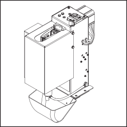
The cleaning device is intended to automatically clean MIG/MAG welding torches. The cleaning device can be used to reliably clean the inside of gas nozzles and the face of the gas nozzles in a range of welding torch geometries. This significantly increases the service life of wearing parts. At the same time, the even application of parting agent prevents the build-up of new dirt.
General
Device concept
The cleaning device is intended to automatically clean MIG/MAG welding torches. The cleaning device can be used to reliably clean the inside of gas nozzles and the face of the gas nozzles in a range of welding torch geometries. This significantly increases the service life of wearing parts. At the same time, the even application of parting agent prevents the build-up of new dirt.
Device concept
The cleaning device is intended to automatically clean MIG/MAG welding torches. The cleaning device can be used to reliably clean the inside of gas nozzles and the face of the gas nozzles in a range of welding torch geometries. This significantly increases the service life of wearing parts. At the same time, the even application of parting agent prevents the build-up of new dirt.
Functionality of the cleaning device
- The gas nozzle clamping device on the front of the cleaning device holds the gas nozzle in place during the cleaning process.
- A cleaning cutter is used for cleaning.
- After cleaning, the parting-agent injection nozzle parting agent is sprayed into the gas nozzle and onto the face of the gas nozzle.
Application areas
The cleaning device is exclusively suited for operation in automation and robot applications and can be used for a range of materials.
Main applications:- Automotive and supply industry
- Equipment engineering
- Chemical plant construction
- Mechanical engineering, rail vehicle construction
- Construction machinery and special-purpose vehicle construction
Warning notices on the cleaning device
The cleaning device has warning notices and a rating plate fitted. These warning notices and the rating plate must not be removed or painted over.
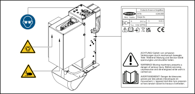
Warning notices on the cleaning device
 | PLEASE NOTE! Risk of serious injury from mechanically moving parts. |
 | Do not use the functions described here until you have fully read and understood the following documents:
|
 | For indoor use only. |
 | CE label – confirms compliance with applicable EU directives and regulations. |
 | WEEE marking – waste electrical and electronic equipment must be collected separately and recycled in an environmentally sound manner in accordance with the European Directive and national law. |
 | UKCA marking – confirms compliance with applicable UK directives and regulations. |
 | Wear eye protection. |
 | Warning before the device switches on automatically. |
 | Warning of hand injuries. |
Transport
Transport equipment
Transport the device using the following transport equipment:
- On a pallet using a counterbalanced lift truck
- On a pallet using a lift truck
- Manually
WARNING!
Danger from devices and objects falling.
This can result in severe personal injury and damage to property.
When transporting the device by counterbalanced lift truck or lift truck, secure the device to prevent it from falling.
Do not turn, brake, or accelerate in a sudden, jerking manner.
Transport equipment
Transport the device using the following transport equipment:
- On a pallet using a counterbalanced lift truck
- On a pallet using a lift truck
- Manually
WARNING!
Danger from devices and objects falling.
This can result in severe personal injury and damage to property.
When transporting the device by counterbalanced lift truck or lift truck, secure the device to prevent it from falling.
Do not turn, brake, or accelerate in a sudden, jerking manner.
Transport Instructions on the packaging
CAUTION!
Danger due to improper transport.
This can result in damage to property.
Follow the transport instructions on the device packaging.
Scope of Supply and Options
Scope of supply
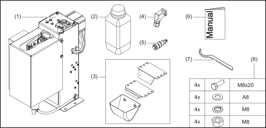
| (1) | Robacta Reamer Single/Twin cleaning device |
| (2) | 2x parting agent containers |
| (3) | Collection container with mounting bracket |
| (4) | Harting Han12P (X1) without cable |
| (5) | Compressed air relief valve |
| (6) | Operating Instructions |
| (7) | Wrench for cleaning motor |
| (8) | Mounting material to assemble the cleaning device:
|
The “Robacta Reamer” parting agent (item number 42.0411.8042) and the cleaning cutter are not included in the scope of supply. Find the right cleaning cutter in the Spare Parts List for the welding torch used: https://spareparts.fronius.com/
Scope of supply
| (1) | Robacta Reamer Single/Twin cleaning device |
| (2) | 2x parting agent containers |
| (3) | Collection container with mounting bracket |
| (4) | Harting Han12P (X1) without cable |
| (5) | Compressed air relief valve |
| (6) | Operating Instructions |
| (7) | Wrench for cleaning motor |
| (8) | Mounting material to assemble the cleaning device:
|
The “Robacta Reamer” parting agent (item number 42.0411.8042) and the cleaning cutter are not included in the scope of supply. Find the right cleaning cutter in the Spare Parts List for the welding torch used: https://spareparts.fronius.com/
Available options
- Work stand
- Suction pipe for parting agent container
- OPT/i TSS TCP Touch Sense
- Cleaning cutter
- Clamping device gas nozzle (TPS, TPS/i)
- GVC (gas volume control)
- Impulse compressed air blowout
Operating controls, connections and mechanical components
Safety
Safety
Please follow the safety rules below when using all the functions described in the "Operating controls, connections, and mechanical components" chapter.
WARNING!
Danger from incorrect operation and work that is not carried out properly.
This can result in serious personal injury and damage to property.
All the work and functions described in this document must only be carried out by technically trained and qualified personnel.
Read and understand this document in full.
Read and understand all safety rules and user documentation for this equipment and all system components.
Safety
Safety
Please follow the safety rules below when using all the functions described in the "Operating controls, connections, and mechanical components" chapter.
WARNING!
Danger from incorrect operation and work that is not carried out properly.
This can result in serious personal injury and damage to property.
All the work and functions described in this document must only be carried out by technically trained and qualified personnel.
Read and understand this document in full.
Read and understand all safety rules and user documentation for this equipment and all system components.
Safety
Please follow the safety rules below when using all the functions described in the "Operating controls, connections, and mechanical components" chapter.
WARNING!
Danger from incorrect operation and work that is not carried out properly.
This can result in serious personal injury and damage to property.
All the work and functions described in this document must only be carried out by technically trained and qualified personnel.
Read and understand this document in full.
Read and understand all safety rules and user documentation for this equipment and all system components.
Operating controls, connections and mechanical components
Operating controls, connections, and mechanical components
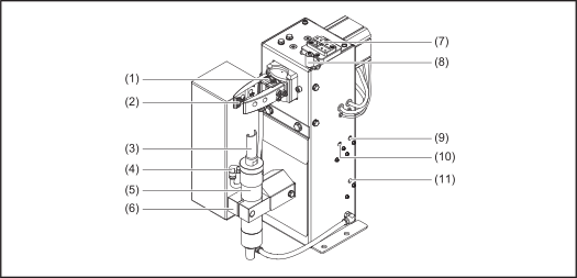
| (1) | Knife / wire cutter (available option) 2x knives for cutting the welding wire (max. 2 welding wires à 1.6 mm diameter). |
| (2) | Clamping device gas nozzle (available option) fixes the gas nozzle during the cleaning process. The clamping device must be selected depending on the gas nozzle used. |
| (3) | Cleaning cutter (available option) |
| (4) | Parting agent injection device includes the parting-agent injection nozzle. The parting-agent injection nozzle ensures that the parting agent only reaches the inside/face of the gas nozzle. |
| (5) | Cleaning motor drives the cleaning cutter. |
| (6) | Lifting device Lifts the cleaning motor with the cleaning cutter into the gas nozzle during the cleaning process. |
| (7) | Touch sense (available option) Gauge for the wear of the contact tip and the exit angle of the wire electrode. |
| (8) | TCP (ToolCenterPoint) with protective cover |
| (9) | Manually check the “Clamp gas nozzle / Cut wire” function. |
| (10) | Manually check the “Spray in release agent” function. |
| (11) | Manually check the “Cleaning motor on / Lifting device up” function. |
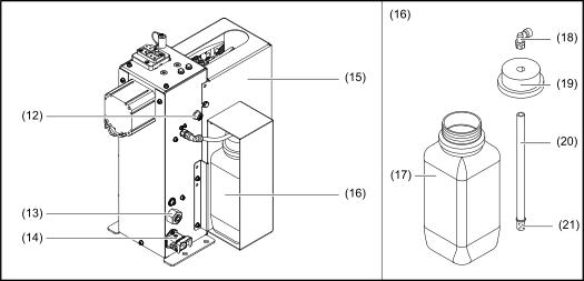
| (12) | Actuator/sensor connection |
| (13) | Compressed air connection socket For supplying dry compressed air at 6 bar (86.99 psi). For more information on compressed air quality, see chapter Specifications for the compressed air supply on page (→). Thread identification for compressed air connection: G ¼” |
| (14) | Harting Han12P (X1) connection socket + 24 V DC power supply |
| (15) | Protective cover |
| (16) | Parting agent container |
| (17) | Capacity of the parting agent container (storage capacity: 1l) |
| (18) | Connection elbow |
| (19) | Closure cap |
| (20) | Suction hose |
| (21) | Intake filter |
- Operating controls, connections and mechanical components
- Operating controls, connections and mechanical components
Operating controls, connections, and mechanical components
| (1) | Knife / wire cutter (available option) 2x knives for cutting the welding wire (max. 2 welding wires à 1.6 mm diameter). |
| (2) | Clamping device gas nozzle (available option) fixes the gas nozzle during the cleaning process. The clamping device must be selected depending on the gas nozzle used. |
| (3) | Cleaning cutter (available option) |
| (4) | Parting agent injection device includes the parting-agent injection nozzle. The parting-agent injection nozzle ensures that the parting agent only reaches the inside/face of the gas nozzle. |
| (5) | Cleaning motor drives the cleaning cutter. |
| (6) | Lifting device Lifts the cleaning motor with the cleaning cutter into the gas nozzle during the cleaning process. |
| (7) | Touch sense (available option) Gauge for the wear of the contact tip and the exit angle of the wire electrode. |
| (8) | TCP (ToolCenterPoint) with protective cover |
| (9) | Manually check the “Clamp gas nozzle / Cut wire” function. |
| (10) | Manually check the “Spray in release agent” function. |
| (11) | Manually check the “Cleaning motor on / Lifting device up” function. |
| (12) | Actuator/sensor connection |
| (13) | Compressed air connection socket For supplying dry compressed air at 6 bar (86.99 psi). For more information on compressed air quality, see chapter Specifications for the compressed air supply on page (→). Thread identification for compressed air connection: G ¼” |
| (14) | Harting Han12P (X1) connection socket + 24 V DC power supply |
| (15) | Protective cover |
| (16) | Parting agent container |
| (17) | Capacity of the parting agent container (storage capacity: 1l) |
| (18) | Connection elbow |
| (19) | Closure cap |
| (20) | Suction hose |
| (21) | Intake filter |
Harting Han12P (X1) connecting plug configuration for the robot control
General
CAUTION!
Danger from overcurrent.
Damage to the Harting Han12P (X1) connection power supply may result.
Provide the power supply with 500 mA fuse protection against overcurrent.
CAUTION!
Danger due to long control line.
Malfunctions in the signal transmission may result.
Keep the control line between the robot control and the cleaning device as short as possible.
The Harting Han12P (X1) connecting plug for connecting the cleaning device to the robot control is included in the scope of supply. The cable harness has to be adjusted for the robot control connection technology.
- Operating controls, connections and mechanical components
- Harting Han12P (X1) connecting plug configuration for the robot control
General
CAUTION!
Danger from overcurrent.
Damage to the Harting Han12P (X1) connection power supply may result.
Provide the power supply with 500 mA fuse protection against overcurrent.
CAUTION!
Danger due to long control line.
Malfunctions in the signal transmission may result.
Keep the control line between the robot control and the cleaning device as short as possible.
The Harting Han12P (X1) connecting plug for connecting the cleaning device to the robot control is included in the scope of supply. The cable harness has to be adjusted for the robot control connection technology.
- Operating controls, connections and mechanical components
- Harting Han12P (X1) connecting plug configuration for the robot control
Harting Han12P (X1) connecting plug configuration
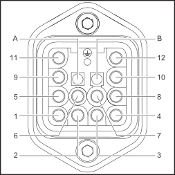
Harting Han12P (X1) connecting plug configuration – cable-side view
- “Cleaning motor on / lifting device up” input signal
- “Spray parting agent” input signal
- GND actuator
- + 24 V DC
- “Upper cleaning motor” output signal
- “Lower cleaning motor” output signal
- Input/output signal actuator/sensor
- Input/output signal actuator/sensor
- “Clamp gas nozzle / Cut wire” input signal
- “Gas nozzle clamped / wire cut” output signal
- “Gas nozzle free / wire cutter open” output signal
- GND sensor
Installation and Startup
Safety
Safety
WARNING!
Danger from incorrect operation and work that is not carried out properly.
This can result in severe personal injury and damage to property.
All the work and functions described in this document must only be carried out by trained and qualified personnel.
Read and understand this document.
Read and understand all the Operating Instructions for the system components, especially the safety rules.
WARNING!
Danger due to machines starting automatically.
This can result in severe personal injury and damage to property.
In addition to these Operating Instructions, observe the safety rules of the robot manufacturer and welding system manufacturer. Before entering the robot work area, ensure that all protective measures in the robot work area are in place and remain in place for the duration of the access.
WARNING!
Danger due to moving mechanical parts, flying debris (chips, etc.), and compressed air/parting agent mixture discharged from the parting-agent injection nozzle.
This can result in severe personal injury and damage to property.
Before carrying out any work, disconnect the compressed air and power supply from the cleaning device and the associated system components and make sure that the compressed air and power supply remain disconnected until all work has been completed.
Before carrying out any work, ensure that the cleaning device is depressurized - the necessary steps for this can be found in the following chapter Ensuring that the cleaning device is depressurized from page (→).
WARNING!
If the cleaning device is supplied with voltage and/or compressed air, there is a risk of serious injury from: rotating cleaning cutter, cleaning motor moving up/down, gas nozzle clamping device moving out/in, activated wire cutter, flying parts (chips, etc.), compressed air/parting agent mixture escaping from the parting-agent injection nozzle.
This can result in severe personal injury and damage to property.
If work is required on the cleaning device while the cleaning device is being supplied with voltage and/or compressed air, take the following safety measures.
Keep your body, especially hands, face and hair, as well as objects and all items of clothing away from the cleaning cutter, cleaning motor, lifting device, gas nozzle clamping device, wire cutter, and parting-agent injection nozzle.
Wear hearing protection.
Wear protective goggles with side protection.
Safety
Safety
WARNING!
Danger from incorrect operation and work that is not carried out properly.
This can result in severe personal injury and damage to property.
All the work and functions described in this document must only be carried out by trained and qualified personnel.
Read and understand this document.
Read and understand all the Operating Instructions for the system components, especially the safety rules.
WARNING!
Danger due to machines starting automatically.
This can result in severe personal injury and damage to property.
In addition to these Operating Instructions, observe the safety rules of the robot manufacturer and welding system manufacturer. Before entering the robot work area, ensure that all protective measures in the robot work area are in place and remain in place for the duration of the access.
WARNING!
Danger due to moving mechanical parts, flying debris (chips, etc.), and compressed air/parting agent mixture discharged from the parting-agent injection nozzle.
This can result in severe personal injury and damage to property.
Before carrying out any work, disconnect the compressed air and power supply from the cleaning device and the associated system components and make sure that the compressed air and power supply remain disconnected until all work has been completed.
Before carrying out any work, ensure that the cleaning device is depressurized - the necessary steps for this can be found in the following chapter Ensuring that the cleaning device is depressurized from page (→).
WARNING!
If the cleaning device is supplied with voltage and/or compressed air, there is a risk of serious injury from: rotating cleaning cutter, cleaning motor moving up/down, gas nozzle clamping device moving out/in, activated wire cutter, flying parts (chips, etc.), compressed air/parting agent mixture escaping from the parting-agent injection nozzle.
This can result in severe personal injury and damage to property.
If work is required on the cleaning device while the cleaning device is being supplied with voltage and/or compressed air, take the following safety measures.
Keep your body, especially hands, face and hair, as well as objects and all items of clothing away from the cleaning cutter, cleaning motor, lifting device, gas nozzle clamping device, wire cutter, and parting-agent injection nozzle.
Wear hearing protection.
Wear protective goggles with side protection.
Safety
WARNING!
Danger from incorrect operation and work that is not carried out properly.
This can result in severe personal injury and damage to property.
All the work and functions described in this document must only be carried out by trained and qualified personnel.
Read and understand this document.
Read and understand all the Operating Instructions for the system components, especially the safety rules.
WARNING!
Danger due to machines starting automatically.
This can result in severe personal injury and damage to property.
In addition to these Operating Instructions, observe the safety rules of the robot manufacturer and welding system manufacturer. Before entering the robot work area, ensure that all protective measures in the robot work area are in place and remain in place for the duration of the access.
WARNING!
Danger due to moving mechanical parts, flying debris (chips, etc.), and compressed air/parting agent mixture discharged from the parting-agent injection nozzle.
This can result in severe personal injury and damage to property.
Before carrying out any work, disconnect the compressed air and power supply from the cleaning device and the associated system components and make sure that the compressed air and power supply remain disconnected until all work has been completed.
Before carrying out any work, ensure that the cleaning device is depressurized - the necessary steps for this can be found in the following chapter Ensuring that the cleaning device is depressurized from page (→).
WARNING!
If the cleaning device is supplied with voltage and/or compressed air, there is a risk of serious injury from: rotating cleaning cutter, cleaning motor moving up/down, gas nozzle clamping device moving out/in, activated wire cutter, flying parts (chips, etc.), compressed air/parting agent mixture escaping from the parting-agent injection nozzle.
This can result in severe personal injury and damage to property.
If work is required on the cleaning device while the cleaning device is being supplied with voltage and/or compressed air, take the following safety measures.
Keep your body, especially hands, face and hair, as well as objects and all items of clothing away from the cleaning cutter, cleaning motor, lifting device, gas nozzle clamping device, wire cutter, and parting-agent injection nozzle.
Wear hearing protection.
Wear protective goggles with side protection.
Ensuring that the cleaning device is depressurized
To ensure that the cleaning device is depressurized, try to briefly activate the cleaning device without the compressed air supply. To do this, proceed as follows:
1Take protective measures:
- The cleaning cutter, lifting device, gas nozzle clamping device, wire cutter, and parting-agent injection nozzle could be activated. Therefore, keep your body, especially hands, face and hair, as well as objects and all items of clothing, away from the aforementioned parts.
- Wear hearing protection.
- Wear protective goggles with side protection.
2Ensure that the cleaning device is disconnected from the compressed air supply.
3Set the “Start cleaning” screw on the cleaning device to position “1” (activated) for max. 2 seconds and then return to the starting position “0” (deactivated).
- If the cleaning device does not respond to the activation of the “Start cleaning” function, the cleaning device is free of compressed air.
- If the cleaning device responds to the activation of the “Start cleaning” function, the cleaning device is still connected to the compressed air supply.
In this case, the cleaning device must be disconnected from the compressed air supply before starting any work. Finally, ensure that the cleaning device is depressurized.
Before installation
Operating personnel, maintenance personnel
WARNING!
Danger due to machines starting automatically.
Could result in serious personal injury and damage to property.
The device must only ever be operated by one person.
During device operation, it is prohibited for any persons to be inside the working area of the device.
The device must only ever be maintained by one person.
When work is taking place on the device, it is prohibited for any other persons to be in the vicinity of the device.
Operating personnel, maintenance personnel
WARNING!
Danger due to machines starting automatically.
Could result in serious personal injury and damage to property.
The device must only ever be operated by one person.
During device operation, it is prohibited for any persons to be inside the working area of the device.
The device must only ever be maintained by one person.
When work is taking place on the device, it is prohibited for any other persons to be in the vicinity of the device.
Setup regulations
- protection against solid foreign bodies larger than Ø 12.5 mm (0.49 in.)
- no protection against penetrating water
The device must not be set up and operated outdoors. The installed electrical components must be protected against direct exposure to moisture.
WARNING!
Danger from devices falling or toppling over.
This can result in serious personal injury and damage to property.
Always screw the cleaning device to the base.
Measures to ensure safe operation of the device when operating personnel are untrained
If untrained operating personnel have access to the device, the compressed air supply to the device must be disconnected for the duration of this access in accordance with “Performance Level d” of ISO 13849-1.
We recommend FESTO’s MS6-SV soft-start and quick exhaust valve for interrupting the compressed air supply as required.
Screwing the Cleaning Device to the Solid Surface
Screwing the cleaning device to the base
WARNING!
Danger from devices falling or toppling over.
This can result in severe personal injury and damage to property.
Always screw the cleaning device to the base.
The supplied mounting material only for bases up to max. 5 mm (0.197 in.) Use material thickness.
For bases with a material thickness greater than 5 mm (0.197 in.), suitable and appropriately dimensioned fastening material must be used.
Install the cleaning device and the mounting bracket on a flat, stable solid surface (base) free of vibration.
IMPORTANT!
Position the cleaning device so that the robot’s approach route to the cleaning position is as short as possible.
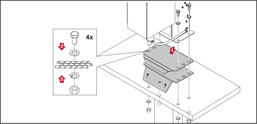
1Place the mounting bracket of the collection container and the cleaning device on the base in the order shown.
2Screw the cleaning device and the mounting bracket of the collection container to the base using the supplied fastening material.
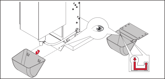
3Hook the collecting vessel from left to right into the mounting bracket of the collecting vessel.
Screwing the cleaning device to the base
WARNING!
Danger from devices falling or toppling over.
This can result in severe personal injury and damage to property.
Always screw the cleaning device to the base.
The supplied mounting material only for bases up to max. 5 mm (0.197 in.) Use material thickness.
For bases with a material thickness greater than 5 mm (0.197 in.), suitable and appropriately dimensioned fastening material must be used.
Install the cleaning device and the mounting bracket on a flat, stable solid surface (base) free of vibration.
IMPORTANT!
Position the cleaning device so that the robot’s approach route to the cleaning position is as short as possible.
1Place the mounting bracket of the collection container and the cleaning device on the base in the order shown.
2Screw the cleaning device and the mounting bracket of the collection container to the base using the supplied fastening material.
3Hook the collecting vessel from left to right into the mounting bracket of the collecting vessel.
Screwing the cleaning device and work stand to the surface
WARNING!
Danger from devices falling or toppling over.
This can result in severe personal injury and damage to property.
Always secure the assembly stand to the base.
Only use screws suitable for the base (not included in the scope of delivery) to fasten the assembly stand.
Always screw the cleaning device to the work stand.
Set up the work stand (available as an option) on a level, solid, and vibration-free base (foundation).
IMPORTANT!
Position the work stand so that the robot’s approach route to the cleaning device on the work stand is as short as possible.
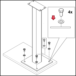
1Screw the assembly stand to the base using suitable fastening material.
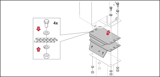
2Place the collecting vessel mounting bracket and the cleaning device on the mounting stand in the order shown.
3Screw down the cleaning device, the mounting bracket of the collection container and the mounting stand with the supplied fastening material.
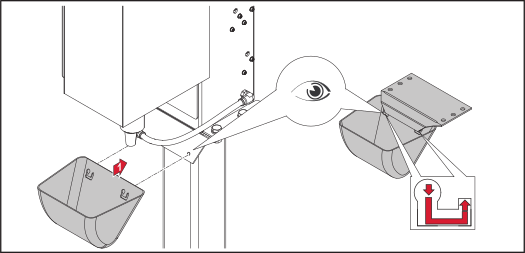
4Hook the collecting vessel from left to right into the mounting bracket of the collecting vessel.
Installing/removing the protective cover
Fitting the protective cover
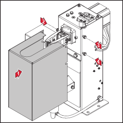
1Place the protective cover on the cleaning device in position.
2Tighten the fastening screws of the protective cover.
Fitting the protective cover
1Place the protective cover on the cleaning device in position.
2Tighten the fastening screws of the protective cover.
Removing the protective cover
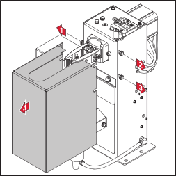
1Loosen the fixing screws of the protective cover.
2Pull the protective cover off the cleaning device towards the front.
Mounting the gas nozzle clamping device
Mounting the gas nozzle clamping device
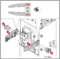
1Only fasten the gas nozzle clamping device to the gas nozzle clamping device holder using the screws supplied (strength class 12.9) and a torque of 11 Nm.
Mounting the gas nozzle clamping device
1Only fasten the gas nozzle clamping device to the gas nozzle clamping device holder using the screws supplied (strength class 12.9) and a torque of 11 Nm.
Welding Torch Cleaning Position
Twin welding torch cleaning position
CAUTION!
Danger due to incorrectly adjusted cleaning position of the welding torch.
The welding torch may be damaged.
Only position the contact tips centrally and vertically over the cleaning motor.
The gas nozzle locking screws are only used for the rough positioning of the contact tip. The gas nozzle locking screw is more or less visible in the bore of the gas nozzle clamping device, depending on the angle of the contact tip.
Before start-up, make sure that the cleaning position is set correctly.
The respective contact tip of the twin welding torch must be positioned centrally and vertically above the cleaning cutter.
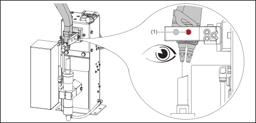
Cleaning position of contact tip 1
1Align the gas nozzle locking screw centrally in the first hole (1) of the clamping device.
2Set the exact position of the cleaning motor according to the chapter Adjusting the Position of the Cleaning Motor on page (→) .
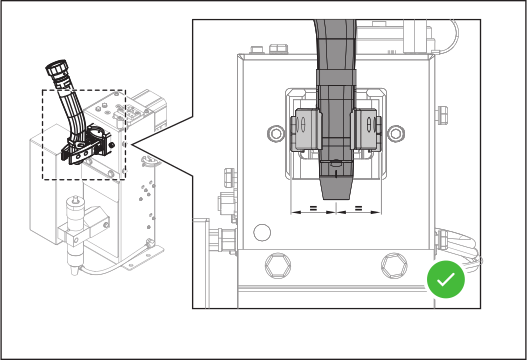
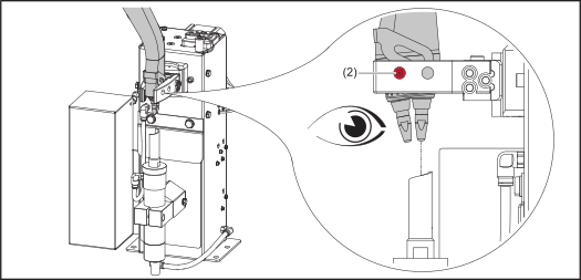
Cleaning position of contact tip 2
1Align the gas nozzle locking screw centrally in the second hole (2) of the clamping device.
2Set the exact position of the cleaning motor according to the chapter Adjusting the Position of the Cleaning Motor on page (→) .
Twin welding torch cleaning position
CAUTION!
Danger due to incorrectly adjusted cleaning position of the welding torch.
The welding torch may be damaged.
Only position the contact tips centrally and vertically over the cleaning motor.
The gas nozzle locking screws are only used for the rough positioning of the contact tip. The gas nozzle locking screw is more or less visible in the bore of the gas nozzle clamping device, depending on the angle of the contact tip.
Before start-up, make sure that the cleaning position is set correctly.
The respective contact tip of the twin welding torch must be positioned centrally and vertically above the cleaning cutter.
Cleaning position of contact tip 1
1Align the gas nozzle locking screw centrally in the first hole (1) of the clamping device.
2Set the exact position of the cleaning motor according to the chapter Adjusting the Position of the Cleaning Motor on page (→) .
Cleaning position of contact tip 2
1Align the gas nozzle locking screw centrally in the second hole (2) of the clamping device.
2Set the exact position of the cleaning motor according to the chapter Adjusting the Position of the Cleaning Motor on page (→) .
Cleaning position of the single welding torch
CAUTION!
Danger due to incorrectly adjusted cleaning position of the welding torch.
The welding torch may be damaged.
Position the contact tip only centrally and vertically above the cleaning motor.
Before start-up, make sure that the cleaning position is set correctly.
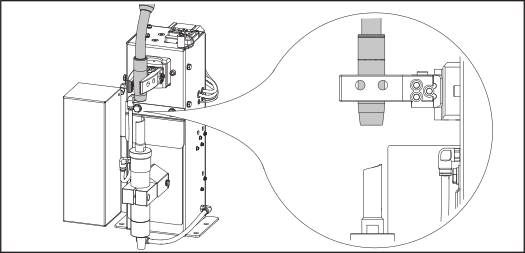
1Position the contact tip of the single welding torch centrally and vertically above the cleaning cutter.
IMPORTANT!
The position of the cleaning motor may only be adjusted for the twin welding torch. If single and twin welding torches are to be cleaned with the Robacta Reamer Single/Twin, the distance to the cleaning cutter and the immersion depth in the contact tip for the respective single welding torch used must be set with the torch position in the clamping device.
IMPORTANT!
The position of the cleaning motor may only be adjusted for the twin welding torch. If single and twin welding torches are to be cleaned with the Robacta Reamer Single/Twin, the distance to the cleaning cutter and the immersion depth in the contact tip for the respective single welding torch used must be set with the torch position in the clamping device.
2Set the exact position of the cleaning motor according to the chapter Setting the position of the cleaning motor for single welding torches on page (→) .
Fitting the Cleaning Cutter
Fitting the cleaning cutter
CAUTION!
Danger due to hot cleaning cutter.
Serious burns may result.
Before handling the cleaning cutter, allow it to cool to room temperature (+25°C, +77°F).
CAUTION!
Danger due to incompatible wearing parts.
Property damage and malfunctions may result.
Only use original Fronius spare parts (contact tips, gas nozzles and cleaning cutters).
IMPORTANT!
No liability is accepted for damage caused by the use of contact tips, gas nozzles, or cleaning cutters from other manufacturers.
1Remove the protective cover from the cleaning device (see chapter Removing the protective cover on page (→)).
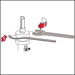
2Insert the supplied clamping key of the cleaning motor into the chuck.
3Tighten the cleaning cutter clockwise using a suitable flat spanner.
4Fit the protective cover to the cleaning device (see chapter Fitting the protective cover on page (→)).
To disassemble the cleaning cutter, follow the steps in reverse order.
Fitting the cleaning cutter
CAUTION!
Danger due to hot cleaning cutter.
Serious burns may result.
Before handling the cleaning cutter, allow it to cool to room temperature (+25°C, +77°F).
CAUTION!
Danger due to incompatible wearing parts.
Property damage and malfunctions may result.
Only use original Fronius spare parts (contact tips, gas nozzles and cleaning cutters).
IMPORTANT!
No liability is accepted for damage caused by the use of contact tips, gas nozzles, or cleaning cutters from other manufacturers.
1Remove the protective cover from the cleaning device (see chapter Removing the protective cover on page (→)).
2Insert the supplied clamping key of the cleaning motor into the chuck.
3Tighten the cleaning cutter clockwise using a suitable flat spanner.
4Fit the protective cover to the cleaning device (see chapter Fitting the protective cover on page (→)).
To disassemble the cleaning cutter, follow the steps in reverse order.
Adjusting the Position of the Cleaning Motor
Setting the position of the cleaning motor for twin welding torches
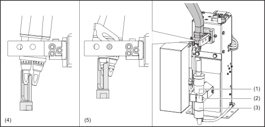
1Remove the protective cover of the clamping device (see chapter Removing the protective cover on page (→)).
2Remove the gas nozzle from the torch body.
3Loosen the fixing screw (2) on the lifting device.
4Make sure that the lifting device (1) is in the bottom-most lift position.
5Move the welding torch into the cleaning position (see chapter Twin welding torch cleaning position on page (→)).
6Manually slide the lifting device (1) to the top-most lift position and hold it in this position.
7Manually slide the cleaning motor (3) with cleaning cutter into the cleaning position.
8Ensure that the cleaning cutter does not touch any components of the welding torch.
- Welding torch with spatter guard, see detail (4).
- Welding torch with insulating sleeve, see detail (5).
9Mount the cleaning motor (3) in this position in the lifting device (1), using the fixing screw (2).
10Perform a function test with the gas nozzle removed. To do this, push the lifting device (1) to the uppermost lifting position by hand.
- The cleaning cutter must surround the contact tip without colliding with it. If the cleaning cutter touches components of the welding torch, the position of the cleaning motor must be adjusted again (from step 3).
11Fit the gas nozzle onto the torch body.
12Perform a function test with the gas nozzle fitted. To do this, push the lifting device (1) to the uppermost lifting position by hand.
- The cleaning cutter must plunge into the gas nozzle without colliding with it. If the cleaning cutter touches components of the welding torch, the position of the cleaning motor must be adjusted again (from step 3).
13Mount the protective cover of the clamping device (see chapter Fitting the protective cover on page (→)).
IMPORTANT!
For twin welding torches, the function test (steps 10 - 12) must be performed individually for each contact tip.
Setting the position of the cleaning motor for twin welding torches
1Remove the protective cover of the clamping device (see chapter Removing the protective cover on page (→)).
2Remove the gas nozzle from the torch body.
3Loosen the fixing screw (2) on the lifting device.
4Make sure that the lifting device (1) is in the bottom-most lift position.
5Move the welding torch into the cleaning position (see chapter Twin welding torch cleaning position on page (→)).
6Manually slide the lifting device (1) to the top-most lift position and hold it in this position.
7Manually slide the cleaning motor (3) with cleaning cutter into the cleaning position.
8Ensure that the cleaning cutter does not touch any components of the welding torch.
- Welding torch with spatter guard, see detail (4).
- Welding torch with insulating sleeve, see detail (5).
9Mount the cleaning motor (3) in this position in the lifting device (1), using the fixing screw (2).
10Perform a function test with the gas nozzle removed. To do this, push the lifting device (1) to the uppermost lifting position by hand.
- The cleaning cutter must surround the contact tip without colliding with it. If the cleaning cutter touches components of the welding torch, the position of the cleaning motor must be adjusted again (from step 3).
11Fit the gas nozzle onto the torch body.
12Perform a function test with the gas nozzle fitted. To do this, push the lifting device (1) to the uppermost lifting position by hand.
- The cleaning cutter must plunge into the gas nozzle without colliding with it. If the cleaning cutter touches components of the welding torch, the position of the cleaning motor must be adjusted again (from step 3).
13Mount the protective cover of the clamping device (see chapter Fitting the protective cover on page (→)).
IMPORTANT!
For twin welding torches, the function test (steps 10 - 12) must be performed individually for each contact tip.
Setting the position of the cleaning motor for single welding torches
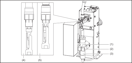
1Remove the protective cover of the clamping device (see chapter Removing the protective cover on page (→)).
2Remove the gas nozzle from the torch body.
3Make sure that the lifting device (1) is in the bottom-most lift position.
4Move the welding torch into the cleaning position (see chapter Cleaning position of the single welding torch on page (→)).
5Manually slide the lifting device (1) to the top-most lift position and hold it in this position.
6Manually slide the cleaning motor (3) with cleaning cutter into the cleaning position.
7Ensure that the cleaning cutter does not touch any components of the welding torch.
- Welding torch with spatter guard, see detail (4).
- Welding torch with insulating sleeve, see detail (5).
8Perform a function test with the gas nozzle removed. To do this, push the lifting device (1) to the uppermost lifting position by hand.
- The cleaning cutter must surround the contact tip without colliding with it. If the cleaning cutter touches components of the welding torch, the position of the welding torch must be adjusted again (step 4).
9Fit the gas nozzle onto the torch body.
10Perform a function test with the gas nozzle fitted. To do this, push the lifting device (1) to the uppermost lifting position by hand.
- The cleaning cutter must plunge into the gas nozzle without colliding with it. If the cleaning cutter touches components of the welding torch, the position of the welding torch must be adjusted again (step 4).
11Mount the protective cover of the clamping device (see chapter Fitting the protective cover on page (→)).
Compressed air supply
Specifications for the compressed air supply
- Set up a compressed air supply using the pressure relief valve and compressed air filter
- Guarantee the compressed air quality in accordance with ISO 8573-1:2001, class 7 4 3, instrument air
- Solid particle concentration £ 10 mg/m3
- Pressure dew point steam £ + 3 °C
- Oil concentration £ 1 mg/m3
Specifications for the compressed air supply
- Set up a compressed air supply using the pressure relief valve and compressed air filter
- Guarantee the compressed air quality in accordance with ISO 8573-1:2001, class 7 4 3, instrument air
- Solid particle concentration £ 10 mg/m3
- Pressure dew point steam £ + 3 °C
- Oil concentration £ 1 mg/m3
Mounting the compressed air relief valve
WARNING!
Danger due to mechanically moving parts.
This can result in severe personal injury and damage to property.
The torch neck changeover station must not be supplied with compressed air until the installation has been completed.
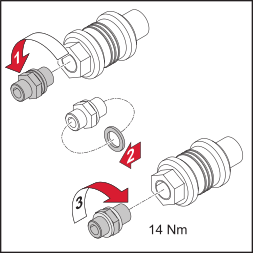
1Unscrew the connection piece from the compressed air relief valve.
2Slide the outer of the two sealing rings onto the opposite side of the connection piece.
3Fasten the connection piece to the compressed air relief valve with a torque of 14 Nm.
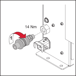
1Attach the compressed air relief valve to the compressed air connection of the cleaning device using the connection piece and a torque of 14 Nm.
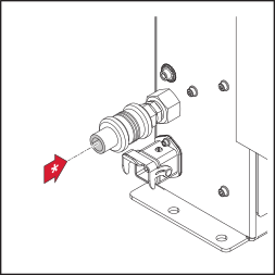
| * | Attach the compressed air supply line to the compressed air relief valve. Thread identification Compressed air connection: G ¼” |
Operation of the compressed air relief valve
You can interrupt and restore the compressed air supply to the cleaning device by moving the compressed air relief valve back and forth.
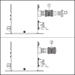
| (1) | Cleaning device is supplied with compressed air. |
| (2) | Compressed air supply to the cleaning device is interrupted. The cleaning device is free of compressed air. |
Starting Up the Parting Agent Atomizer
Filling the parting agent container (1 liter) and connecting it to the cleaning device
1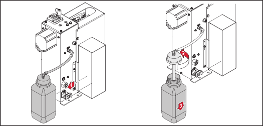
2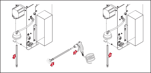
IMPORTANT!
Only use the water-based “Robacta Reamer” parting agent (item number 42.0411.8042) provided by the manufacturer. Its composition is specifically tailored for use with the cleaning device. Correct operation is not ensured when other products are used.
3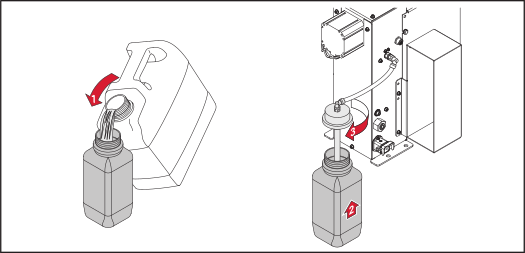
4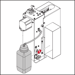
Filling the parting agent container (1 liter) and connecting it to the cleaning device
1
2
IMPORTANT!
Only use the water-based “Robacta Reamer” parting agent (item number 42.0411.8042) provided by the manufacturer. Its composition is specifically tailored for use with the cleaning device. Correct operation is not ensured when other products are used.
3
4
Connecting the parting agent container (10 liter) to the cleaning device
1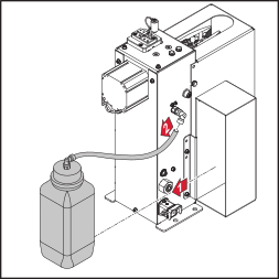
Remove the parting agent container (1 liter) from the cleaning device and terminate the parting agent hose.
IMPORTANT!
The parting agent hose must not be extended. For proper operation, use only original parting agent hoses.
IMPORTANT!
Only use the water-based “Robacta Reamer” parting agent (item number 42.0411.8042) provided by the manufacturer. Its composition is specifically tailored for use with the cleaning device. Correct operation is not ensured when other products are used.
2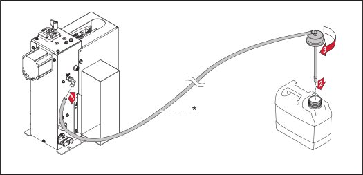
* “Long parting agent hose” option (item number 42.0300.3007)
Connect the release agent hose to the cleaning device and fasten the cap of the parting agent container.
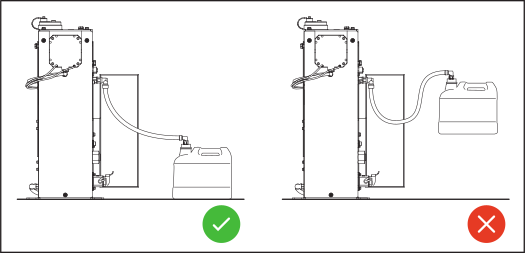
Positioning of the parting agent container (10 liters)
IMPORTANT!
For proper functioning of the injection device, observe the following information on positioning the parting agent container.
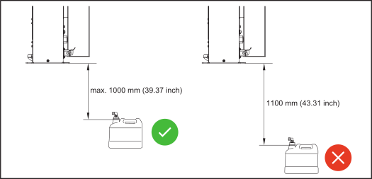
OPT/i TSS TCP Touch Sense
Mount OPT/i TSS TCP Touch Sense
NOTE!
Ensure proper routing and connection of the ground cable. Damage to the ground cable of the OPT/i TSS TCP Touch Sense option can impair its function.
Lay the ground cable in the cable guide on the underside of the OPT/i TSS TCP Touch Sense option.
Do not crush the ground cable or damage the insulation.
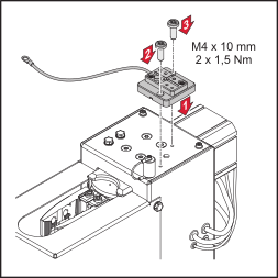
1Position the OPT/i TSS TCP Touch Sense option on top of the Robacta Reamer Single/Twin.
2Insert the 2 screws supplied (M4 x 10 mm) into the hole and fasten with a torque of 1.5 Nm.
IMPORTANT!
For the function of the OPT/i TSS TCP Touch Sense option, a ground earth connection to the workpiece is required.
Mount OPT/i TSS TCP Touch Sense
NOTE!
Ensure proper routing and connection of the ground cable. Damage to the ground cable of the OPT/i TSS TCP Touch Sense option can impair its function.
Lay the ground cable in the cable guide on the underside of the OPT/i TSS TCP Touch Sense option.
Do not crush the ground cable or damage the insulation.
1Position the OPT/i TSS TCP Touch Sense option on top of the Robacta Reamer Single/Twin.
2Insert the 2 screws supplied (M4 x 10 mm) into the hole and fasten with a torque of 1.5 Nm.
IMPORTANT!
For the function of the OPT/i TSS TCP Touch Sense option, a ground earth connection to the workpiece is required.
Manually Checking the Cleaning Device Functions
Safety
WARNING!
For the following tasks, the cleaning device must be supplied with compressed air. This results in danger from the rotating cleaning cutter, cleaning motor moving up/down, gas nozzle clamping device moving out/in, flying parts (chips, etc.), compressed air/parting agent mixture escaping from the parting-agent injection nozzle.
This can result in severe personal injury and damage to property.
Keep your body, especially hands, face and hair, as well as objects and all items of clothing away from the cleaning cutter, cleaning motor, lifting device, gas nozzle clamping device, wire cutter, and parting-agent injection nozzle.
Wear hearing protection.
Wear protective goggles with side protection.
Safety
WARNING!
For the following tasks, the cleaning device must be supplied with compressed air. This results in danger from the rotating cleaning cutter, cleaning motor moving up/down, gas nozzle clamping device moving out/in, flying parts (chips, etc.), compressed air/parting agent mixture escaping from the parting-agent injection nozzle.
This can result in severe personal injury and damage to property.
Keep your body, especially hands, face and hair, as well as objects and all items of clothing away from the cleaning cutter, cleaning motor, lifting device, gas nozzle clamping device, wire cutter, and parting-agent injection nozzle.
Wear hearing protection.
Wear protective goggles with side protection.
Manually checking the cleaning device functions
- 0 = disabled
- 1 = activated
Before manually checking the individual functions, the following activities must be performed:
1Move the welding torch into the cleaning position (see chapter Welding Torch Cleaning Position on page (→)).
2Establish the compressed air supply for the cleaning device (see chapter Compressed air supply on page (→)).
3Clamp the gas nozzle in the clamping device.
“Cut wire” function
1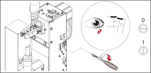
2Activate the function with the set screw and a 90° clockwise turn.
3After the function has been completed, check whether the welding wire has been cut to the correct length.
“Clamp gas nozzle” function
1
2Activate the function with the set screw and a 90° clockwise turn.
3Check that the gas nozzle is correctly held in the clamping device.
“Cleaning motor on / lifting device up” function
1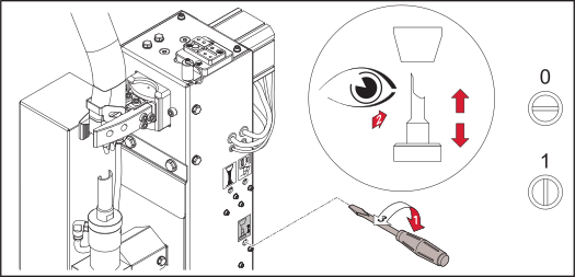
2Activate the function with the set screw and a 90° clockwise turn.
3Check the function of the clamping device for the gas nozzle.
4Check the insertion depth of the cleaning cutter into the gas nozzle.
5Check the function of the cleaning motor.
“Spray parting agent” function
1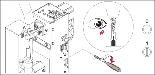
2Activate the function with the set screw and a 90° clockwise turn.
3After the function has been completed, check whether the gas nozzle is moistened with parting agent.
IMPORTANT!
The quantity of parting agent is controlled by the injection time (see chapter Program sequence from page (→)).
Start up the Cleaning Device
Requirements for commissioning
- Cleaning device screwed to the base (see chapter Screwing the Cleaning Device to the Solid Surface on page (→)).
- Clamping device gas nozzle mounted (see chapter Mounting the gas nozzle clamping device on page (→)).
- Cleaning cutter mounted (see chapter Fitting the Cleaning Cutter on page (→)).
- Position of the cleaning motor set (see chapter Adjusting the Position of the Cleaning Motor on page (→)).
- Parting agent atomizer put into operation (see chapter Starting Up the Parting Agent Atomizer on page (→)).
- Compressed air supply established (see chapter Compressed air supply on page (→)).
- Functions checked manually (see chapter Manually Checking the Cleaning Device Functions on page (→)).
- Cleaning device connected to the robot control unit.
- All covers installed and all safety devices in good order and installed in the location intended (see chapter Fitting the protective cover on page (→)).
Requirements for commissioning
- Cleaning device screwed to the base (see chapter Screwing the Cleaning Device to the Solid Surface on page (→)).
- Clamping device gas nozzle mounted (see chapter Mounting the gas nozzle clamping device on page (→)).
- Cleaning cutter mounted (see chapter Fitting the Cleaning Cutter on page (→)).
- Position of the cleaning motor set (see chapter Adjusting the Position of the Cleaning Motor on page (→)).
- Parting agent atomizer put into operation (see chapter Starting Up the Parting Agent Atomizer on page (→)).
- Compressed air supply established (see chapter Compressed air supply on page (→)).
- Functions checked manually (see chapter Manually Checking the Cleaning Device Functions on page (→)).
- Cleaning device connected to the robot control unit.
- All covers installed and all safety devices in good order and installed in the location intended (see chapter Fitting the protective cover on page (→)).
Commissioning
An active signal from the robot control starts up the cleaning device.
Program sequence
Safety
CAUTION!
Danger due to improper installation and commissioning.
This can result in damage to property.
The cleaning device’s functions must be manually checked before starting automatic operation.
Only start automatic mode once the cleaning device has been installed and commissioned properly.
NOTE!
If wetting agent has not been applied to the inside of the welding torch, this may lead to the permanent contamination of the welding torch when welding begins.
Always wet the inside of the welding torch with the manufacturer’s parting agent before starting automatic mode.
Safety
CAUTION!
Danger due to improper installation and commissioning.
This can result in damage to property.
The cleaning device’s functions must be manually checked before starting automatic operation.
Only start automatic mode once the cleaning device has been installed and commissioned properly.
NOTE!
If wetting agent has not been applied to the inside of the welding torch, this may lead to the permanent contamination of the welding torch when welding begins.
Always wet the inside of the welding torch with the manufacturer’s parting agent before starting automatic mode.
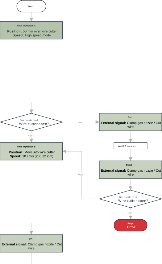
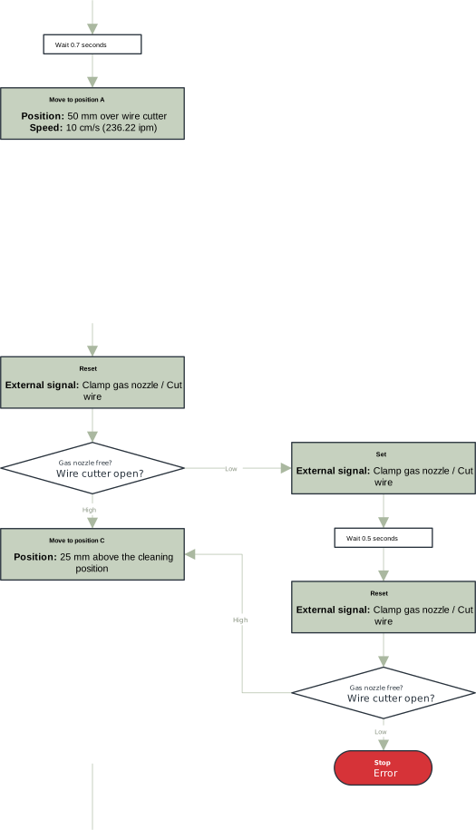
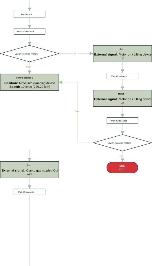
Cleaning program sequence for twin welding torches
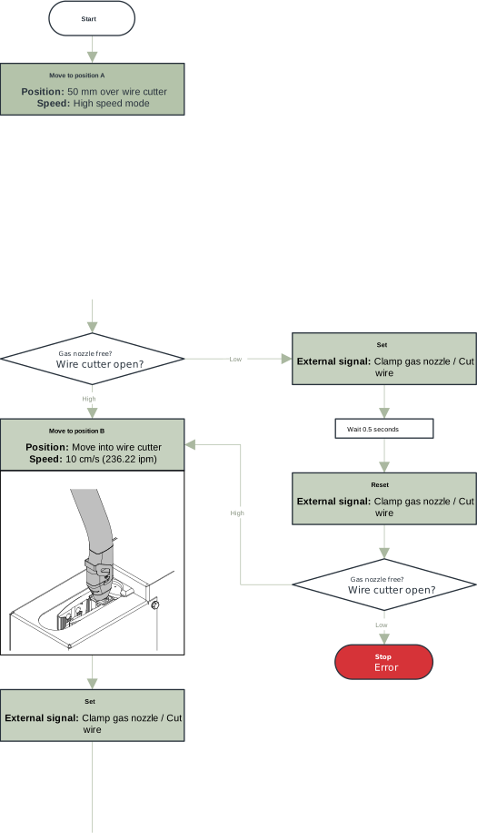
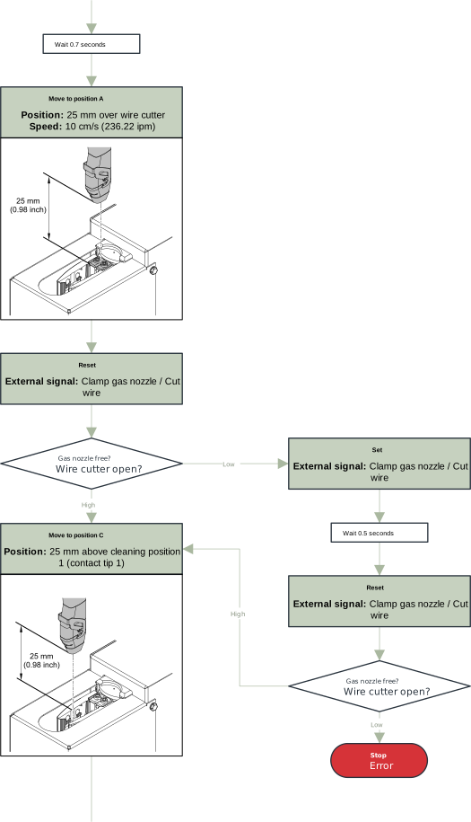
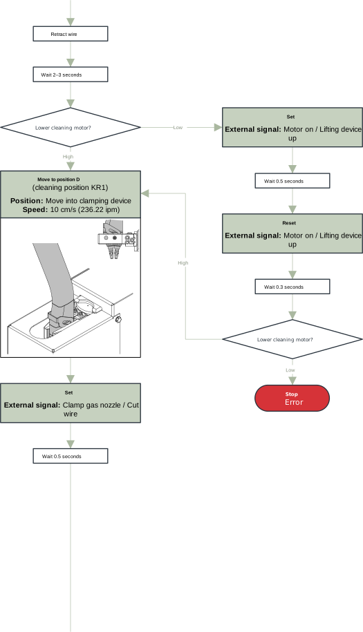
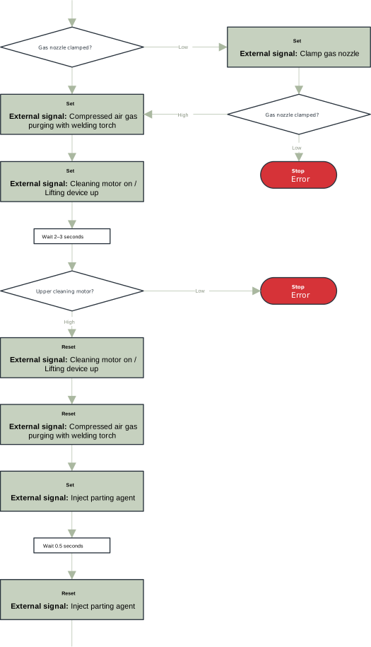
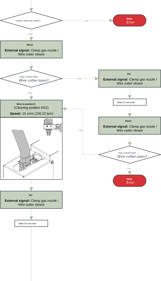
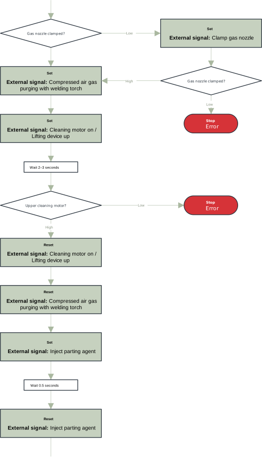
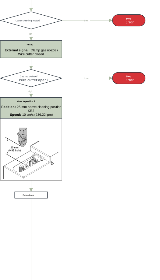
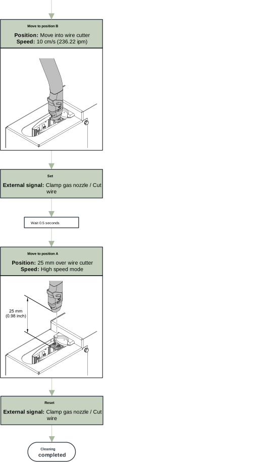
Program sequence of cleaning for single welding torches
If the diameter of the gas nozzle is too small, the gas nozzle may not be clamped properly in the clamping device. No signal is output that the clamping device is closed.
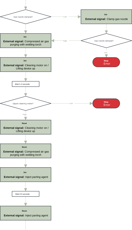
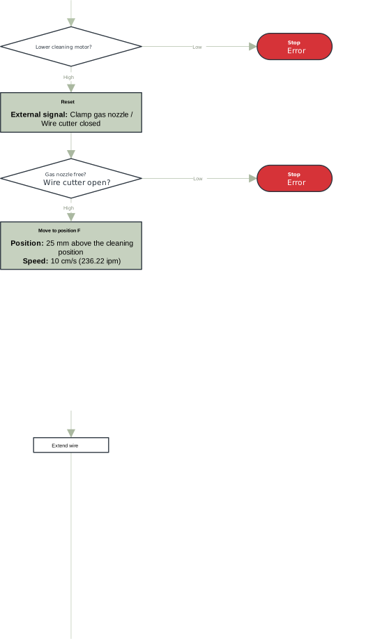
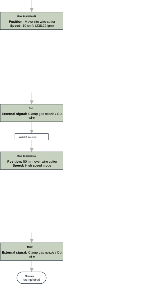
Cleaning signal sequence
Signal input
Cleaning motor on / lifting device up signal:
= Pin 1 at the Harting Han12P connecting plug (X1)

Contact tip 1

Contact tip 2
Spray in parting agent signal:
= Pin 2 on the Harting Han12P connecting plug (X1)

Contact tip 1

Contact tip 2
Clamp gas nozzle / cut wire signal:
= Pin 9 on Harting Han12P connector (X1)

Signal input
Cleaning motor on / lifting device up signal:
= Pin 1 at the Harting Han12P connecting plug (X1)
Contact tip 1
Contact tip 2
Spray in parting agent signal:
= Pin 2 on the Harting Han12P connecting plug (X1)
Contact tip 1
Contact tip 2
Clamp gas nozzle / cut wire signal:
= Pin 9 on Harting Han12P connector (X1)
Signal input and output
Actuator/sensor signal (Pin 7):
= Pin 7 on the Harting Han12P connecting plug (X1)

Actuator/sensor signal (Pin 8):
= Pin 8 on the Harting Han12P connecting plug (X1)

Signal output
Upper cleaning motor signal:
= Pin 5 at the Harting Han12P connecting plug (X1)

Lower cleaning motor signal:
= Pin 6 at the Harting Han12P connecting plug (X1)

Gas nozzle free signal:
= Pin 11 on the Harting Han12P connecting plug (X1)

Gas nozzle clamped / wire cutter closed signal:
= Pin 10 at Harting Han12P connecting plug (X1)

Service, maintenance and disposal
Safety
Safety
WARNING!
Danger from incorrect operation and work that is not carried out properly.
This can result in severe personal injury and damage to property.
All the work and functions described in this document must only be carried out by trained and qualified personnel.
Read and understand this document.
Read and understand all the Operating Instructions for the system components, especially the safety rules.
WARNING!
Danger due to machines starting automatically.
This can result in severe personal injury and damage to property.
In addition to these Operating Instructions, observe the safety rules of the robot manufacturer and welding system manufacturer. Before entering the robot work area, ensure that all protective measures in the robot work area are in place and remain in place for the duration of the access.
WARNING!
Danger due to moving mechanical parts, flying debris (chips, etc.), and compressed air/parting agent mixture discharged from the parting-agent injection nozzle.
This can result in severe personal injury and damage to property.
Before carrying out any work, disconnect the compressed air and power supply from the cleaning device and the associated system components and make sure that the compressed air and power supply remain disconnected until all work has been completed.
Before carrying out any work, ensure that the cleaning device is depressurized - the necessary steps for this can be found in the following chapter Ensuring that the cleaning device is depressurized from page (→).
WARNING!
If the cleaning device is supplied with voltage and/or compressed air, there is a risk of serious injury from: rotating cleaning cutter, cleaning motor moving up/down, gas nozzle clamping device moving out/in, activated wire cutter, flying parts (chips, etc.), compressed air/parting agent mixture escaping from the parting-agent injection nozzle.
This can result in severe personal injury and damage to property.
If work is required on the cleaning device while the cleaning device is being supplied with voltage and/or compressed air, take the following safety measures.
Keep your body, especially hands, face and hair, as well as objects and all items of clothing away from the cleaning cutter, cleaning motor, lifting device, gas nozzle clamping device, wire cutter, and parting-agent injection nozzle.
Wear hearing protection.
Wear protective goggles with side protection.
Safety
Safety
WARNING!
Danger from incorrect operation and work that is not carried out properly.
This can result in severe personal injury and damage to property.
All the work and functions described in this document must only be carried out by trained and qualified personnel.
Read and understand this document.
Read and understand all the Operating Instructions for the system components, especially the safety rules.
WARNING!
Danger due to machines starting automatically.
This can result in severe personal injury and damage to property.
In addition to these Operating Instructions, observe the safety rules of the robot manufacturer and welding system manufacturer. Before entering the robot work area, ensure that all protective measures in the robot work area are in place and remain in place for the duration of the access.
WARNING!
Danger due to moving mechanical parts, flying debris (chips, etc.), and compressed air/parting agent mixture discharged from the parting-agent injection nozzle.
This can result in severe personal injury and damage to property.
Before carrying out any work, disconnect the compressed air and power supply from the cleaning device and the associated system components and make sure that the compressed air and power supply remain disconnected until all work has been completed.
Before carrying out any work, ensure that the cleaning device is depressurized - the necessary steps for this can be found in the following chapter Ensuring that the cleaning device is depressurized from page (→).
WARNING!
If the cleaning device is supplied with voltage and/or compressed air, there is a risk of serious injury from: rotating cleaning cutter, cleaning motor moving up/down, gas nozzle clamping device moving out/in, activated wire cutter, flying parts (chips, etc.), compressed air/parting agent mixture escaping from the parting-agent injection nozzle.
This can result in severe personal injury and damage to property.
If work is required on the cleaning device while the cleaning device is being supplied with voltage and/or compressed air, take the following safety measures.
Keep your body, especially hands, face and hair, as well as objects and all items of clothing away from the cleaning cutter, cleaning motor, lifting device, gas nozzle clamping device, wire cutter, and parting-agent injection nozzle.
Wear hearing protection.
Wear protective goggles with side protection.
Safety
WARNING!
Danger from incorrect operation and work that is not carried out properly.
This can result in severe personal injury and damage to property.
All the work and functions described in this document must only be carried out by trained and qualified personnel.
Read and understand this document.
Read and understand all the Operating Instructions for the system components, especially the safety rules.
WARNING!
Danger due to machines starting automatically.
This can result in severe personal injury and damage to property.
In addition to these Operating Instructions, observe the safety rules of the robot manufacturer and welding system manufacturer. Before entering the robot work area, ensure that all protective measures in the robot work area are in place and remain in place for the duration of the access.
WARNING!
Danger due to moving mechanical parts, flying debris (chips, etc.), and compressed air/parting agent mixture discharged from the parting-agent injection nozzle.
This can result in severe personal injury and damage to property.
Before carrying out any work, disconnect the compressed air and power supply from the cleaning device and the associated system components and make sure that the compressed air and power supply remain disconnected until all work has been completed.
Before carrying out any work, ensure that the cleaning device is depressurized - the necessary steps for this can be found in the following chapter Ensuring that the cleaning device is depressurized from page (→).
WARNING!
If the cleaning device is supplied with voltage and/or compressed air, there is a risk of serious injury from: rotating cleaning cutter, cleaning motor moving up/down, gas nozzle clamping device moving out/in, activated wire cutter, flying parts (chips, etc.), compressed air/parting agent mixture escaping from the parting-agent injection nozzle.
This can result in severe personal injury and damage to property.
If work is required on the cleaning device while the cleaning device is being supplied with voltage and/or compressed air, take the following safety measures.
Keep your body, especially hands, face and hair, as well as objects and all items of clothing away from the cleaning cutter, cleaning motor, lifting device, gas nozzle clamping device, wire cutter, and parting-agent injection nozzle.
Wear hearing protection.
Wear protective goggles with side protection.
Ensuring that the cleaning device is depressurized
To ensure that the cleaning device is depressurized, try to briefly activate the cleaning device without the compressed air supply. To do this, proceed as follows:
1Take protective measures:
- The cleaning cutter, lifting device, gas nozzle clamping device, wire cutter, and parting-agent injection nozzle could be activated. Therefore, keep your body, especially hands, face and hair, as well as objects and all items of clothing, away from the aforementioned parts.
- Wear hearing protection.
- Wear protective goggles with side protection.
2Ensure that the cleaning device is disconnected from the compressed air supply.
3Set the “Start cleaning” screw on the cleaning device to position “1” (activated) for max. 2 seconds and then return to the starting position “0” (deactivated).
- If the cleaning device does not respond to the activation of the “Start cleaning” function, the cleaning device is free of compressed air.
- If the cleaning device responds to the activation of the “Start cleaning” function, the cleaning device is still connected to the compressed air supply.
In this case, the cleaning device must be disconnected from the compressed air supply before starting any work. Finally, ensure that the cleaning device is depressurized.
Service, maintenance and disposal
Before every start-up
- Check the fill level in the parting agent container and top up if necessary.
- Check for wear of the cleaning cutter and replace the cleaning cutter if necessary.
- Drain the cleaning device’s collecting container.
- In general, you should visually inspect the cleaning device and ensure that any damage is repaired immediately (before commissioning).
Before every start-up
- Check the fill level in the parting agent container and top up if necessary.
- Check for wear of the cleaning cutter and replace the cleaning cutter if necessary.
- Drain the cleaning device’s collecting container.
- In general, you should visually inspect the cleaning device and ensure that any damage is repaired immediately (before commissioning).
Daily
CAUTION!
Danger due to cleaning agents containing solvents.
This can result in damage to property.
Only clean the cleaning device with cleaning products that are free of solvents.
1Remove deposited parting agent and contamination from the device.
Weekly
CAUTION!
Danger due to cleaning agents containing solvents.
This can result in damage to property.
Only clean the parting agent container with cleaning products that are free of solvents.
1Check the parting agent container for contamination and clean if necessary.
2Blow out the intake filter in the parting agent container from the inside out with compressed air using the intake hose (see chapter Starting Up the Parting Agent Atomizer from page (→)).
Every 6 months
1Open the device and check the pneumatic valves to ensure:
- no leaks
- all screws are screwed tightly in place
- all screw joints are fixed firmly in place on the pneumatic valves.
Whenever required:
Open the device and
1blast the inside of the device clean with dry and reduced compressed air
2lightly oil the guides on the lifting device’s lifting cylinder
3restore the operational state of the device.
Disposal
Disposal must only be carried out in accordance with the section of the same name in the "Safety rules" chapter.
Troubleshooting
Safety
Safety
WARNING!
Danger from incorrect operation and work that is not carried out properly.
This can result in severe personal injury and damage to property.
All the work and functions described in this document must only be carried out by trained and qualified personnel.
Read and understand this document.
Read and understand all the Operating Instructions for the system components, especially the safety rules.
WARNING!
Danger due to machines starting automatically.
This can result in severe personal injury and damage to property.
In addition to these Operating Instructions, observe the safety rules of the robot manufacturer and welding system manufacturer. Before entering the robot work area, ensure that all protective measures in the robot work area are in place and remain in place for the duration of the access.
WARNING!
Danger due to moving mechanical parts, flying debris (chips, etc.), and compressed air/parting agent mixture discharged from the parting-agent injection nozzle.
This can result in severe personal injury and damage to property.
Before carrying out any work, disconnect the compressed air and power supply from the cleaning device and the associated system components and make sure that the compressed air and power supply remain disconnected until all work has been completed.
Before carrying out any work, ensure that the cleaning device is depressurized - the necessary steps for this can be found in the following chapter Ensuring that the cleaning device is depressurized from page (→).
WARNING!
If the cleaning device is supplied with voltage and/or compressed air, there is a risk of serious injury from: rotating cleaning cutter, cleaning motor moving up/down, gas nozzle clamping device moving out/in, activated wire cutter, flying parts (chips, etc.), compressed air/parting agent mixture escaping from the parting-agent injection nozzle.
This can result in severe personal injury and damage to property.
If work is required on the cleaning device while the cleaning device is being supplied with voltage and/or compressed air, take the following safety measures.
Keep your body, especially hands, face and hair, as well as objects and all items of clothing away from the cleaning cutter, cleaning motor, lifting device, gas nozzle clamping device, wire cutter, and parting-agent injection nozzle.
Wear hearing protection.
Wear protective goggles with side protection.
Safety
Safety
WARNING!
Danger from incorrect operation and work that is not carried out properly.
This can result in severe personal injury and damage to property.
All the work and functions described in this document must only be carried out by trained and qualified personnel.
Read and understand this document.
Read and understand all the Operating Instructions for the system components, especially the safety rules.
WARNING!
Danger due to machines starting automatically.
This can result in severe personal injury and damage to property.
In addition to these Operating Instructions, observe the safety rules of the robot manufacturer and welding system manufacturer. Before entering the robot work area, ensure that all protective measures in the robot work area are in place and remain in place for the duration of the access.
WARNING!
Danger due to moving mechanical parts, flying debris (chips, etc.), and compressed air/parting agent mixture discharged from the parting-agent injection nozzle.
This can result in severe personal injury and damage to property.
Before carrying out any work, disconnect the compressed air and power supply from the cleaning device and the associated system components and make sure that the compressed air and power supply remain disconnected until all work has been completed.
Before carrying out any work, ensure that the cleaning device is depressurized - the necessary steps for this can be found in the following chapter Ensuring that the cleaning device is depressurized from page (→).
WARNING!
If the cleaning device is supplied with voltage and/or compressed air, there is a risk of serious injury from: rotating cleaning cutter, cleaning motor moving up/down, gas nozzle clamping device moving out/in, activated wire cutter, flying parts (chips, etc.), compressed air/parting agent mixture escaping from the parting-agent injection nozzle.
This can result in severe personal injury and damage to property.
If work is required on the cleaning device while the cleaning device is being supplied with voltage and/or compressed air, take the following safety measures.
Keep your body, especially hands, face and hair, as well as objects and all items of clothing away from the cleaning cutter, cleaning motor, lifting device, gas nozzle clamping device, wire cutter, and parting-agent injection nozzle.
Wear hearing protection.
Wear protective goggles with side protection.
Safety
WARNING!
Danger from incorrect operation and work that is not carried out properly.
This can result in severe personal injury and damage to property.
All the work and functions described in this document must only be carried out by trained and qualified personnel.
Read and understand this document.
Read and understand all the Operating Instructions for the system components, especially the safety rules.
WARNING!
Danger due to machines starting automatically.
This can result in severe personal injury and damage to property.
In addition to these Operating Instructions, observe the safety rules of the robot manufacturer and welding system manufacturer. Before entering the robot work area, ensure that all protective measures in the robot work area are in place and remain in place for the duration of the access.
WARNING!
Danger due to moving mechanical parts, flying debris (chips, etc.), and compressed air/parting agent mixture discharged from the parting-agent injection nozzle.
This can result in severe personal injury and damage to property.
Before carrying out any work, disconnect the compressed air and power supply from the cleaning device and the associated system components and make sure that the compressed air and power supply remain disconnected until all work has been completed.
Before carrying out any work, ensure that the cleaning device is depressurized - the necessary steps for this can be found in the following chapter Ensuring that the cleaning device is depressurized from page (→).
WARNING!
If the cleaning device is supplied with voltage and/or compressed air, there is a risk of serious injury from: rotating cleaning cutter, cleaning motor moving up/down, gas nozzle clamping device moving out/in, activated wire cutter, flying parts (chips, etc.), compressed air/parting agent mixture escaping from the parting-agent injection nozzle.
This can result in severe personal injury and damage to property.
If work is required on the cleaning device while the cleaning device is being supplied with voltage and/or compressed air, take the following safety measures.
Keep your body, especially hands, face and hair, as well as objects and all items of clothing away from the cleaning cutter, cleaning motor, lifting device, gas nozzle clamping device, wire cutter, and parting-agent injection nozzle.
Wear hearing protection.
Wear protective goggles with side protection.
Ensuring that the cleaning device is depressurized
To ensure that the cleaning device is depressurized, try to briefly activate the cleaning device without the compressed air supply. To do this, proceed as follows:
1Take protective measures:
- The cleaning cutter, lifting device, gas nozzle clamping device, wire cutter, and parting-agent injection nozzle could be activated. Therefore, keep your body, especially hands, face and hair, as well as objects and all items of clothing, away from the aforementioned parts.
- Wear hearing protection.
- Wear protective goggles with side protection.
2Ensure that the cleaning device is disconnected from the compressed air supply.
3Set the “Start cleaning” screw on the cleaning device to position “1” (activated) for max. 2 seconds and then return to the starting position “0” (deactivated).
- If the cleaning device does not respond to the activation of the “Start cleaning” function, the cleaning device is free of compressed air.
- If the cleaning device responds to the activation of the “Start cleaning” function, the cleaning device is still connected to the compressed air supply.
In this case, the cleaning device must be disconnected from the compressed air supply before starting any work. Finally, ensure that the cleaning device is depressurized.
Troubleshooting
Errors in the Program Sequence
Errors in the Program Sequence
Parting agent is not injected
Parting agent container is full
| Cause: | Injection quantity too low. |
| Remedy: | Extend the injection time. |
| Cause: | The intake filter of the parting agent hose in the parting agent container is contaminated. |
| Remedy: | Clean the suction filter of the parting agent hose with compressed air (for more information, see chapter Starting Up the Parting Agent Atomizer from page (→)). |
| Cause: | No signal from robot. |
| Remedy: | Check robot program. |
| Cause: | Parting-agent injection nozzle blocked. |
| Remedy: | Clean the parting-agent injection nozzle. Notify the service team (have parting-agent injection nozzle replaced). |
| Cause: | Vacuum pump defective. |
| Remedy: | Contact service team (have vacuum pump replaced). |
| Cause: | Solenoid valve has mechanical fault. |
| Remedy: | Contact service team (have solenoid valve replaced). |
Welding torch has been poorly cleaned or is damaged
| Cause: | Position of the cleaning motor incorrectly set. |
| Remedy: | Set the position of the cleaning motor correctly (see chapterAdjusting the Position of the Cleaning Motor from page (→)). |
| Cause: | Cleaning position of the welding torch incorrectly set. |
| Remedy: | Set the cleaning position of the welding torch again (see chapter Welding Torch Cleaning Position from page (→)). |
| Cause: | Cleaning cutter does not fit the welding torch geometry. |
| Remedy: | Fit a correct cleaning cutter. |
| Cause: | Cleaning cutter worn. |
| Remedy: | Replace cleaning cutter. |
Lifting device does not move up or down
| Cause: | Compressed air supply missing. |
| Remedy: | Set up the compressed air supply. |
| Cause: | No signal from robot. |
| Remedy: | Check robot program. |
| Cause: | Solenoid valve has mechanical fault. |
| Remedy: | Contact service team (have solenoid valve replaced). |
| Cause: | Throttle valve cannot be adjusted or is faulty. |
| Remedy: | Contact service team (have throttle valve replaced). |
| Cause: | Seal on lifting cylinder is faulty. |
| Remedy: | Contact service team (have lifting cylinder replaced). |
Cleaning motor not working
| Cause: | Compressed air supply missing. |
| Remedy: | Set up the compressed air supply. |
| Cause: | No signal from robot. |
| Remedy: | Check robot program. |
| Cause: | Cleaning motor has mechanical fault. |
| Remedy: | Contact service team (have cleaning motor replaced). |
| Cause: | Solenoid valve has mechanical fault. |
| Remedy: | Contact service team (have solenoid valve replaced). |
Technical data
Technical data
Robacta Reamer Single/Twin
Supply voltage | + 24 V DC |
Nominal output | 2.4 W |
Nominal pressure | 6 bar |
Air consumption | 420 l/min |
Thread identification for compressed air connection | G ¼” |
Standard I/O (X1) | Input: + 24 V DC/max. 100 mA |
Cleaning time | 4.5 - 6.5 s |
Overall cycle time | 5.0 - 9.0 s |
Capacity of the parting agent container | 1 l |
Protection class | Protection class 21 |
Mark of conformity | CE, UKCA |
Safety symbols | S |
“Performance Level” | c |
Maximum noise emission (LWA) | 82 dB (A) |
EMC emission class | A1) |
Dimensions l x w x h | 345 x 245 x 400 mm |
Weight | 14.5 kg |
1) A device in emissions class A is not intended for use in residential areas in which the electrical power is supplied via a public low-voltage grid. The electromagnetic compatibility may be influenced by conducted or radiated radio frequencies.
Technical data
Robacta Reamer Single/Twin
Supply voltage | + 24 V DC |
Nominal output | 2.4 W |
Nominal pressure | 6 bar |
Air consumption | 420 l/min |
Thread identification for compressed air connection | G ¼” |
Standard I/O (X1) | Input: + 24 V DC/max. 100 mA |
Cleaning time | 4.5 - 6.5 s |
Overall cycle time | 5.0 - 9.0 s |
Capacity of the parting agent container | 1 l |
Protection class | Protection class 21 |
Mark of conformity | CE, UKCA |
Safety symbols | S |
“Performance Level” | c |
Maximum noise emission (LWA) | 82 dB (A) |
EMC emission class | A1) |
Dimensions l x w x h | 345 x 245 x 400 mm |
Weight | 14.5 kg |
1) A device in emissions class A is not intended for use in residential areas in which the electrical power is supplied via a public low-voltage grid. The electromagnetic compatibility may be influenced by conducted or radiated radio frequencies.
Robacta Reamer Single/Twin
Supply voltage | + 24 V DC |
Nominal output | 2.4 W |
Nominal pressure | 6 bar |
Air consumption | 420 l/min |
Thread identification for compressed air connection | G ¼” |
Standard I/O (X1) | Input: + 24 V DC/max. 100 mA |
Cleaning time | 4.5 - 6.5 s |
Overall cycle time | 5.0 - 9.0 s |
Capacity of the parting agent container | 1 l |
Protection class | Protection class 21 |
Mark of conformity | CE, UKCA |
Safety symbols | S |
“Performance Level” | c |
Maximum noise emission (LWA) | 82 dB (A) |
EMC emission class | A1) |
Dimensions l x w x h | 345 x 245 x 400 mm |
Weight | 14.5 kg |
1) A device in emissions class A is not intended for use in residential areas in which the electrical power is supplied via a public low-voltage grid. The electromagnetic compatibility may be influenced by conducted or radiated radio frequencies.