Fronius Ohmpilot
download
The warnings and safety instructions in these instructions are intended to protect people from possible injury and the product from damage.
Indicates an immediately dangerous situation
Serious injury or death will result if appropriate precautions are not taken.
Action step to escape the situation
Indicates a potentially dangerous situation
Death or serious injury may result if appropriate precautions are not taken.
Action step to escape the situation
Indicates a potentially dangerous situation
Minor or moderate injury may result if appropriate precautions are not taken.
Action step to escape the situation
Indicates impaired work results and/or damage to the device and components
The warnings and safety instructions are an integral part of these instructions and must always be observed to ensure the safe and proper use of the product.
The device has been manufactured in line with the state of the art and according to recognized safety standards.
Incorrect operation or misuse
Serious to fatal injuries to the operator or third parties as well as damage to the device and other property of the operator may result.
All persons involved in the commissioning, maintenance, and servicing of the device must be appropriately qualified and have knowledge of working with electrical installations.
Read these operating instructions in full and follow them carefully and precisely.
The operating instructions must always be kept to hand wherever the device is being used.
IMPORTANT!
Labels, warning notices, and safety symbols are located on the device. A description can be found in these operating instructions.
IMPORTANT!
All safety and danger notices on the device:Tampered-with and non-functioning protection devices
Serious to fatal injuries as well as damage to the device and other property of the operator may result.
Never bypass or disable protection devices.
Any protection devices that are not fully functional must be repaired by an authorized specialist before the device is switched on.
Loose, damaged, or under-dimensioned cables
An electric shock can be fatal.
Use undamaged, insulated, and adequately dimensioned cables.
Fasten the cables according to the specifications in the operating instructions.
Loose, damaged, or under-dimensioned cables must be repaired or replaced immediately by an authorized specialist.
Installations or modifications to the device
The device may be damaged
Do not carry out any alterations, installations, or modifications to the device without first obtaining the manufacturer's permission.
Damaged components must be replaced.
Only use original spare parts.
In certain cases, even though a device complies with the standard limit values for emissions, it may affect the application area for which it was designed (e.g., when there is equipment that is susceptible to interference at the same location or if the site where the device is installed is close to either radio or television receivers). If this is the case, the operator is obliged to take action to rectify the situation.
Technical data, warning notices, labels, and safety symbols are located on the device. This information must be kept in a legible condition and must not be removed, covered, pasted over, or painted over. The notices and safety symbols warn against incorrect operation, which may result in serious injury and property damage

Safety symbols: | |
 | Danger of serious injury and property damage due to incorrect operation |
 | Do not use the functions described here until you have fully read and understood the following documents:
|
 | Dangerous electrical voltage |
 | Wait until the capacitors have discharged before opening the device. |
 | Hot surface |
Warning notice text:
WARNING!
An electric shock can be fatal. Before opening the device, ensure that the input and output sides are de-energized. Allow the capacitors to discharge (wait 15 seconds).
WARNING!
The device must not be covered and nothing must be hung over the device or the cables.
Technical data, warning notices, labels, and safety symbols are located on the device. This information must be kept in a legible condition and must not be removed, covered, pasted over, or painted over. The notices and safety symbols warn against incorrect operation, which may result in serious injury and property damage
Safety symbols: | |
| Danger of serious injury and property damage due to incorrect operation |
| Do not use the functions described here until you have fully read and understood the following documents:
|
| Dangerous electrical voltage |
| Wait until the capacitors have discharged before opening the device. |
| Hot surface |
Warning notice text:
WARNING!
An electric shock can be fatal. Before opening the device, ensure that the input and output sides are de-energized. Allow the capacitors to discharge (wait 15 seconds).
WARNING!
The device must not be covered and nothing must be hung over the device or the cables.
The conventions regarding how information is presented in the document, which are set out below, have been defined in order to increase the readability and comprehensibility of the document.
Application notes
IMPORTANT! Indicates application notes and other useful information. It does not indicate a harmful or dangerous situation.
Software
Software functions and elements of a graphical user interface (e.g., buttons, menu items) are highlighted in the text with this mark up.
Example: Click Save.
Instructions for action
This document provides detailed information and instructions to ensure that all users can use the device safely and efficiently.
Data security for network and Internet connection
Unsecured networks and a lack of safeguards can result in data loss and unauthorized access. Observe the following points for safe operation:
Operate inverters and system components on a private, secure network.
Keep the network devices (e.g., WiFi routers) up to date with the latest technology.
Keep the software and/or firmware updated.
Use a wired network to ensure a stable data connection.
For security reasons, do not make inverters and system components accessible from the Internet via port forwarding or Port Address Translation (PAT).
Use the solutions provided by Fronius for monitoring and remote configuration.
The optional communication protocol Modbus TCP/IP1) is an unsecured interface. Only use Modbus TCP/IP if no other secured data communication protocol (MQTT2)) is possible (e.g., compatibility with older Smart Meters).
1) TCP/IP - Transmission Control Protocol/Internet Protocol
2) MQTT - Message Queuing Telemetry Protocol
Copyright of these operating instructions remains with the manufacturer.
Text and illustrations were accurate at the time of printing, subject to change.
We are grateful for suggestions for improvement and information on any discrepancies in the operating instructions.
The Fronius Ohmpilot is an addition to the Fronius product portfolio in the field of energy management. The device controls the heating of hot water using surplus energy from a photovoltaic system. Any other use is considered improper.
The Fronius Ohmpilot is an addition to the Fronius product portfolio in the field of energy management. The device controls the heating of hot water using surplus energy from a photovoltaic system. Any other use is considered improper.
The Ohmpilot uses pulse width modulation to regulate the surplus power from the photovoltaic system for one phase. With one phase, it is possible to control a heating element with a continuously variable output of up to 3 kW, for example. The Ohmpilot has two additional outputs for switching further phases. This means that heating elements with an output of 300 W to 9 kW can be controlled.
For a heating element with 9 kW output, the surplus power of 0-3 kW is controlled in phase 1. If more power is available, the Ohmpilot switches to phase 2. Phase 1 can therefore be continuously adjusted between 3 and 6 kW. If the available power is > 6 kW, the Ohmpilot adds phase 3. Phase 1 is again continuously adjusted between 6 and 9 kW
Power range | Phase 1 | Phase 2 | Phase 3 |
0-3 kW | 0-3 kW continuously variable | - | - |
3-6 kW | 0-3 kW continuously variable | 3 kW fixed | - |
6-9 kW | 0-3 kW continuously variable | 3 kW fixed | 3 kW fixed |
Other resistive loads such as infrared heaters and towel dryers can also be controlled.
Danger from connecting an electronic thermostat.
This would destroy the Ohmpilot or the connected load.
Use mechanical temperature switches.
Danger due to connection of an incorrect load (e.g., fan heater).
This may result in destruction of the load.
Connect only purely resistive loads.
Phase control
The sum of all phases forms the basis for Ohmpilot control. The Ohmpilot is not suitable for phase-accurate billing.
Ohmpilot and Fronius Datamanager 2.0 / Fronius Hybridmanager
Only one Ohmpilot can be connected per Fronius Datamanager 2.0 / Fronius Hybridmanager.
Ohmpilot and dynamic power reduction
From software version 3.13.1-x of the Fronius Datamanager or 1.11.1-x of the Fronius Hybridmanager, the Ohmpilot can be used together with dynamic power reduction from 0-100%.
Use of other generation sources
Other generation sources can also be used in conjunction with the Fronius Datamanager Box 2.0, e.g., CHP, third-party inverters, etc. Generated power and consumption data cannot be acquired for other generation sources, so these figures cannot be displayed in Fronius Solar.web.
Backup power
Due to the high heat output, the Ohmpilot cannot be operated in backup power situations.
Install the Ohmpilot outside the backup power circuit.
Calcification of the connected heating element
Calcification can occur with hard water, especially if the minimum temperature is set above 60 °C. An annual inspection of the heating element is recommended.
Remove the heating element from the tank and remove the limescale;
do not scratch the surface of the heating element while doing so.
To operate the Ohmpilot, a Fronius Smart Meter is required to measure the surplus energy. On the user interface of the inverter, it is necessary to set whether the Fronius Smart Meter is installed at the feed-in point or in the consumption branch.

|  Function key | 1x WPS | |
Press 1x | WPS (Wi-Fi Protected Setup) opens for 2 minutes or until successful pairing with the router. Pressing the WPS button on the router sends the WLAN password to the Ohmpilot. | ||
Press 2x | WLAN access point is activated for 30 minutes so that settings can be implemented on the Ohmpilot via the Fronius Solar.start app. | ||
Press 3x | Boost mode - dimmer level is activated at 100% for 4 hours, switching takes place through phases 2 and 3. This may result in electricity being sourced from the grid. | ||
Press again | Ohmpilot is returned to the standard operating mode; boost mode, access point, or WPS are deactivated. | ||
|
| Press for 7 seconds | Ohmpilot restarts |
 | Heater indication | Unlit | No power supply to the Ohmpilot. |
Flashing green (permanently) | The faster the flashing frequency, the greater the heat output. The LED flashes slowly at 0 W heat output and quickly at full output. | ||
Flashing green (twice) | The heating element output is being measured. The Ohmpilot recognizes whether a 1-phase or 3-phase heating element is connected. | ||
Lights up green | Minimum temperature undershot or Legionella prevention system active (full heat output). | ||

| LAN / WLAN
| Unlit | No connection |
Flashing blue (once) | WPS (Wi-Fi Protected Setup) open | ||
Flashing blue (twice) | WLAN access point open | ||
Lights steady blue | Connection with network | ||

| Error indication | Unlit | No error |
Flashing red (once) | No connection to the inverter | ||
Flashing red (twice) | Temperature measurement faulty | ||
Flashing red (three times) | Heating element faulty | ||
Flashing red (four times) | Ohmpilot faulty | ||
Flashing red (five times) | Minimum temperature not reached | ||
A detailed description of the error is provided in Fronius Solar.web. | |||
| Function key | 1x WPS | |
Press 1x | WPS (Wi-Fi Protected Setup) opens for 2 minutes or until successful pairing with the router. Pressing the WPS button on the router sends the WLAN password to the Ohmpilot. | ||
Press 2x | WLAN access point is activated for 30 minutes so that settings can be implemented on the Ohmpilot via the Fronius Solar.start app. | ||
Press 3x | Boost mode - dimmer level is activated at 100% for 4 hours, switching takes place through phases 2 and 3. This may result in electricity being sourced from the grid. | ||
Press again | Ohmpilot is returned to the standard operating mode; boost mode, access point, or WPS are deactivated. | ||
|
| Press for 7 seconds | Ohmpilot restarts |
| Heater indication | Unlit | No power supply to the Ohmpilot. |
Flashing green (permanently) | The faster the flashing frequency, the greater the heat output. The LED flashes slowly at 0 W heat output and quickly at full output. | ||
Flashing green (twice) | The heating element output is being measured. The Ohmpilot recognizes whether a 1-phase or 3-phase heating element is connected. | ||
Lights up green | Minimum temperature undershot or Legionella prevention system active (full heat output). | ||
| LAN / WLAN
| Unlit | No connection |
Flashing blue (once) | WPS (Wi-Fi Protected Setup) open | ||
Flashing blue (twice) | WLAN access point open | ||
Lights steady blue | Connection with network | ||
| Error indication | Unlit | No error |
Flashing red (once) | No connection to the inverter | ||
Flashing red (twice) | Temperature measurement faulty | ||
Flashing red (three times) | Heating element faulty | ||
Flashing red (four times) | Ohmpilot faulty | ||
Flashing red (five times) | Minimum temperature not reached | ||
A detailed description of the error is provided in Fronius Solar.web. | |||

| (1) | Green LED |
| (2) | Blue LED |
| (3) | Red LED |
| (4) | Function key |
| (5) | Ethernet RJ45 Cable at least CAT5, shielded |
| (6) | Modbus RTU (default address 40) Spring balancer 0.2-1.5 mm2, cable length max. 300 m, shielded and twisted |
| (7) | Temperature sensor terminal Cable sensor PT1000, spring balancer 0.2-1.5 mm2 |
| (8) | Input - grid supply 1x 230 V or 3x 230 V, spring balancer 1.5-2.5 mm2 |
| (9) | Output - L3 heating element Spring balancer 1.5-2.5 mm2 |
| (10) | Output - L2 heating element Spring balancer 1.5-2.5 mm2 |
| (11) | Multifunctional relay output Variable max. 13 A resistive load, spring balancer 1.5-2.5 mm2 WARNING!Danger due to wires coming loose Loose wires can come into contact with live parts and cause an electric shock. When connecting signal cables, tie the individual wires together with a cable tie immediately before the terminal. |
| (12) | Output - heating element / dimming level L1 Continuously variable up to 3 kW Spring balancer 1.5-2.5 mm2 |
Controlled in a continuously variable manner from 0.3 to 3 kW
Controlled in a continuously variable manner from 0.3 to 3 kW
Controlled in a continuously variable manner from 0.3 to 9 kW.

Temperature limitation
A mechanical temperature switch simplifies commissioning and use. If no mechanical temperature switch is available, a temperature sensor can also be connected to the Ohmpilot. This limits the maximum temperature (see chapter "Temperature limitation" on page).
500 l boiler, heater is installed at the very bottom of the boiler,
temperature spread 45 - 60 °C = 15 °C
4.5 kW heater
Possible storage energy = 500 l (storage capacity) x 1.16 Wh (energy requirement per liter) x 15 °C (temperature spread) = 8.7 kWh. When the heater is fully activated (4.5 kW), it takes approx. 2 hours to heat the tank.
For optimal use of the excess power and rapid reheating of the hot water, adjust the power of the heater to the power of the photovoltaic system, e.g., 5 kWp system power => 4.5 kW heater
Please note the following criteria when choosing a location for the Ohmpilot:
Install only on a solid surface. | ||
 |
| Max. ambient temperatures: |
| Relative humidity: | |
| The airflow within the Ohmpilot is from the bottom to the top. | |
If the Ohmpilot is installed in an enclosed space, forced-air ventilation must be provided to ensure adequate heat dissipation. | ||
Cable length
The maximum cable length from the output of the Ohmpilot to the load (heating element) must not exceed 5 m.
Please note the following criteria when choosing a location for the Ohmpilot:
Install only on a solid surface. | ||
|
| Max. ambient temperatures: |
| Relative humidity: | |
| The airflow within the Ohmpilot is from the bottom to the top. | |
If the Ohmpilot is installed in an enclosed space, forced-air ventilation must be provided to ensure adequate heat dissipation. | ||
Cable length
The maximum cable length from the output of the Ohmpilot to the load (heating element) must not exceed 5 m.
 |
| The Ohmpilot is suitable for indoor installation. The housing satisfies protection class IP 54 and is protected against splashing water on all sides. |
 |
| In order to minimize heating up of the Ohmpilot, do not expose it to direct sunlight. Install the Ohmpilot in a protected position. The Ohmpilot must only be installed and operated at an ambient temperature of 0-40 °C. |
 |
| IMPORTANT! The Ohmpilot must not be installed or used at altitudes above 2,000 m. |
 |
| Do not install the Ohmpilot:
|
 |
| Do not install the Ohmpilot in:
|
 |
| Do not install the Ohmpilot in rooms or environments where there is a lot of dust. All Ohmpilot units are designed to be dust-tight. However, in areas with a heavy build-up of dust, the thermal efficiency may still be impaired by dust forming on the cooling surfaces. Regular cleaning is necessary in such situations. |
 |
| Do not install the Ohmpilot in:
|
 |
| The Ohmpilot must be installed level, with the connections facing downwards, on a vertical wall. All inclined and horizontal installation positions are prohibited. |
Danger due to residual voltage from capacitors.
An electric shock can be fatal!
Before opening the device, wait for the capacitors to discharge (15 seconds).
Risk of burns from the heat sink when open.
This can result in personal injury.
Wear suitable protective equipment.
Allow heat sink to cool.
Do not touch the hot heat sink.
IMPORTANT! The IP 54 protection class only applies if the cover is firmly screwed to the back.
IMPORTANT! Depending on the surface, different mounting materials may be required to mount the Ohmpilot. Fasteners and mounting materials are not included in the scope of supply. The installer is responsible for selecting the proper mounting materials. The system must be set up on a level, stable surface.
Fronius recommends using steel screws with a diameter of 4 - 6 mm for mounting the Ohmpilot in masonry.
Risk of dirt and moisture on the connections or electronic components
This may result in damage to the Ohmpilot.
When drilling, ensure that terminals and electronic components in the connection area do not become dirty or wet.

Undo the 4 screws and remove the housing cover.

Mark drill holes, drill and insert wall plugs

Stripping lengths of terminals for power stage set (L1, L2, etc.) and terminals for data communication area (D+, D-, PT1000)
Stripping lengths of terminals for power stage set (L1, L2, etc.) and terminals for data communication area (D+, D-, PT1000)
IMPORTANT! The electrical connection may only be established by an expert.
Danger due to insufficient ground conductor connection.
This can result in severe personal injury and damage to property.
Install and connect the ground conductor connection in accordance with national specifications
Neutral conductor connection
If the neutral conductor is not connected, damage to the device will result.
Start up and operate the Ohmpilot only with an active neutral conductor connection.
Overvoltage from grid
Overvoltage can damage the device
Equip the Ohmpilot with a type B16 A automatic circuit breaker and a residual current circuit breaker.
Cable length
The maximum cable length from the output of the Ohmpilot to the load (heating element) must not exceed 5 meters due to electromagnetic compatibility
Load connection
Only purely ohmic loads may be connected.
When connecting a heating element, check the grounding of the boiler/buffer and the heating system.
Observe the maximum permissible inlet water and hot water temperature when setting the temperature on the heating element.

IMPORTANT! A neutral conductor must be connected to each heating element.
| (1) | Temperature sensor PT1000 |
| (2) | Hot water boiler |
| (3) | External source (e.g., gas boiler) |
| (4) | Heating element (max. 3 kW) |
| (5) | Ferrite rings (included in the scope of supply) |
| (6) | Output up to 3 kW (adjustable), max. 13 A ohmic load, spring-type terminal 1.5 - 2.5 mm² |
| (7) | Input - supply line from grid 1x 230 V, spring-type terminal 1.5 - 2.5 mm² |
| (8) | Automatic circuit breaker max. B16A |
| (9) | Residual current circuit breaker |
IMPORTANT! Plug & Play - In this application, no further settings are required after successful connection to the inverter.
The Fronius Smart Meter records the current power at the feed-in point and transmits the data to the inverter. The inverter adjusts the available surplus energy to zero by activating the Ohmpilot (specifically by continuously controlling the heating element connected to the Ohmpilot). The surplus energy is consumed by the heating element (steplessly variable).
If no temperature sensor is installed, a third-party source (e.g., gas boiler) must ensure the minimum temperature.
As an alternative, the Ohmpilot can ensure the minimum temperature. To do this, a temperature sensor must be connected so that the Ohmpilot can measure the temperature. This can result in electricity being drawn from the grid.
The maximum temperature must be set on the heating element thermostat. If the heating element does not have a thermostat, the Ohmpilot can also carry out this task as an alternative (see chapter Optional settings on page (→)).

IMPORTANT! A neutral conductor must be connected to each heating element.
| (1) | Temperature sensor PT1000 |
| (2) | Hot water boiler |
| (3) | External source (e.g., gas boiler) |
| (4) | Heating element (max. 9 kW) |
| (5) | Ferrite rings (included in the scope of supply) |
| (6) | Output up to 3 kW (adjustable), max. 13 A, ohmic load, spring-type terminal 1.5 - 2.5 mm² |
| (7) | Output - heating element L2 |
| (8) | Output - heating element L3 |
| (9) | Input - grid supply 3x 230 V, spring-type terminal 1.5 - 2.5 mm² |
| (10) | Automatic circuit breaker max. B16A |
| (11) | Residual current circuit breaker |
IMPORTANT! Plug & Play - In this application, no further settings are required after successful connection to the inverter.
The Fronius Smart Meter records the current power at the feed-in point and transmits the data to the inverter. The inverter adjusts the available surplus energy to zero by activating the Ohmpilot (specifically by continuously controlling the heating element connected to the Ohmpilot). This means that the surplus energy is consumed by the heating element (steplessly variable).
Depending on the excess power available, the individual phases are switched on or off and the remaining power is consumed at L1. As a result, the heating element output is divided by three.
If no temperature sensor is installed, a third-party source (e.g., gas boiler) must ensure the minimum temperature.
As an alternative, the Ohmpilot can ensure the minimum temperature. To do this, a temperature sensor must be connected so that the Ohmpilot can measure the temperature. This can result in electricity being drawn from the grid.
The maximum temperature must be set on the heating element thermostat. If the heating element does not have a thermostat, the Ohmpilot can also carry out this task as an alternative (see chapter Optional settings on page (→)).
IMPORTANT! A neutral conductor must be connected to the heating element.

IMPORTANT! A neutral conductor must be connected to the heating element.
| (1) | Temperature sensor PT1000 |
| (2) | Hot water boiler |
| (3) | Heat pump with SG Ready control input |
| (4) | Heating element (max. 3 kW) |
| (5) | Ferrite rings (included in the scope of supply) |
| (6) | Output up to 3 kW (adjustable), max. 13 A ohmic load, spring-type terminal 1.5 - 2.5 mm² |
| (7) | Multifunctional relay output NOTE!Relay contacts can oxidize. The voltage must be at least 15 V and the current at least 2 mA so that the relay contacts do not oxidize. |
| (8) | Input - grid supply 1x 230 V, spring-type terminal 1.5 - 2.5 mm² CAUTION!Danger due to live stripped wires coming into contact with each other A short circuit can be triggered and damage the device. All connection work must be carried out according to the applicable electrotechnical guidelines and regulations. Observe the maximum stripping length of 10 mm. When connecting the phases, tie together the individual wires with a cable tie immediately in front of the terminal. |
| (9) | Automatic circuit breaker max. B16A |
| (10) | Residual current circuit breaker |
The Fronius Smart Meter records the current power at the feed-in point and transmits the data to the inverter. The inverter adjusts the available surplus energy to zero by activating the Ohmpilot (specifically by continuously controlling the heating element connected to the Ohmpilot and through targeted activation of the heat pump).
In order to be controlled in this way, the heat pump must have a control input (SG Ready or utility release). The heat pump can be switched from normal operation to intensified operation by actuating input 2 of the heat pump with the relay. The heat pump can also be switched to normal operation from a utility lock state by actuating input 1 of the heat pump with the relay. Information on the compatibility of the heat pump with this form of control can be found in the operating instructions of the respective device.
Smaller surpluses are consumed by the heating element (stepless adjustment). From a certain surplus power level, the heat pump should be activated due to the higher efficiency. The average COP (Coefficient Of Performance) for water heating up to 53 °C is 2.5. With 1 kW of electrical energy, 2.5 kW of thermal energy can be generated.
The optimal switching times depend on the following factors:
If no temperature sensor is installed, the heat pump must ensure the minimum temperature. As an alternative, the Ohmpilot can also ensure the minimum temperature through activation of the heat pump. This can result in electricity being drawn from the grid. The maximum temperature must be set on the heating element thermostat and on the heat pump. If the heating element does not have a thermostat, the Ohmpilot can also carry out this task as an alternative (see chapter Optional settings on page (→)).
This function can also be used with a 3-phase heating element.
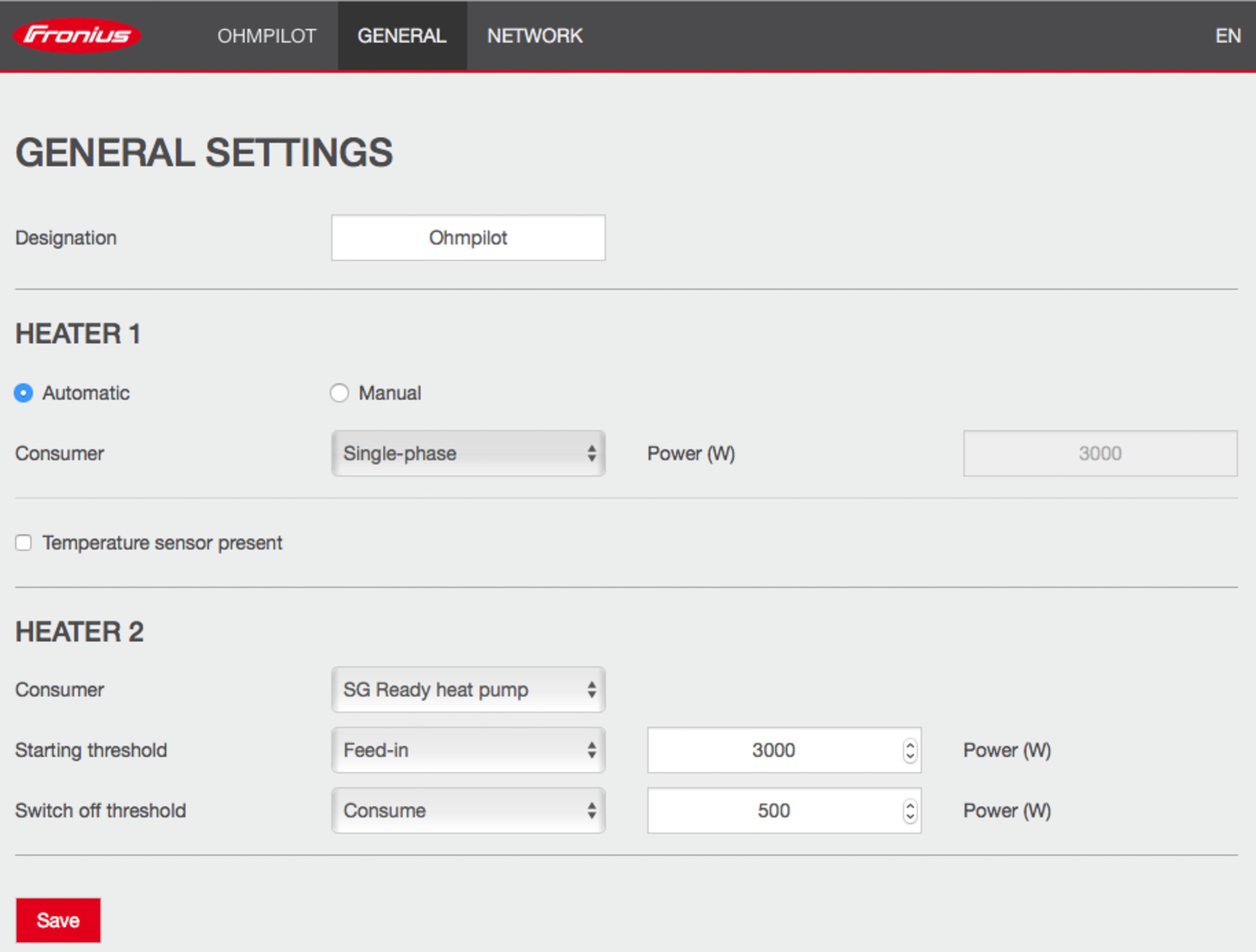
Example 1: If "Consume" has been selected for the switch-off threshold and 500 W as the power value, the heat pump is switched off as soon as consumption exceeds 500 W.
Example 2: If "Feed-in" has been selected for the switch-off threshold and a power of 500 W has been entered, the heat pump will be switched off as soon as the power being fed in is less than 500 W.
The heat pump must be connected to the same utility meter.
Between the switch-on and switch-off thresholds, the heat pump's self-consumption must also be taken into account. For example, if the heat pump consumes 3,000 watts and a hysteresis of 500 watts is to be taken into account again, the switch-on threshold can be set to a feed-in value of 3,000 watts and the switch-off threshold to a consumption value of 500 watts.

IMPORTANT! A neutral conductor must be connected to each heating element.
| (1) | Temperature sensor PT1000 |
| (2) | Hot water boiler |
| (3) | External source (e.g., gas boiler) NOTE!Relay contacts can oxidize. The voltage must be at least 15 V and the current at least 2 mA so that the relay contacts do not oxidize. |
| (4) | Heating element (max. 3 kW) |
| (5) | Ferrite rings (included in the scope of supply) |
| (6) | Output up to 3 kW (adjustable), max. 13 A ohmic load, spring-type terminal 1.5 - 2.5 mm² |
| (7) | Multifunctional relay output |
| (8) | Input - grid supply 1x 230 V, spring-type terminal 1.5 - 2.5 mm² WARNING!Short circuit If live, stripped wires touch, a short circuit is triggered. All connection work must be carried out according to the applicable electrotechnical guidelines and regulations. Observe the maximum stripping length of 10 mm. When connecting the phases, tie together the individual wires with a cable tie immediately in front of the terminal. |
| (9) | Automatic circuit breaker max. B16A |
| (10) | Residual current circuit breaker |
The Fronius Smart Meter records the current power at the feed-in point and transmits the data to the inverter. The inverter adjusts the available surplus energy to zero by activating the Ohmpilot (specifically by continuously controlling the heating element connected to the Ohmpilot). The surplus energy is consumed by the heating element (steplessly variable).
The temperature is measured by the Ohmpilot. If the temperature drops below the minimum temperature value, an external source (e.g., gas boiler) is activated until the minimum temperature is reached again, so that the Ohmpilot only uses surplus energy and does not draw any energy from the grid.
The maximum temperature must be set on the heating element thermostat. If the heating element does not have a thermostat, the Ohmpilot can also carry out this task as an alternative (see chapter Optional settings on page (→)).
The heating element is used for the legionella prevention program.
This function can also be used with a 3-phase heating element.

IMPORTANT! A neutral conductor must be connected to each heating element.
| (1) | Ferrite rings (included in the scope of supply) |
| (2) | Temperature sensor PT1000 |
| (3) | Hot water boiler |
| (4) | External source (e.g., gas boiler) |
| (5) | Heating element 1 (max. 9 kW) |
| (6) | Buffer |
| (7) | Heating element 2 (max. 3 kW) |
| (8) | Output up to 3 kW (adjustable), max. 13 A ohmic load, spring-type terminal 1.5 - 2.5 mm² |
| (9) | Multifunctional relay output |
| (10) | Output - heating element L2 |
| (11) | Output - heating element L3 |
| (12) | Input - grid supply 3x 230 V, spring-type terminal 1.5 - 2.5 mm² |
| (13) | Automatic circuit breaker max. B16A |
| (14) | Residual current circuit breaker |
Many heating systems consist of a boiler and a buffer, whereby the central heating feeds the buffer and a controller loads the hot water boiler via a pump. As with thermal photovoltaic systems, the Ohmpilot can first heat the hot water boiler and then the buffer, so that the maximum surplus PV energy can be stored.
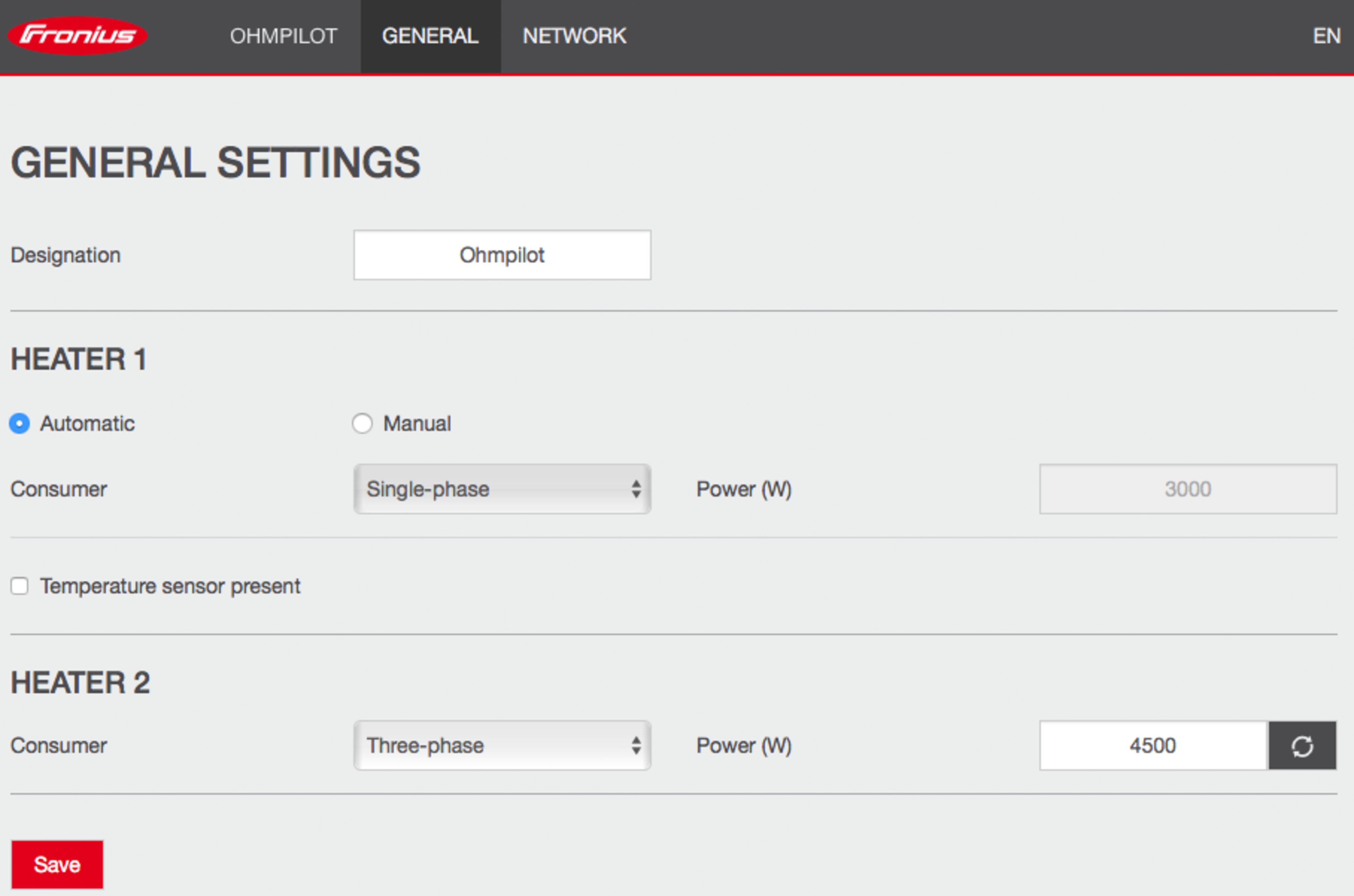
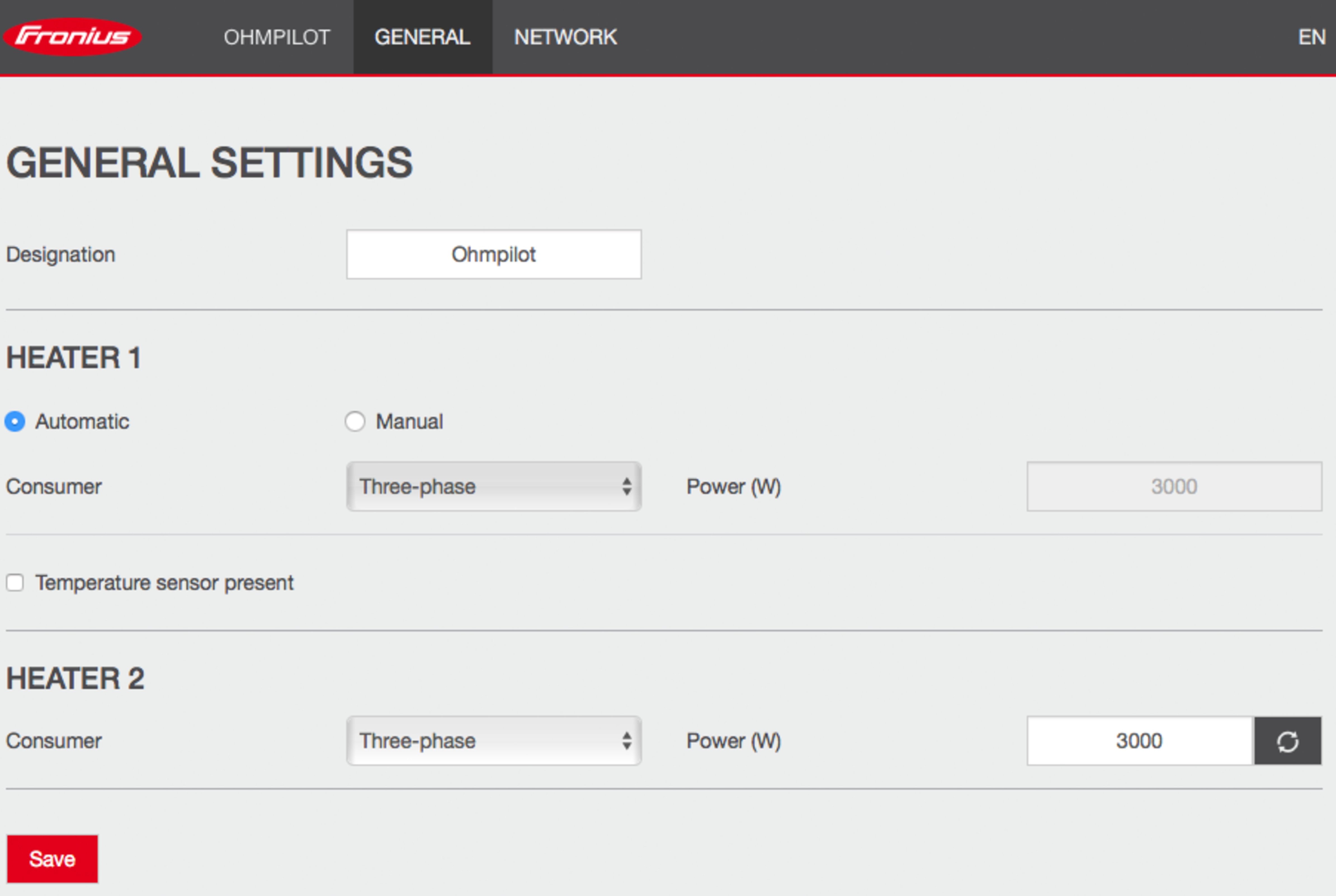
The Fronius Smart Meter records the current power at the feed-in point and transmits the data to the inverter. The inverter adjusts the available surplus energy to zero by activating the Ohmpilot (specifically by continuously controlling the heating element connected to the Ohmpilot).
For this application, two heating elements are installed, with preference being given to activating the first heating element (5). Only when the maximum temperature in the boiler (3) is reached is the second heating element activated so that the residual energy is stored, for example, in a buffer.
If no temperature sensor is connected to the Ohmpilot, after 30 minutes the Ohmpilot attempts to output energy via the first heating element once again. If a temperature sensor is present, the first heating element is activated again as soon as a temperature difference of 8°C is reached (compared to the temperature measured prior to switchover).
This switching function can also be used for layering in a boiler/buffer, so that the maximum temperature is reached in the top part of the boiler using minimal energy and the remaining energy is stored in the lower part of the boiler. This stratification effect in a storage tank also allows much more energy to be stored, as a minimum temperature is normally maintained in the upper area of the boiler. As a result, the temperature difference and thus the amount of energy is rather small. In the lower area of the boiler, a high temperature difference of, for example, 50 °C can be used.
Both the first and second heating elements can be 1-phase or 3-phase. For two 3-phase heating elements, see Application example 6. If no temperature sensor is installed, a third-party source (e.g., gas boiler) must ensure the minimum temperature.
As an alternative, the Ohmpilot can also ensure the minimum temperature. This can result in electricity being drawn from the grid. The maximum temperature must be set on the heating element thermostat. If heating element 1 (5) does not have a thermostat, the Ohmpilot can alternatively take over this task (see chapter Optional settings on page (→)). However, it is essential that heating element 2 (7) has a thermostat.
It is not possible to heat both heating elements at the same time!
IMPORTANT! A neutral conductor must be connected to each heating element.
| (1) | Ferrite rings (included in the scope of supply) |
| (2) | Temperature sensor PT1000 |
| (3) | Hot water boiler |
| (4) | External source (e.g., gas boiler) |
| (5) | Heating element 1 (max. 9 kW) |
| (6) | Buffer |
| (7) | Heating element 2 (max. 3 kW) |
| (8) | Output up to 3 kW (adjustable), max. 13 A ohmic load, spring-type terminal 1.5 - 2.5 mm² |
| (9) | Multifunctional relay output |
| (10) | Output - heating element L2 |
| (11) | Output - heating element L3 |
| (12) | Input - grid supply 3x 230 V, spring-type terminal 1.5 - 2.5 mm² |
| (13) | Automatic circuit breaker max. B16A |
| (14) | Residual current circuit breaker |
Many heating systems consist of a boiler and a buffer, whereby the central heating feeds the buffer and a controller loads the hot water boiler via a pump. As with thermal photovoltaic systems, the Ohmpilot can first heat the hot water boiler and then the buffer, so that the maximum surplus PV energy can be stored.
The Fronius Smart Meter records the current power at the feed-in point and transmits the data to the inverter. The inverter adjusts the available surplus energy to zero by activating the Ohmpilot (specifically by continuously controlling the heating element connected to the Ohmpilot).
For this application, two heating elements are installed, with preference being given to activating the first heating element (5). Only when the maximum temperature in the boiler (3) is reached is the second heating element activated so that the residual energy is stored, for example, in a buffer.
If no temperature sensor is connected to the Ohmpilot, after 30 minutes the Ohmpilot attempts to output energy via the first heating element once again. If a temperature sensor is present, the first heating element is activated again as soon as a temperature difference of 8°C is reached (compared to the temperature measured prior to switchover).
This switching function can also be used for layering in a boiler/buffer, so that the maximum temperature is reached in the top part of the boiler using minimal energy and the remaining energy is stored in the lower part of the boiler. This stratification effect in a storage tank also allows much more energy to be stored, as a minimum temperature is normally maintained in the upper area of the boiler. As a result, the temperature difference and thus the amount of energy is rather small. In the lower area of the boiler, a high temperature difference of, for example, 50 °C can be used.
Both the first and second heating elements can be 1-phase or 3-phase. For two 3-phase heating elements, see Application example 6. If no temperature sensor is installed, a third-party source (e.g., gas boiler) must ensure the minimum temperature.
As an alternative, the Ohmpilot can also ensure the minimum temperature. This can result in electricity being drawn from the grid. The maximum temperature must be set on the heating element thermostat. If heating element 1 (5) does not have a thermostat, the Ohmpilot can alternatively take over this task (see chapter Optional settings on page (→)). However, it is essential that heating element 2 (7) has a thermostat.
It is not possible to heat both heating elements at the same time!

IMPORTANT! A neutral conductor must be connected to each heating element.
| (1) | Ferrite rings (included in the scope of supply) |
| (2) | Temperature sensor PT1000 |
| (3) | Hot water boiler |
| (4) | External source (e.g., gas boiler) |
| (5) | Heating element 1 (max. 9 kW) |
| (6) | Buffer |
| (7) | Heating element 2 (max. 9 kW) |
| (8) | Contactor changeover |
| (9) | Output up to 3 kW (adjustable), max. 13 A ohmic load, spring-type terminal 1.5 - 2.5 mm² |
| (10) | Multifunctional relay output |
| (11) | Output - heating element L2 |
| (12) | Output - heating element L3 |
| (13) | Input - grid supply 3x 230 V, spring-type terminal 1.5 - 2.5 mm² |
| (14) | Automatic circuit breaker max. B16A |
| (15) | Residual current circuit breaker |
Many heating systems consist of a boiler and a buffer, whereby the central heating feeds the buffer and a controller loads the hot water boiler via a pump. As with thermal photovoltaic systems, the Ohmpilot can first heat the hot water boiler and then the buffer, so that the maximum surplus PV energy can be stored.
The Fronius Smart Meter records the current power at the feed-in point and transmits the data to the inverter. The inverter adjusts the available surplus energy to zero by activating the Ohmpilot (specifically by continuously controlling the heating element connected to the Ohmpilot).
For this application, two heating elements are installed, with preference being given to activating the first heating element (5). Only when the maximum temperature in the boiler (3) is reached is the second heating element (7) activated so that the residual energy is stored, for example, in a buffer.
If no temperature sensor is connected to the Ohmpilot, after 30 minutes the Ohmpilot attempts to output energy via the first heating element once again. If a temperature sensor is present, the first heating element is activated again as soon as a temperature difference of 8°C is reached (compared to the temperature measured prior to switchover).
This switching function can also be used for layering in a boiler/buffer, so that the maximum temperature is reached in the top part of the boiler using minimal energy and the remaining energy is stored in the lower part of the boiler. This stratification effect in a storage tank also allows much more energy to be stored, as a minimum temperature is normally maintained in the upper area of the boiler. The temperature difference and thus the amount of energy is rather small. In the lower area of the boiler, a high temperature difference of, for example, 50 °C can be used.
The switchover must be performed by an external contactor. If no temperature sensor is installed, a third-party source (e.g., gas boiler) must ensure the minimum temperature.
As an alternative, the Ohmpilot can also ensure the minimum temperature. This can result in electricity being drawn from the grid.
The maximum temperature must be set on the heating element thermostat. If heating element 1 (5) does not have a thermostat, the Ohmpilot can alternatively take over this task (see chapter Optional settings on page (→)). However, it is essential that heating element 2 (7) has a thermostat.
It is not possible to heat both heating elements at the same time!

IMPORTANT! A neutral conductor must be connected to each heating element.
| (1) | Ferrite rings (included in the scope of supply) |
| (2) | Temperature sensor PT1000 |
| (3) | Hot water boiler |
| (4) | Heating element NOTE!Single-phase and three-phase heating element This function can be used with a single-phase and three-phase heating element. |
| (5) | Circulating pump auxiliary relay NOTE!Post-flow time of the circulating pump After the end of the heating operation, the circulating pump is active for 60 seconds. |
| (6) | Output up to 3 kW (adjustable), max. 13 A ohmic load, spring-type terminal 1.5 - 2.5 mm² |
| (7) | Multifunctional relay output NOTE!Relay contacts can oxidize. The voltage must be at least 15 V and the current at least 2 mA so that the relay contacts do not oxidize. |
| (8) | Input - grid supply 1x 230 V, spring-type terminal 1.5 - 2.5 mm² CAUTION!Danger due to live stripped wires coming into contact with each other A short circuit can be triggered and damage the device. All connection work must be carried out according to the applicable electrotechnical guidelines and regulations. Observe the maximum stripping length of 10 mm. When connecting the phases, tie together the individual wires with a cable tie immediately in front of the terminal. |
| (9) | Automatic circuit breaker max. B16A |
| (10) | Residual current circuit breaker |
The Ohmpilot can also control a circulating pump in a heating system in parallel to a heating element via the floating contact of the device controller. This is possible with all circulating pumps that have an auxiliary relay.
The designation of the floating contact on the Ohmpilot is NC W NO. When the contact is activated, the switching rocker (W) switches from the "normally open" (NO) position to "normally closed" (NC).
In heating operation, this contact is activated and the circulating pump runs as Heater 2 in parallel to the heating element, which is operated via the output Heater 1.
To prevent the auxiliary relay of the circulating pump from switching on and off continuously in case of low or fluctuating PV power, the Ohmpilot is equipped with a delay. This has a positive effect on the wear and the service life of the relay and the pump.
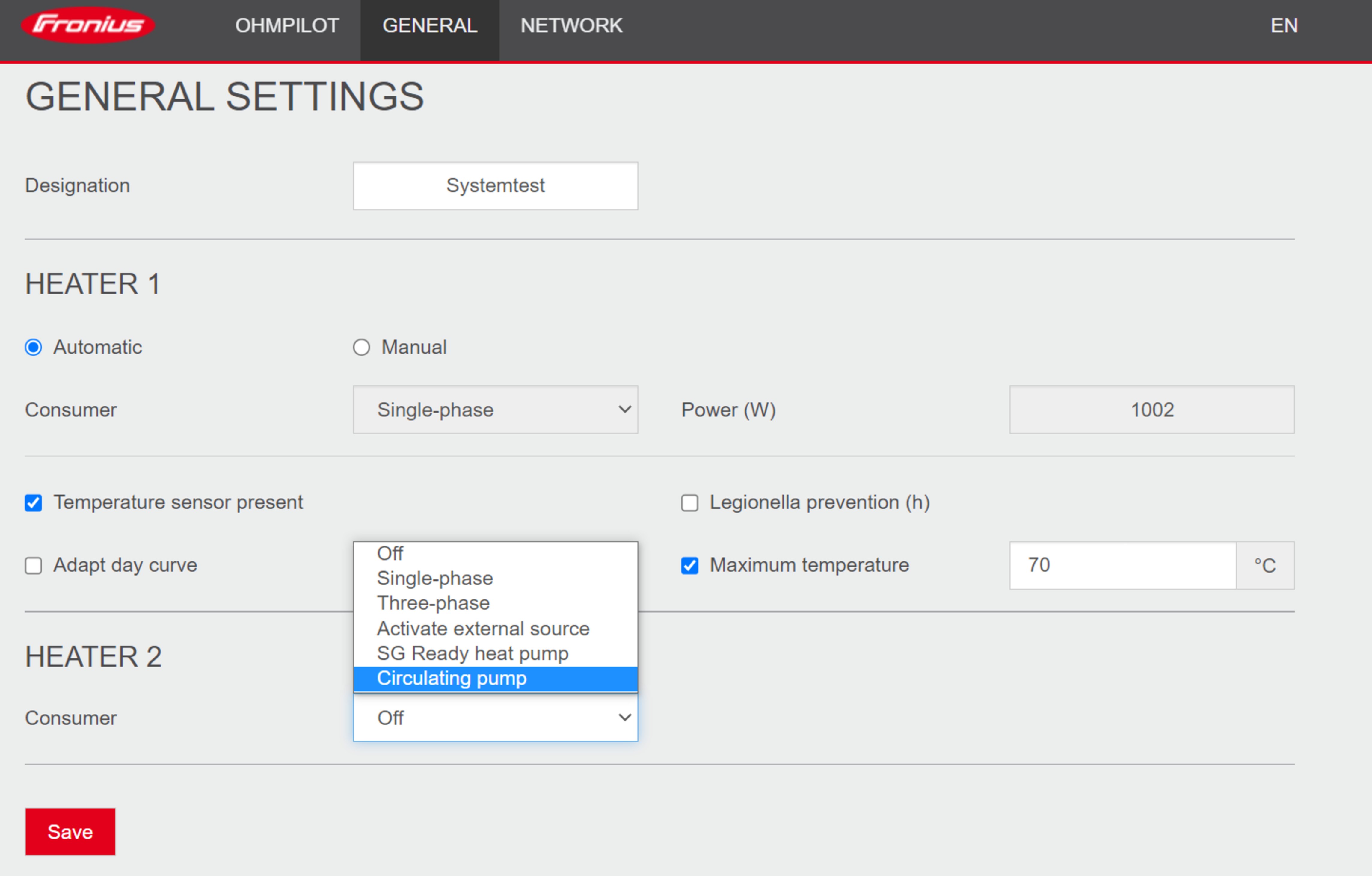
If the circulating pump option is selected, no other heater can be controlled by the Ohmpilot. The output Heater 1 controls the heating element, which, in combination with the circulating pump, heats a hot water tank.
The data connection is required for communication between the inverter and the Ohmpilot. The inverter mainly sends default values to the Ohmpilot. For some applications, it is necessary to make settings via the Ohmpilot user interface.

There are 3 possible communication channels:
Fronius Datamanager 2.0 software version
In order to communicate with the Ohmpilot, software version 3.8.1-x onwards must be installed on the SnapINverter series inverter (Fronius Datamanager 2.0).
The data connection is required for communication between the inverter and the Ohmpilot. The inverter mainly sends default values to the Ohmpilot. For some applications, it is necessary to make settings via the Ohmpilot user interface.
There are 3 possible communication channels:
Fronius Datamanager 2.0 software version
In order to communicate with the Ohmpilot, software version 3.8.1-x onwards must be installed on the SnapINverter series inverter (Fronius Datamanager 2.0).
Each inverter with a Fronius Smart Meter automatically pairs with the Ohmpilot. If there are several inverters with a Fronius Smart Meter in the network, the Ohmpilot must be manually paired under System Information on the user interface of the inverter to be connected.
Guidance on how to access the user interface of the inverter can be found in the operating instructions of the respective device.

Ohmpilot connections | Fronius Smart Meter connections | Fronius SnapINverter / GEN24 connections |
|---|---|---|
D+ | Rx/M+ | D+/M1+ |
D- | Tx/M- | D-/M1- |
- | GND | GND |
Danger if cables are mixed up
If data cables and live mains cables are mixed up, this can result in personal injury and damage to property.
Use data cables that are clearly distinguishable from the mains cables.
Mark cables (e.g., by labeling)
Defective cabling is signaled by the red LED indicator flashing once.
DIP switch settings
Switch | Setting |
|---|---|
DIP 1-3 | Modbus address BCD |
DIP 4 | Reserve |
DIP 5 | Terminating resistor (120 Ohm) |
The Ohmpilot automatically obtains its IP address from the DHCP server.
The inverter automatically searches for the Ohmpilot, and the search process may take up to 5 minutes. If the red LED is unlit and the green LED is flashing, the Ohmpilot is working correctly.
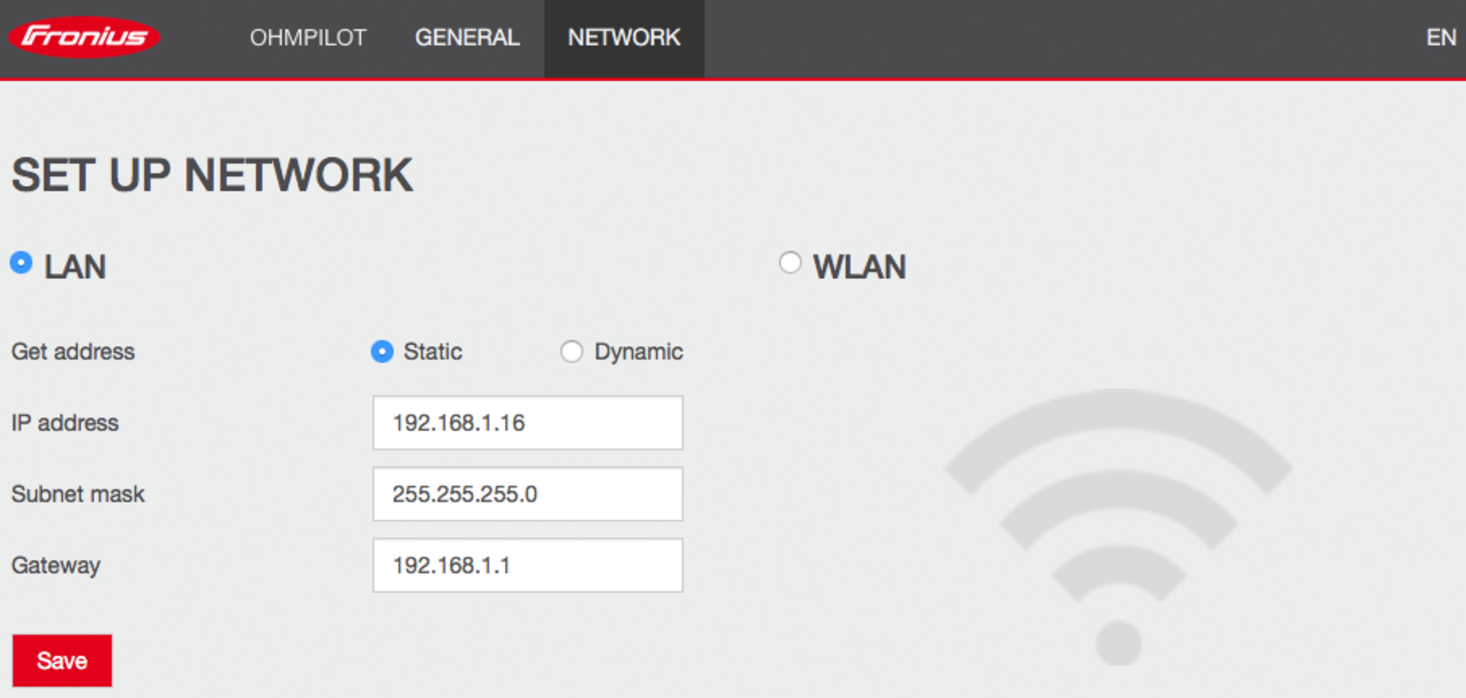
Access the Ohmpilot via the network.
In networks with a DNS suffix, the Ohmpilot can be reached at http://ohmpilotL.<DNS suffix>, e.g., http://ohmpilotL.fronius.com
In order to set the IP address manually, the option Static must be selected. Then enter the desired IP address.
There are two options for connecting the Ohmpilot to an existing WLAN network:
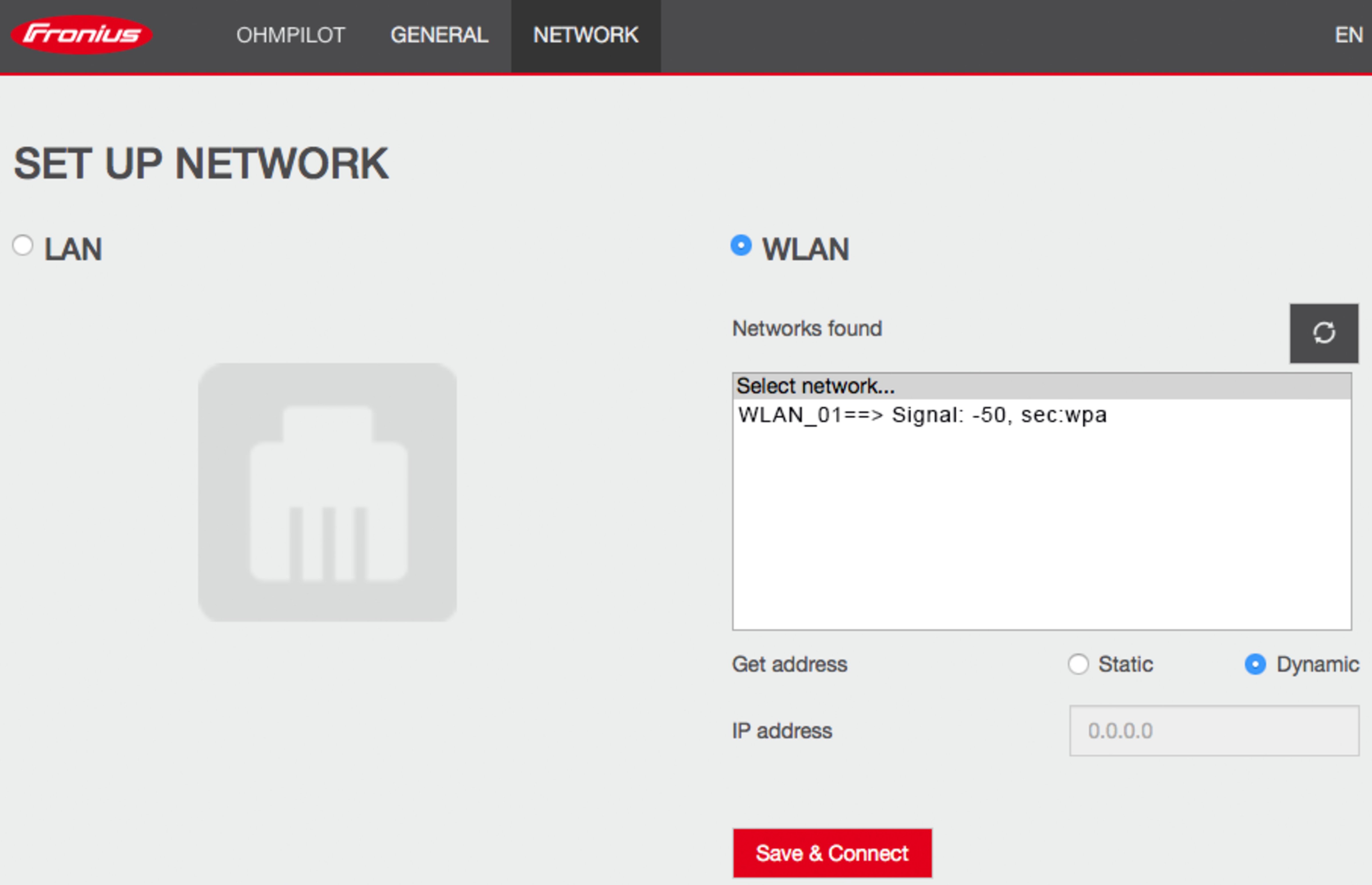
Network scan
WLAN network scan is not possible when the access point mode is activated.
End the access point mode by pressing the button again and repeat the process
The user interface can be used to set a static IP address for the Ohmpilot.
The Ohmpilot can then be reached at http://ohmpilotW.local or at the fixed IP address assigned. Alternatively, the Ohmpilot can also be searched for in the network using the Fronius Solar.web app.
Connection to the inverter
Only one inverter can connect to the Ohmpilot.
DNS networks
In networks with a DNS suffix, the Ohmpilot is available at http:// ohmpilotW.<DNS suffix>, e.g., http://ohmpilotW.fronius.com
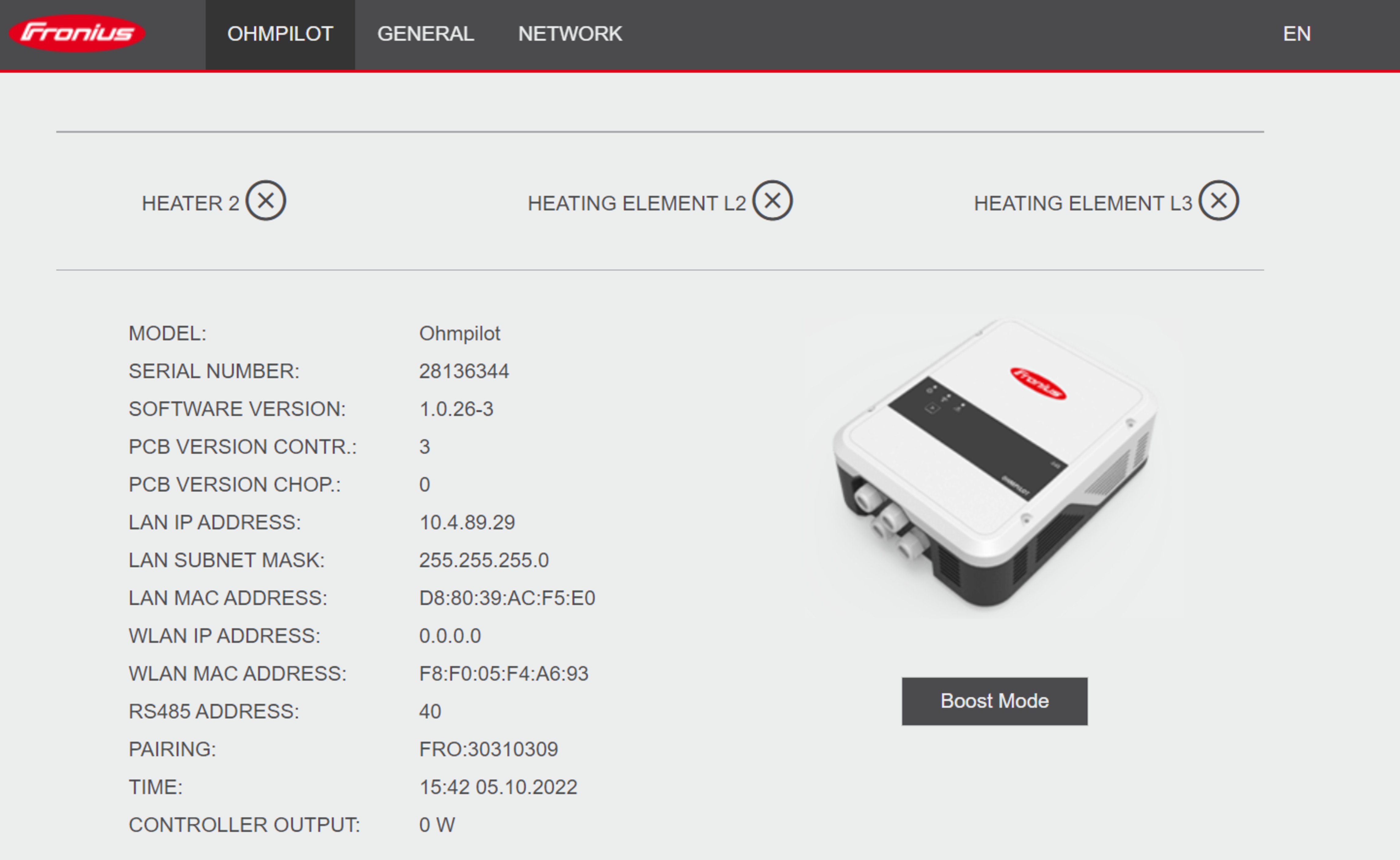
Boost mode is used to briefly supply loads on output Heater 1 with 100% of the available power. Over a maximum period of 4 hours, the dimming level is activated at 100%, the phases L2 and L3 are switched through. This can result in electricity being drawn from the grid.
Boost mode can be activated and deactivated by pressing the function button on the Ohmpilot (see Indications/controls on the device) or via the user interface.
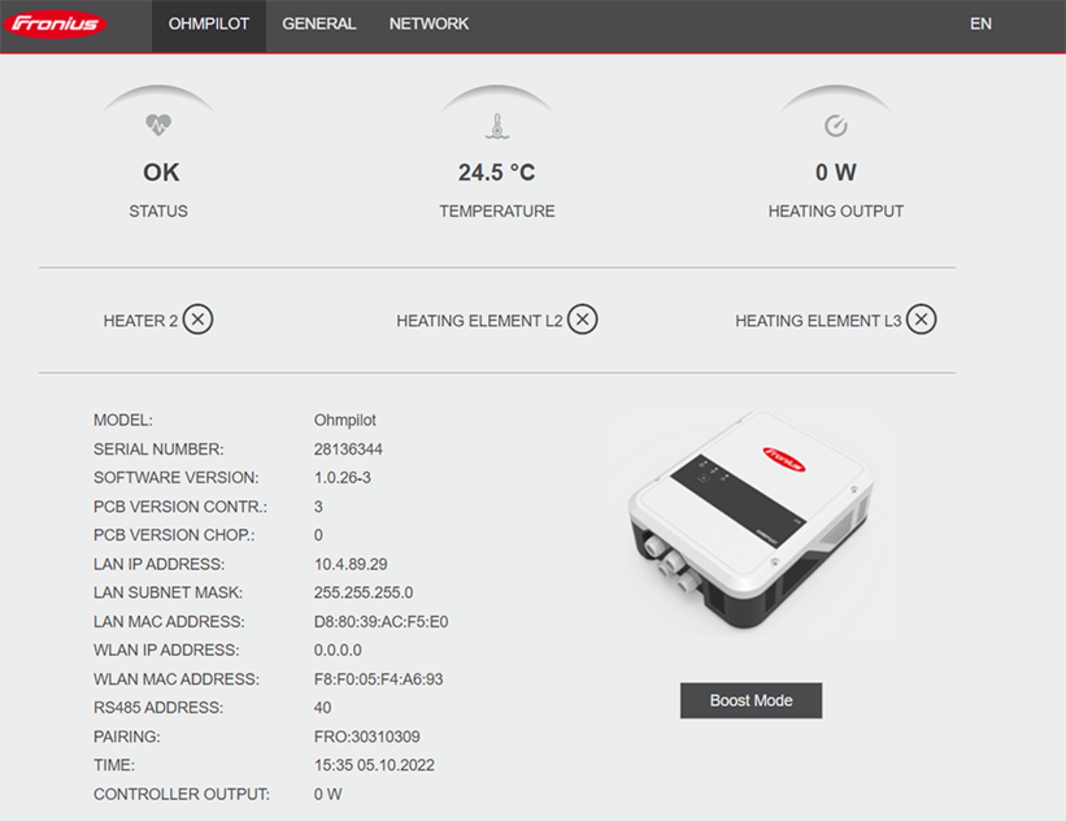
Status | |
|---|---|
OK | Ohmpilot is operating in normal mode. |
Minimum temperature | The minimum temperature has been undershot. Heater 1 heats up to 100%. |
Legionella prevention | Legionella prevention program is active. Heater 1 heats up to 100%. |
Boost | The Ohmpilot was manually set to Boost Mode. Heater 1 heats up to 100%. |
Error | An error has been detected. Further information is displayed in Fronius Solar.web. |
Temperature | Current measured temperature. A valid value is only displayed when a temperature sensor is connected. |
Heat output | Current power being used by the Ohmpilot. |
Heater 2 | Heater 2 is active. Heater 2 may be a second heating element, a heat pump, or an external source (e.g., gas-fired heating). |
L2 heating element | Phase 2 of 3-phase heating element is active. |
L3 heating element | Phase 3 of 3-phase heating element is active. |
Applicability
The settings described here can be made for all the application examples described above.
Applicability
The settings described here can be made for all the application examples described above.
Danger from Legionella
Legionella bacteria can cause serious diseases. Despite the Legionella prevention function, the possibility of water contamination with Legionella cannot be excluded.
Run the Legionella prevention function regularly.
Ensure continuous circulation and removal of hot water.
Check hot water temperature regularly
If the boiler is operated at a temperature of less than 60°C for a longer period of time and no hygiene storage tank is being used, appropriate measures must be taken to kill Legionella bacteria.
For the private sector, it is recommended to run the Legionella prevention function at least once a week (168 hours). The actual interval depends on the size of the tank and the set temperature.
A PT1000 temperature sensor is required for this function, which can be obtained from Fronius under item number 43,0001,1188.
When the Legionella prevention function is activated, the hot water is heated to 60 °C at the set interval.
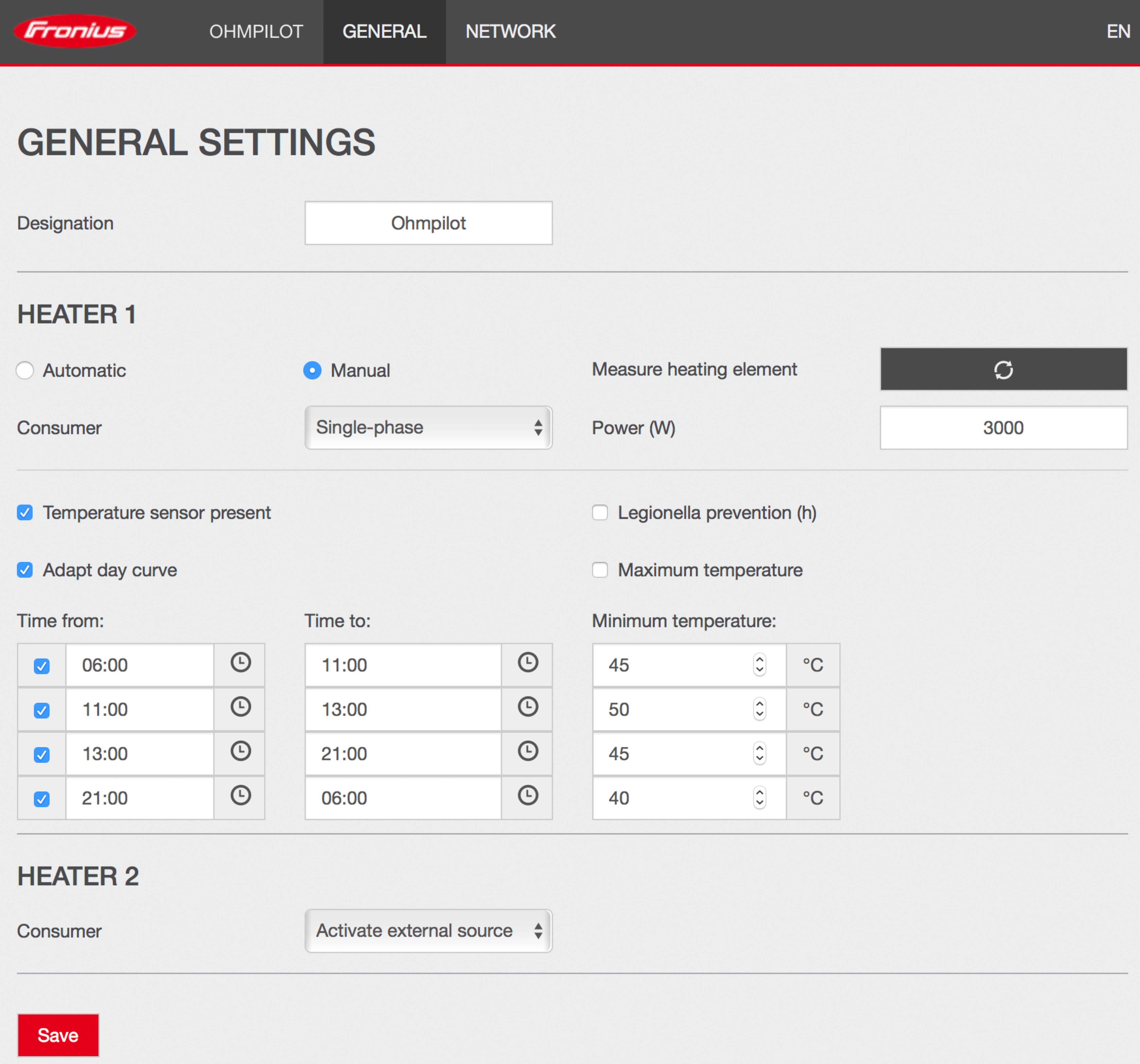
This function ensures that the temperature does not fall below a desired value. If there is not enough surplus power, the external source - if activated - is activated or power is drawn from the grid to ensure a minimum temperature.
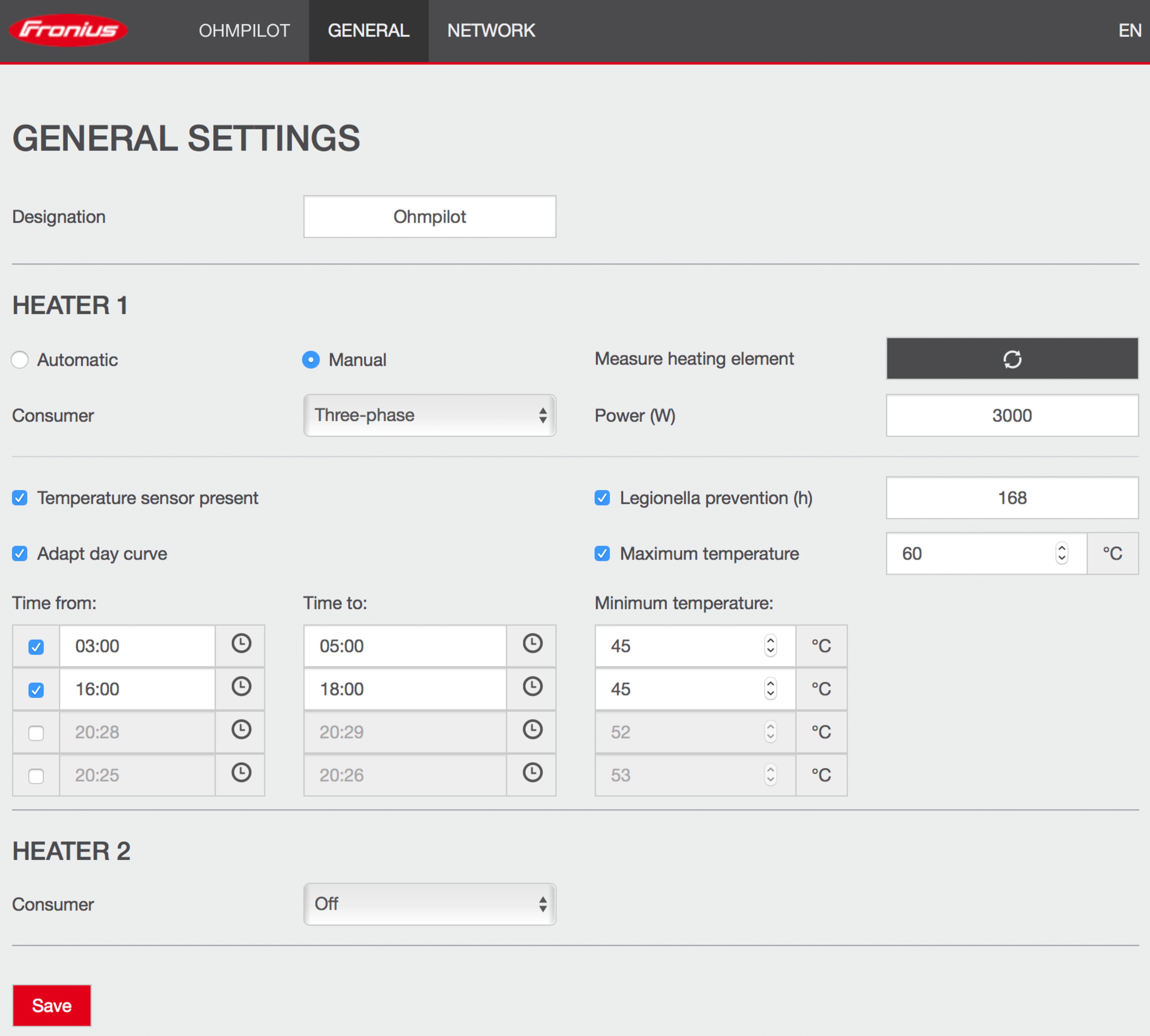
Up to four time periods and minimum temperatures can be defined. For example, higher hot water temperatures are available in the evening. More potential for the surplus power during the day is then possible by selecting a lower minimum temperature.
Undefined time ranges.
If no time ranges are defined, no heating will be carried out using energy from the grid or the external source during this time. Only PV surplus energy is used.
If time ranges overlap, the higher temperature is used, so that, for example, a basic temperature of 40° C can be set for the whole day and is increased to 50° C at certain times.
Primary heat source.
If Heater 1 is the primary heat source, the day curve must be adjusted to ensure the desired minimum temperature. A PT1000 temperature sensor is required for this function, which can be obtained from Fronius under item number 43,0001,1188. The temperature sensor must be mounted above the heating element/external source so that the continuous supply of hot water is ensured.
Example |
|
|---|---|
Time/Desired temperature | Use case |
03:00 - 05:00 / 45°C | So that hot water is available for showering at 6:00 in the morning. After showering, the hot water is only heated with surplus energy. |
16:00 - 18:00 / 45°C | If there is not enough surplus energy, the hot water is reheated for showering. After showering, there is no more reheating of the tank, so the heat losses remain low. |
If Heater 1 does not have an adjustable thermostat, this function can be used to limit the temperature.
This function is only possible for Heater 1.
If a second heating element is being used as Heater 2, it must have a thermostat. A PT1000 temperature sensor is required for this function, which can be obtained from Fronius under item number 43,0001,1188. The position of the temperature sensor should be just above the heating element, so that the incoming cold water is immediately heated again and thus the maximum amount of storage is used.
Status codes | |||
|---|---|---|---|
HS = Heating element TS= Temperature sensor WR = Inverter FQ = External source (e.g., gas boiler) | |||
Code | Description | Cause | Remedy |
906 | Heating element 1 defective - Short circuit L1 | The load on L1 is higher than 3 kW. Short circuit to L1. | Check heating element 1. Check cabling. |
907 | HS 1 - Overload on L2 | Current on L2 greater than 16 A | Check HS 1 and replace HS if necessary. |
909 | HS 1 defective - L1 high-resistance | No current flowing through L1/L2/L3. L1/L2/L3 of HS 1 defective. Phase L1/L2/L3 interrupted. | Check L1/L2/L3. Check connections L1/L2/L3. |
912 | HS 2 defective - Short circuit L1 | The load on L1 is higher than 3 kW. Short circuit to L1. | Check HS 2. Check cabling. |
913 | HS 2 - Overload on L2 | Current on L2 greater than 16 A | Check HS2 and replace HS if necessary. |
915 | HS 2 defective - L1 high-resistance | No current flowing through L1/L2/L3. L1/L2/L3 of HS 2 defective. Phase L1/L2/L3 interrupted. | Check L1/L2/L3. Check connections L1/L2/L3. |
918 | Relay 2 (phase L2) defective | Relay R2/R3 does not switch. | Replace Ohmpilot. |
920 | TS short circuit | Input resistance TS less than 200 ohms. No PT1000 TS connected. TS defective. | Check the cable and connections on the TS cable. Replace TS. |
921 | TS not connected or defective | No TS connected (input resistance greater than 2000 ohms). TS is activated (should be deactivated). TS cable defective. TS defective. No PT1000 TS connected. | Connect TS to device. Disable TS via the user interface (if no sensor is required). Check TS cable. Replace TS. |
922 | 60 °C for Legionella protection could not be reached within 24 hours. | FQ switched off/defective. (922 only). TS was mounted incorrectly. Heating system incorrectly dimensioned (too much hot water consumption, etc.) HS/TS defective. | Switch on FQ (only 922). Mount the TS above the HS (in the protective tube). Legionella prevention via the user interface. Replace HS/TS. |
924 | FQ could not reach minimum temperature within 5 hours. | FQ switched off/defective. FQ not connected to Ohmpilot. TS mounted incorrectly. Heating system incorrectly dimensioned (too much hot water consumption, etc.). TS defective. | Switch on FQ. Connect FQ to relay 1. Install TS above the heating register of the FQ. Check the minimum temperature setting. Replace TS. |
925 | Time not synchronized | Time not synchronized in the last 24 hours. Router has been switched off/reconfigured. | Check connection between Ohmpilot and inverter. Switch on the router. Check network settings. |
926 | No connection to the inverter | No connection between WR and Ohmpilot. WR switched off. The Ohmpilot also needs a connection to the WR at night. Router switched off/defective/reconfigured. Night shutdown activated on the inverter. Poor WLAN connection between inverter or Ohmpilot and router. | Check connections. Switch on WR. Update software. Switch the Ohmpilot and WR off and on again. Deactivate the night shutdown of the WR. On Fronius SnapINverters, set the night mode to "ON" on the display under Setup > Display Settings > Night Mode. Switch on the router. Better position the WLAN antenna. Check network settings. |
927 | Ohmpilot overtemperature | Ambient temperature too high (> 40 °C). The output of the heating element is too high. Ventilation slots are covered. | Install Ohmpilot in a cooler location. Use a heating element with a permissible output. Clear ventilation slots. |
928 | Ohmpilot undertemperature | Ambient temperature too low (< 0 °C). | Install Ohmpilot in a warmer place. Installation outdoors is not permitted! |
| Residual current circuit breaker triggers | Neutral conductor (N) and phase (L) mixed up. | Connect N and L correctly. |
| Ohmpilot does not consume any surplus | Thermostat on heating element has switched off. Safety thermostat (STC) on the heating element has tripped. | Wait until the thermostat switches on again. Reset safety thermostat |
| Ohmpilot consumes only part of the surplus power | Heating element output is lower than surplus power. | if necessary, select a larger heating element |
| Power at the feed-in point is not always adjusted to 0 | It takes a few seconds to compensate for load and generation fluctuations. |
|
| After switching on, the green LED continuously flashes 2 times | Thermostat on heating element has switched off. The heating element is not connected. | Turn up the thermostat briefly for the power measurement. Connect the heating element. |
| After a power failure, the Ohmpilot no longer works | After a power failure, if the Ohmpilot does not receive an IP address after 40 s, the Ohmpilot automatically assigns the following fixed IP address: 169.254.0.180 (only valid if the Ohmpilot is connected to the router via WLAN). | Restart Ohmpilot so that the WLAN connection is re-established. |
General data |
|
|---|---|
Dimensions (height x width x depth) | 350 mm x 280 mm x 110 mm |
Weight | 3.9 kg |
Protection class | IP 54 |
Installation | Wall |
Ambient temperature range | 0 to 40 °C |
Permissible humidity | 0%-99% (non-condensing) |
Cooling | Convection |
Storage temperature | -40 to 70 °C |
EMC emission class | B |
Overvoltage category | 3 |
Pollution degree | 3 |
Input data |
|
|---|---|
Frequency | 50 Hz |
Nominal voltage | 230 V / 400 V |
Max. input current | 1x 16 A / 3x 16 A |
Interfaces |
|
|---|---|
Modbus RTU | RS 485, max. 300 m, shielded and twisted |
LAN | Ethernet at least CAT5, shielded |
WLAN | Standard IEEE 802.11 b/g/n |
Temperature sensor | PT1000 (max. 30 m) |
Output data |
|
|---|---|
Analogue output 1-phase/3-phase | Continuously variable 0-3 / 0-9 kW |
Analogue nominal current per phase | 13 A |
Analogue output short circuit current | 16 A (max. 5 seconds) |
Relay output max. current | L2 / L3 16 A (max. 5 seconds) |
Multifunctional relay output | min. 15 V / 2 mA; max. 16 A (max. 5 seconds) |
Efficiency during rated operation | at least 98% |
Consumption during standby | typically 1.8 W |
Tests/specifications per EN60730 Section 1 Table 7.2
6a | Construction | Electronic RS 2.5.5, independently mounted RS |
19 | Screwless terminals | 2.10.6.1 type X mounting |
24 | Classification of the RS according to protection against electric shock, Section 6.8 | Safety class I 6.8.3 |
29 | Type of shutdown or open circuit for each circuit | Micro-interruption per 2.4.4. |
30 | PTI value of the insulation materials used for insulation | PTI 175 in accordance with 6.13.2 |
31a | Type of ground conductor connection | N in accordance with 7.4.3, grounding terminal in accordance with 9.1.1 |
39 | Operating principle | Operating principle TYPE 1 in accordance with 2.6.1 |
40 | Additional properties for operating principle | C in accordance with 6.4.3.3 |
51 | Glow wire test temperatures (Sections 21.2.1, 21.2.2, 21.2.3, and 21.2.4) | Housing 550 °C, cable gland/strain-relief device 650 °C; category B in accordance with EN 60730-1:2000/A1:2004; |
75 | Rated surge voltage (Sections 2.1.12, 20.1) | In accordance with EN 61000-6-2:2005, EN 60730-1:2011, EN 301 489-1 (V1.9.2) |
77 | Temperature of the ball pressure test | In accordance with 21.2.1, 21.2.2, 21.2.3, and 21.2.4, case (housing): |
80 | Rated surge voltage for creepage distance or contact-gap | In accordance with EN 61000-6-2:2005, EN 60730-1:2011, EN 301 489-1 (V1.9.2) |
Detailed warranty conditions specific to your country can be found at www.fronius.com/solar/garantie .
Detailed warranty conditions specific to your country can be found at www.fronius.com/solar/garantie .
Waste electrical and electronic equipment must be collected separately and recycled in an environmentally sound manner in accordance with the European Directive and national law. Used equipment must be returned to the distributor or through a local authorized collection and disposal system. Proper disposal of the used device promotes sustainable recycling of resources and prevents negative effects on health and the environment.
Packaging materialsCE mark
The devices conform to all the requisite and relevant standards and guidelines that form part of the relevant EU directive, and are therefore permitted to display the CE mark.