Fronius Wattpilot Flex Home 11 C6 / Home 22 C6 / Pro 11 C6E / Pro 22 C6E
download
The warnings and safety instructions in these instructions are intended to protect people from possible injury and the product from damage.
Indicates an immediately dangerous situation
Serious injury or death will result if appropriate precautions are not taken.
Action step to escape the situation
Indicates a potentially dangerous situation
Death or serious injury may result if appropriate precautions are not taken.
Action step to escape the situation
Indicates a potentially dangerous situation
Minor or moderate injury may result if appropriate precautions are not taken.
Action step to escape the situation
Indicates impaired work results and/or damage to the device and components
The warnings and safety instructions are an integral part of these instructions and must always be observed to ensure the safe and proper use of the product.
The device has been manufactured in line with the state of the art and according to recognized safety standards.
Incorrect operation or misuse
Serious to fatal injuries to the operator or third parties as well as damage to the device and other property of the operator may result.
All persons involved in the commissioning, maintenance, and servicing of the device must be appropriately qualified and have knowledge of working with electrical installations.
Read these operating instructions in full and follow them carefully and precisely.
The operating instructions must always be kept to hand wherever the device is being used.
IMPORTANT!
Labels, warning notices, and safety symbols are located on the device. A description can be found in these operating instructions.
Tampered-with and non-functioning protection devices
Serious to fatal injuries as well as damage to the device and other property of the operator may result.
Never bypass or disable protection devices.
Any protection devices that are not fully functional must be repaired by an authorized specialist before the device is switched on.
Loose, damaged, or under-dimensioned cables
An electric shock can be fatal.
Use undamaged, insulated, and adequately dimensioned cables.
Fasten the cables according to the specifications in the operating instructions.
Loose, damaged, or under-dimensioned cables must be repaired or replaced immediately by an authorized specialist.
Installations or modifications to the device
The device may be damaged
Do not carry out any alterations, installations, or modifications to the device without first obtaining the manufacturer's permission.
Damaged components must be replaced.
Only use original spare parts.
In certain cases, even though a device complies with the standard limit values for emissions, it may affect the application area for which it was designed (e.g., when there is equipment that is susceptible to interference at the same location or if the site where the device is installed is close to either radio or television receivers). If this is the case, the operator is obliged to take action to rectify the situation.
During operation, due to the high electrical voltages and currents, local electromagnetic fields (EMF) occur in the environment around the inverter and the Fronius system components as well as in the area of the PV modules including the supply lines.
In the case of exposure to humans, the required limit values are observed when the products are used in line with the intended use and the recommended distance of at least 20 cm is observed.
If these limit values are complied with, according to current scientific knowledge, no health-endangering effects from EMF exposure are to be expected. If wearers of prostheses (implants, metal parts in and on the body) as well as active physical aids (pacemakers, insulin pumps, hearing aids, etc.) are in the vicinity of components of the PV system, they must consult with the responsible doctor regarding possible health risks.
The device has a built-in residual current protection module with residual current detection (IΔn = 20 mA AC and 6 mA DC).
The residual current detection tripping characteristic is as follows.

 max. normative DC max. normative DC | |
 max. normative AC max. normative AC | |
 typ. DC of sensor typ. DC of sensor | |
 typ. AC of sensor typ. AC of sensor |
The Wattpilot Flex has a built-in residual current protection module with residual current detection. A separate residual current circuit breaker (type A, IΔn = 30 mA AC) must be connected upstream of the installation. Comply with all national regulations and standards during installation.
The device has an integrated surge protection device (SPD). This can negatively affect the insulation measurement. According to normative specifications, carry out the insulation measurement with a reduced voltage of 250 V DC and a resistance of >=1 MΩ. During the measurement, the Wattpilot displays the status code Ground fault detected (see Status codes).
Alternatively, disconnect the Wattpilot from the power supply and carry out the insulation measurement directly on the grid lead with a voltage of 500 V DC.
Technical data, warning notices, labels, and safety symbols are located on the Fronius Wattpilot Flex. Do not remove or paint over the information. The notices and symbols warn against incorrect operation that may result in serious injury and damage.
Symbols on the device: | |
 | CE label – confirms compliance with applicable EU directives and regulations. The product has been tested by a specific notified body. |
 | WEEE marking – waste electrical and electronic equipment must be collected separately and recycled in an environmentally sound manner in accordance with the European Directive and national law. This product contains a built-in lithium-ion battery. Have the battery removed by a qualified technician before disposing of the device. Do not dispose of the battery with household waste. It can be disposed of at a designated collection point or returned to the distributor free of charge. |
 | RCM marking – tested according to the requirements of Australia and New Zealand. |
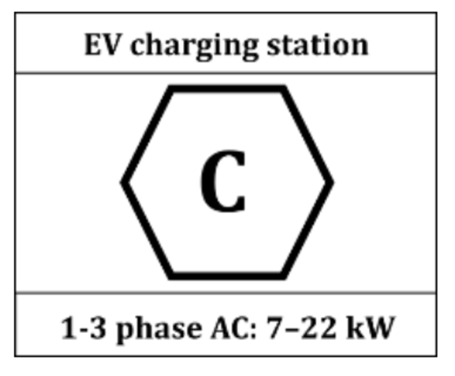 | Charging port marking – charging station identifier for electric vehicle charging. Category C corresponds to the type 2 plug and a maximum charging voltage of 480 V. |
Information on MID-compliant measuring device (Fronius Wattpilot Flex Pro)
Technical data, warning notices, labels, and safety symbols are located on the Fronius Wattpilot Flex. Do not remove or paint over the information. The notices and symbols warn against incorrect operation that may result in serious injury and damage.
Symbols on the device: | |
| CE label – confirms compliance with applicable EU directives and regulations. The product has been tested by a specific notified body. |
| WEEE marking – waste electrical and electronic equipment must be collected separately and recycled in an environmentally sound manner in accordance with the European Directive and national law. This product contains a built-in lithium-ion battery. Have the battery removed by a qualified technician before disposing of the device. Do not dispose of the battery with household waste. It can be disposed of at a designated collection point or returned to the distributor free of charge. |
| RCM marking – tested according to the requirements of Australia and New Zealand. |
| Charging port marking – charging station identifier for electric vehicle charging. Category C corresponds to the type 2 plug and a maximum charging voltage of 480 V. |
Information on MID-compliant measuring device (Fronius Wattpilot Flex Pro)
The conventions regarding how information is presented in the document, which are set out below, have been defined in order to increase the readability and comprehensibility of the document.
Application notes
IMPORTANT! Indicates application notes and other useful information. It does not indicate a harmful or dangerous situation.
Software
Software functions and elements of a graphical user interface (e.g., buttons, menu items) are highlighted in the text with this mark up.
Example: Click Save.
Instructions for action
Accessories | Item number |
|---|---|
Fronius Wattpilot Flex Pedestal | 4,240,196 |
Fronius Wattpilot Flex Connection Plate | 4,240,191 |
Fronius Wattpilot Flex Gasket Set | 4,240,192 |
10 RFID tags | 4,240,181 |
Type 2 plug holder | 4,240,188 |
IMPORTANT!
Other accessory components such as charging cable adapters or cable extensions must not be used.
The full text of the EU Declaration of Conformity is available on the following website:www.fronius.com
Compatibility with the connected devices (see list below), suitable data communication, and a Fronius Smart Meter at the feed-in point are prerequisites for using certain Wattpilot functions (e.g., PV surplus).
Suitable Fronius inverters
*Requirement:
**Requirement:
Suitable generators can be inverters or wind power plants, for example. A prerequisite for compatibility with external generators is that no other self-consumption controllers (e.g., battery, power-to-heat) are operated in parallel. This can lead to photovoltaics optimization (PV optimization) malfunctions. The proportion of energy consumed by other loads is not taken into account in the Fronius Solar.wattpilot app, as the power is only known at the grid connection point.
Requirement:
* For connection via Modbus RTU, the generator requires a Fronius Datamanager Box 2.0 (item number 4,240,125).
For more information, see Data communication with inverter.
The following link provides current webinars and how-to videos for the Fronius Wattpilot.
This document provides detailed information and instructions to ensure that all users can use the device safely and efficiently.
Data security for network and Internet connection
Unsecured networks and a lack of safeguards can result in data loss and unauthorized access. Observe the following points for safe operation:
Operate inverters and system components on a private, secure network. A WiFi network is considered secure if security standard WPA 2 is satisfied as a minimum.
Keep the network devices (e.g., WiFi routers) up to date with the latest technology.
Keep the software and/or firmware updated.
Use a wired network to ensure a stable data connection.
For security reasons, do not make inverters and system components accessible from the Internet via port forwarding or Port Address Translation (PAT).
Use the solutions provided by Fronius for monitoring and remote configuration.
The optional communication protocol Modbus TCP/IP1) is an unsecured interface. Only use Modbus TCP/IP if no other secured data communication protocol (MQTT2)) is possible (e.g., compatibility with older Smart Meters).
1) TCP/IP - Transmission Control Protocol/Internet Protocol
2) MQTT - Message Queuing Telemetry Protocol
To ensure that your device is always working optimally and that you benefit from the latest features and security improvements, we recommend that you regularly check for updates.
Check the Fronius Solar.wattpilot app regularly for updates (see also Firmware update on page (→)).
Regular updates keep your device up to date, giving you the best possible performance and security.
Fronius International GmbH retains the copyrights of these operating instructions.
Text, illustrations, and other media correspond to the technical state of the art at the time of publication. Fronius reserves the right to make changes. If you have any suggestions for improvement or have found a mistake in this document, we would be most grateful for your comments.
Fronius Wattpilot Flex is a permanently mounted charging station for charging electric vehicles for fixed connection to an AC/three-phase network.
The Wattpilot may only be used for the purpose of charging battery-powered electric vehicles and plug-in hybrid vehicles. The device complies with the criteria for electric vehicle charging stations (AEVCS) in accordance with DIN EN IEC 61439-7.
The Wattpilot Flex Home 22 CP6 / Pro 22 CP6E device variants have an integrated shutter on the live contacts of the charging plug.
The Wattpilot Flex Pro 11 C6E, Wattpilot Flex Pro 22 C6E and Wattpilot FlexPro 22 CP6E devices meet the requirements for conformity with calibration law, which means that all measurements and billing of the charged energy are carried out precisely and in accordance with the law.

| (1) | Device including mounting bracket |
| (2) | 2 strain-relief devices for the mains cable |
| (3) | 6 dowels for mounting bracket and charging plug holder |
| (4) | 6 screws TX20 4.5 x 50 mm for mounting bracket and charging plug holder |
| (5) | 4 screws TX20 3.0 x 10 mm for mounting the device on the mounting bracket (1 screw as a spare) |
| (6) | Charging plug holder |
| (7) | 2 ID chips |
| (8) | Reset card |
| (9) | Enclosed documents:
|
The Wattpilot has WLAN (see Commissioning with app on page (→)).
Data communication can also be established via cable (see step 3 in Wall mounting and data cabling on page (→)). The following connection options are available:

| (1) | Rating plate position |
| (2) | LED status indicator |
| (3) | Card reader |
| (4) | Operating mode buttons |
| (5) | kWh display: Session kWh, Total kWh, Power kWh |
| (6) | Mounting bracket |
| (7) | Type 2 charging cable |
| (1) | Rating plate position |
| (2) | LED status indicator |
| (3) | Card reader |
| (4) | Operating mode buttons |
| (5) | kWh display: Session kWh, Total kWh, Power kWh |
| (6) | Mounting bracket |
| (7) | Type 2 charging cable |
Behind the symbol  is the card reader for reading ID chips and the reset card.
The card reader uses RFID (radio-frequency identification). RFID is the transmitter‑receiver technology for automatic and contactless identification with radio waves.
The buttons are actuated by touch; due to the capacitive touch detection, touching them while wearing gloves can lead to limited results.
The operating mode can be changed by touching the buttons. The following charging modes are available:
Display |
| Operating mode |
|---|---|---|
 |
| Standard mode
|
 |
| Eco Mode
|
 |
| Next Trip Mode
|
The LED status indicator on the Wattpilot indicates whether the system is switched on and shows the current status of the Wattpilot.
LED |
| Meaning |
|---|---|---|
 |
| Starting
|
  |
| Ready
|
 |
| Authentication
|
  |
| Wait for vehicle
|
  |
| Charging
|
 |
| Charging plug not plugged in
|
 |
| Charging finished
|
 |
| ID chip detected
|
 |
| Invalid value
|
 |
| Earthing test deactivated
|
 |
| Internal communication fault
|
 |
| Residual current detected
|
 |
| Earth fault detected
|
 |
| At least one phase of the power supply is missing
|
 |
| Temperature too high
|
 |
| Charge controller error
|
 |
| Update
|
 |
| Update successful
|
 |
| Update failed
|
 |
| Reset card detected
|
 |
| Tamper detection
|
The kWh display is located below the operating mode buttons and alternately displays the following values.
Session kWh
Displays the charged energy of the current charging process.
Total kWh
Displays the total charged energy of all charging processes.
Power kW
Displays the current charging power.
The ID chip can be used to personalize access to the Fronius Wattpilot. The ID chip is used for authentication and for recording user-specific charging amounts.
In the app settings, authentication for charging can be activated under "Access management" and "Authentication required" (see Access management on page (→)). Charging with authentication activated can be carried out after scanning the supplied ID chip or by providing confirmation in the app. To scan, hold the ID chip directly in front of the card reader of the Wattpilot.
Each ID chip can be assigned a name in the app under "ID chips". The stored charging amount per ID chip can be viewed in this menu (see ID chips on page (→)).
No authentication is required in order to assign the charging amount to the ID chips.
The reset card resets all settings (e.g. access management, WLAN, and LED settings) to the factory settings. The device can also be reset using the Fronius Solar.wattpilot app. The taught-in ID chips and the corresponding charging amounts continue to be stored.
The following information is printed on the reset card.
Resetting the Wattpilot

Keep the reset card safe!
The reset card contains all access data.
TIP: Place the reset card in the supplied self-adhesive transparent bag and keep it in a safe place.
The Wattpilot can be used like any other charging station. Actuating an operating mode button (see Operating mode buttons on page (→)) allows the user to switch between the different charging modes (see Different charging modes on page (→)).
The Wattpilot can be used like any other charging station. Actuating an operating mode button (see Operating mode buttons on page (→)) allows the user to switch between the different charging modes (see Different charging modes on page (→)).
The Fronius Wattpilot can automatically switch between 1‑phase and 3‑phase charging. The automatic phase changeover enables charging with a low start-up power (1‑phase with 1.38 kWh) in the case of a PV surplus. In addition, 1‑phase charging has the advantage that the charging power can be regulated in smaller increments (0.23 kW) and a small PV surplus can be used more efficiently. As 1‑phase charging is limited by the vehicle, it makes sense to switch to 3‑phase charging at a higher PV surplus. This allows higher maximum charging power levels to be achieved.
The phase changeover can be set automatically or manually (see PV surplus on page (→)).
Unbalanced load management limits the total charging current, which means that the unbalanced load is below the desired value. It is important to comply with the phase unbalanced load limits in order to protect the grid, make charging electric vehicles efficient and comply with the applicable regulations.
The maximum phase unbalanced load can be set by a technical specialist in accordance with the applicable regulations (see Grid settings on page (→)).
Do not exceed the phase unbalanced load!
Select the three-phase power level in such a way that the maximum permissible phase unbalanced load is not exceeded. To do this, amend the settings in the Fronius Solar.wattpilot app under “Settings” > “Grid requirements”.
A minimum charging time of 5 minutes is stored.
To prevent permanent switching of the relays and to increase the service life of the Wattpilot, a minimum charging time of 5 minutes is stored.
The surplus energy of a PV system (photovoltaic system) can be used. The prerequisites for this are a compatible inverter in the same network as the Wattpilot and a Fronius Smart Meter (for more information, see Data communication with inverter on page (→)).
Setting limit values ensures that the available PV surplus power is distributed to the loads. The limit values created allow a PV battery to be sufficiently charged or the energy to be stored in the form of hot water. The surplus PV power is then used to charge a vehicle.
PV surplus regulation.
One Wattpilot per photovoltaic system.
The PV surplus regulation works with one Wattpilot per photovoltaic system.
If several Wattpilot devices are connected to one inverter, "Use PV surplus" may only be activated on one Wattpilot. For all other Wattpilot devices, "Use PV surplus" must be deactivated (for more information, see Activating cost optimization on page (→)).
It is possible to set a start-up power level (specified in kilowatts/kW). This must be reached by the photovoltaic system before the Wattpilot starts charging the vehicle with the minimum current.
It is possible to set a 3‑phase power level (specified in kW). This must be reached by the photovoltaic system before the Wattpilot switches from 1‑phase to 3‑phase charging.
The settings for the start-up power level and 3‑phase power level can be made under Activating cost optimization in the Fronius Solar.wattpilot app.
The power level can only be regulated in increments of 1 ampere. The table below lists the charging current in amperes (A) and the corresponding charging power for 1‑phase and 3‑phase charging in kilowatts (kW). 1‑phase in 0.23 kW increments, 3‑phase in 0.69 kW increments. The values are based on the assumption that the voltage is exactly 230 or 400 V.
Charging current [A] | 6 | 8 | 10 | 12 | 14 | 16 | 20 | 24 | 32 |
|---|---|---|---|---|---|---|---|---|---|
1-phase [kW] | 1.38 | 1.84 | 2.3 | 2.76 | 3.22 | 3.68 | 4.6 | 5.52 | 7.36 |
3-phase [kW] | 4.14 | 5.52 | 6.9 | 8.28 | 9.66 | 11 | 13.8 | 16.56 | 22 |
Example

 | Photovoltaic generation |
 | Electric vehicle |
The figure illustrates the behavior of the Wattpilot with a set start-up power level of 1.38 kW and a 3‑phase power level of 4.14 kW. If the PV surplus is less than 1.38 kW, the vehicle is not charged.
If the PV surplus is between 1.38 and 4.14 kW, the Wattpilot regulates the charging power in 0.23 kW increments.
If the PV surplus is above 4.14 kW, the Wattpilot switches from 1‑phase charging to 3‑phase charging and regulates the charging power in 0.69 kW increments.
The minimum charging power of electric vehicles is usually 1.38 kW.
In the case of smaller photovoltaic systems, we recommend setting the start-up power level below 1.38‑kW so that sufficient energy is charged. The electricity that is not covered by the photovoltaic system, however, is drawn from the grid. This results in a power mix of self-consumption and grid supply.
A start-up power level below 1.38 kW results in a power mix.
Charging with PV surplus can be activated and adjusted in the Fronius Solar.wattpilot app (see Activating cost optimization on page (→)).
Priorities in the system between battery, Ohmpilot and Wattpilot
The priority of the Wattpilot can be influenced via the "PV battery limit value" and "Ohmpilot limit value" settings in the Fronius Solar.wattpilot app (see chapter Activating cost optimization on page (→)). Depending on the level of the selected limit values, it is possible to define under which conditions the charging of the electric vehicle starts. The temperature limit value of the Ohmpilot can only be used if a temperature sensor is connected to the Ohmpilot. To set the Wattpilot priority, the energy management priority settings on the user interface of the inverter must also be taken into account.
If no temperature sensor is connected to the Fronius Ohmpilot, a temperature of 0 °C is assumed. If the Wattpilot is to be prioritized over the Ohmpilot, the "Ohmpilot limit value" must be set to 0 °C. In the event of a sensor break, the Ohmpilot is supplied with power before the Wattpilot.
Example
The electric vehicle must always be charged with PV surplus before the battery and the Ohmpilot. In the Solar.wattpilot app, the limit value for the battery is set to 0% and the limit value for the Ohmpilot is set to 0 degrees. The electric vehicle is immediately charged with PV surplus, regardless of the state of charge of the battery or the temperature of the Ohmpilot.
Priority in the inverter | Wattpilot | Battery** | Ohmpilot |
|---|---|---|---|
Battery** > Ohmpilot | Priority 3 until SOC* and temperature limit value reached, then priority 1 | Priority 1 until SOC*, then priority 2 | Priority 2 until temperature limit value reached, then priority 3 |
Ohmpilot > Battery** | Priority 3 until SOC* and temperature limit value reached, then priority 1 | Priority 2 until SOC, then priority 3 | Priority 1 until temperature limit value reached, then priority 2 |
Priority in the inverter | Wattpilot | Ohmpilot |
|---|---|---|
Ohmpilot | Priority 2 until temperature limit value reached, then priority 1 | Priority 1 until temperature limit value reached, then priority 2 |
Priority in the inverter | Wattpilot | Battery** |
|---|---|---|
Battery** | Priority 2 until SOC*, then priority 1 | Priority 1 until SOC*, then priority 2 |
*SOC - State of Charge of the stationary battery
**Fronius-compatible DC coupled battery
IMPORTANT!
The energy management with the digital outputs (I/Os) on the Fronius inverter must not be used for load management of the Wattpilot! The priorities of the loads are not clearly assigned.
Tariff zones
If you are a customer of a flexible electricity tariff retailer, you can use the flexible electricity tariff. This is taken into account when using Eco Mode and Next Trip Mode.
Retailer
The flexible electricity tariff can be used if electricity is purchased from electricity retailers and charged for hourly via the electricity exchange, e.g.,
The Wattpilot queries the various retailer tariffs from the electricity exchange directly via the Internet. It is possible to specify a price threshold (Eco Mode price limit) below which charging starts.
IMPORTANT!
The prices displayed show the current tariffs on the electricity exchange. Additional costs may apply depending on the provider.
Example

The figure shows the development of the electricity price of an electricity supplier over 24 hours. The hourly tariffs are retrieved from the electricity exchange at a specific time for the next day.
The Wattpilot Flex Pro meets all the requirements of a MID-compliant measuring device. In addition, the following aspects must be taken into account with regard to compliance with measurement and calibration law:
IMPORTANT!
If the device display shows an error, all charging operations that take place up to the acknowledgment of the error are not billable according to the calibration law.
Prerequisite
To be able to use Boost Mode, there must be a stationary battery storage system in the PV system and Eco or Next Trip Mode must be selected.
Function
Activating the Boost uses the energy for charging directly from the stationary battery storage system. As a result, low-cost energy can be obtained, even if no PV surplus is available. In the Boost settings, it is possible to set how much residual energy (SOC) should remain in the stationary battery. In addition, you can set whether the charge from the stationary battery should be used once, or for as long as the vehicle is plugged in.
When Boost is activated, it can take up to 10 minutes for the battery to discharge at maximum power. If the inverter has already reached the maximum total power (through PV) or the battery cannot be discharged, the Wattpilot still charges with at least 1.4 kW. The minimum SOC of the battery at the inverter must be greater than the "Discharge until" limit value.
Example
Let's imagine that your stationary battery storage system is 80% charged. Due to the current weather conditions, no additional energy is stored. If you now activate the Boost, the stored energy will be transferred to your vehicle. Note that the discharging limit of the stationary battery is taken into account (e.g., 20% set = 20% of the energy always remains in the stationary battery storage system). Activating Boost also means that the discharge is continued as long as the vehicle is connected (perform setting in the app). If the weather conditions change and the PV surplus is fed into the stationary battery storage system again, your vehicle will continue to be charged until it is unplugged. A residual amount of energy of 20% is always retained in the stationary battery storage system.
In standard mode, charging takes place at the preset amperage (e.g., 16 A). In the app (see Current level on page (→)), the charging current can be adjusted in 1 ampere increments.
Charging with a low charging current is more gentle on the vehicle, whereas charging at a high charging current enables rapid charging. Charging takes place from the grid if necessary.
Standard Mode
In this charging mode, the PV surplus and the flexible electricity tariff are not taken into account.
No further settings are required for charging in standard mode.
In Eco Mode, a vehicle is only charged when low-cost electricity is available. Charging can either take place with cheaply purchased electricity (see Flexible electricity tariff on page (→)) or surplus energy produced by the photovoltaic system (see PV surplus on page (→)). There is no guarantee that charging will occur.
Prerequisite
Charging in Eco Mode is only possible if PV surplus and/or a Flexible electricity tariff is activated under PV surplus in the Fronius Solar.wattpilot app.
Change mode for guaranteed charging.
If there is no surplus generated power or cheap electricity available, charging is not carried out in Eco Mode.
For guaranteed charging, change to standard or Next Trip Mode.
Enable
The Eco Mode can be configured under Activating cost optimization (see page(→)) and activated by pressing the operating mode button or via the Fronius Solar.wattpilot app.
The battery of the photovoltaic system is discharged first!
If the system contains a stationary battery, when the electricity price falls below the threshold, the battery of the photovoltaic system is discharged first in order to charge an electric vehicle before grid current is drawn.
Example

| Photovoltaic generation |
 | Electric vehicle |
 | Household consumption |
In Eco Mode, the electric vehicle is connected to the Wattpilot at around 15:00 hrs, as although a fixed additional range for the electric vehicle is not necessary, cheaper electricity is to be used for charging. In the Fronius Solar.wattpilot app, the PV surplus and/or flexible electricity tariff must be activated and set under cost optimization. Household consumption is covered by photovoltaic generation and the electric vehicle is charged with the PV surplus. Charging takes place using the PV surplus until around 20:00 hrs. Between 02:00 and 05:00 hrs, the electricity price falls below the defined price limit. The electric vehicle is charged with cheap electricity during this period.
Charging in Eco Mode
PV surplus | Price limit | Wattpilot |
|---|---|---|
No | No | No charging |
No | Yes | Max. charging |
Yes | No | Charging with PV surplus |
Yes | Yes | Max. charging |
In Next Trip Mode, a vehicle is charged as cheaply as possible until the end of the self-selected time with the set charging amount. The time charging starts is selected in such a way that the desired charging amount is charged at least one hour before the charge end. Charging takes place at the most cost-effective time window. The PV surplus and flexible electricity tariff settings are taken into account. If the Eco Mode after Next Trip Mode function is activated, the Wattpilot continues charging with low-cost energy after the set charging amount has been reached.
The charging amount is specified in kilometers and calculated on the basis of an average consumption (18 kWh/100 km). External conditions (such as season, driving speed, vehicle model) may cause deviations in the actual range. When setting the charging amount, the actual state of charge of the electric vehicle battery is not read out. The set charging amount is charged in addition to the charging amount available in the electric vehicle.
Activation
Set the mode under Next Trip Mode in the Fronius Solar.wattpilot app.
After activating the mode, charging is started briefly to calculate a charging schedule taking into account the possible charging power. If no flexible electricity tariff is activated, charging is started at the latest possible time in order to charge with a possible PV surplus and to conserve the battery of the electric vehicle. If no time is provided for the calculation of the charging schedule, charging starts immediately.
Internet connection required if a flexible electricity tariff is activated.
The Next Trip Mode LED flashes red when the flexible electricity tariff (in Next Trip Mode) is activated and there is no connection to the data of the electricity provider. Charging starts at the latest possible time in order to reach the set charging amount.
If the charging cable is disconnected and reconnected while Next Trip Mode is activated, the calculation is repeated and the set charging amount is charged in addition to the existing charging amount. Changes to the settings of the Fronius Solar.wattpilot app result in a recalculation of the charging schedule. If the change is made during Next Trip Mode charging, the range charged up to this point is added to this.
If Stay in Eco Mode is activated, the cost optimization settings are also taken into account in Next Trip Mode.
The battery of the photovoltaic system is discharged first.
If the system contains a stationary battery, the battery is discharged to charge the electric vehicle before grid current is drawn.
Orange flashing LEDs if the charging amount cannot be reached or stored.
If the set charging amount cannot be charged in the specified time or if the vehicle cannot store the set charging amount, the LEDs flash orange.
Reduce the charging amount or extend the charging time.
Example

| Photovoltaic generation |
| Electric vehicle |
| Household consumption |
The daily journey to work and back home is 50 km and must start at 08:00 hrs. In the Fronius Solar.wattpilot app, the kilometers and the departure time must be entered under Next Trip Mode. 18 kWh is used as the basis for the calculation of 100 km. The electric vehicle is plugged in and charged at approximately 15:00 hrs. If PV surplus is available, charging is carried out with PV surplus. The remaining charging amount is guaranteed to be charged in the electric vehicle at the latest possible time. The charge is calculated in such a way that it is completed at the latest one hour before departure.
When the Wattpilot is connected to the Internet, the device supports dynamic load management, known as Dynamic Load Balancing. Dynamic Load Balancing distributes the current dynamically while charging with several Wattpilots, depending on their prioritization. The function is available with the following system components:
Activation
The Dynamic Load Balancing defines the maximum delivery current for the feed-in point. The function takes into account the electricity generated by the photovoltaic system and the consumption. Any number of Wattpilots can be dynamically controlled. The dynamic control uses the maximum possible charging current.
Dynamic Load Balancing monitors the available current per phase (including PV surplus) at the feed-in point and dynamically distributes this to one or more Wattpilots. The Wattpilots are supplied with the maximum available current. The maximum current (delivery current) is not exceeded and can be limited for the Wattpilots.
Charge 1-phase electric vehicles evenly with multiple Wattpilots.
In the case of multiple Wattpilots, connect the phases differently so that the load is distributed evenly among 1-phase electric vehicles.
The maximum delivery current must be set to match the post-meter fuse.
Control system example

| (1) | Photovoltaic system |
| (2) | Inverter |
| (3) | Loads (e.g., TV, washing machine, light) |
| (4) | Fronius Smart Meter |
| (5) | Fronius Wattpilot |
| (6) | Electric vehicle |
| (7) | Grid |
In the control system example, 32 A are drawn from the public grid. 8 A are generated by the PV system. Of a total of 40 A, 20 A are accounted for by the loads in the household. The Dynamic Load Balancing distributes 20 A to the connected Wattpilots. This enables charging of, for example, two electric vehicles with 10 A each.
Charging is interrupted or does not start.
If Dynamic Load Balancing is activated, charging interruptions may occur. Some electric vehicles encounter problems when starting charging again.
In the case of systems with multiple Wattpilots, charging priorities can be set. The charging stations (electric vehicles) with a higher priority are supplied with current first; charging stations with a lower priority have to wait. If there is current left over, it is shared among the lower-priority Wattpilots.
The vehicles that are to be charged first and with the maximum available current must be assigned a high priority. A low priority can be assigned to vehicles that should wait to charge until sufficient current is available.
In the case of Wattpilots with the same priority, the available current is shared equally.
Example 1

Distribution of the charging current with three Wattpilots with different priorities (one with high priority, two with medium priority). |
Example 2
Distribution of the charging current with three Wattpilots (X, Y, Z) with the same priority. Each Wattpilot is assigned the minimum charging current (unless the minimum charging current is no longer available). If there is charging current left over, it is distributed wherever possible, starting with the first Wattpilot in the loop.
Wattpilot X has a minimum charging current of 6 A, Wattpilot Y 10 A and Wattpilot Z 6 A. There is 15 A of charging current to be distributed. The charging current is distributed as follows.
The 15 A charging current was distributed among the equally prioritized Wattpilots and charged. As soon as charging current is available again, the electric vehicle is charged at Wattpilot Y.
Install the Wattpilot indoors or outdoors, in a location with or without restricted access. The device does not support an optional ventilation function.
The following additional criteria must be taken into account when choosing a location:
 | The Fronius Wattpilot is suitable for operation outdoors, with and without direct sunlight. When in direct sunlight, output is reduced for the following charging currents:
| |
 |
| The Wattpilot is suitable for operation in a well-ventilated indoor area. |
 |
| Do not operate the Wattpilot in areas where there is an increased risk from ammonia gases. |
For environmental conditions, see Technical data on page (→).
Warping of the mounting bracket on uneven surfaces.
An uneven surface can cause the mounting bracket to warp. It is no longer possible to attach the Wattpilot to the mounting bracket. This may result in damage to the device.
Select a suitable location on an even surface.
Failure to comply with the reporting obligation
Failure to comply with the reporting obligation may result in fines or sanctions.
Check with the utility whether there is a reporting obligation for charging stations in the target country.
If required, report the charging station to the responsible utility.
Install the Wattpilot indoors or outdoors, in a location with or without restricted access. The device does not support an optional ventilation function.
The following additional criteria must be taken into account when choosing a location:
| The Fronius Wattpilot is suitable for operation outdoors, with and without direct sunlight. When in direct sunlight, output is reduced for the following charging currents:
| |
|
| The Wattpilot is suitable for operation in a well-ventilated indoor area. |
|
| Do not operate the Wattpilot in areas where there is an increased risk from ammonia gases. |
For environmental conditions, see Technical data on page (→).
Warping of the mounting bracket on uneven surfaces.
An uneven surface can cause the mounting bracket to warp. It is no longer possible to attach the Wattpilot to the mounting bracket. This may result in damage to the device.
Select a suitable location on an even surface.
Failure to comply with the reporting obligation
Failure to comply with the reporting obligation may result in fines or sanctions.
Check with the utility whether there is a reporting obligation for charging stations in the target country.
If required, report the charging station to the responsible utility.
Installation height
Install the Wattpilot at a height between 80 cm and 150 cm above the ground. This protects the device from contact and ensures ease of use.
 | The Wattpilot is designed for wall-mounting on a vertical, level wall. | |
 |
|
|
Mount the Wattpilot on the optionally available support foot to allow for flexible positioning. Up to two devices can be attached to the support foot. Observe the criteria for Selecting a location.
Incorrect operation or misuse
Serious to fatal injuries to the operator or third parties as well as damage to the device and other property of the operator may result.
Observe the requirements for the qualification of the technical personnel.
Know and observe the 5 safety rules for working on electrical systems:
Disconnect.
Secure against anyone inadvertently turning on the power again.
Ensure the system is no longer live.
Ground and short circuit.
Cover or shield neighboring parts that are energized.
Open or damaged housing.
This can result in severe personal injury and damage to property due to high voltage and/or fire.
Do not use the device if the housing is damaged or open.
Send in the device for repair.
Loose parts in the housing.
This can result in severe personal injury and damage to property due to high voltage and/or fire.
Do not use the device if there are loose parts in the housing.
Send in the device for repair.
Loose or damaged cables
Damaged or exposed cables can result in severe personal injury and damage to property.
Do not use the device if the cables attached to or plugged into the device are damaged.
Adequately support the weight of the device and the charging cable.
Provide mechanical relief for the cables.
Lay the charging cable securely to avoid the risk of tripping over the charging cable.
Wet or dirty plugs
Charring caused by prolonged usage can result in severe personal injury and damage to property.
Only mount the device vertically.
Dry wet plugs in a de-energized state.
Clean soiled plugs in a de-energized state.
Gassing vehicle batteries
This can result in serious personal injury.
Only use in well-ventilated areas.
Driving away with the charging cable connected
This can result in severe personal injury or damage to property.
Disconnect the charging cable from the electric vehicle before driving away.
Do not bypass the safety devices of the electric vehicle.
Never pull the plug out of the plug connection by the cable!
Observe the specifications of the utility regarding 1‑phase charging and the asymmetrical network load that may result.
Single-core | Multi-stranded/fine-stranded with ferrule |
|---|---|
 |  |
Connect round copper conductors to the terminals of the Wattpilot Flex as described in chapter Installing the grid connection . Pay attention to the cable temperature when selecting a cable:
Grid lead charging current | Minimum cable temperature requirement |
|---|---|
0-16 A | 70 °C |
>16 A-32 A | 90 °C |
Single conductor contact
If conductors bend in the housing, the contactability within the terminal may be impaired. This can cause heat to develop in the housing and the device to switch off.
Bend all conductors according to the installation variant.

Make sure that the mounting bracket is not warped or deformed.

Align the wall bracket horizontally with the level at the top and draw four drill holes.

Drill the four holes. Maintain a distance of 0.8-1.5 meters between the mounting bracket and the ground. For installations in Sweden, the minimum distance to the ground is 1.4 meters.

Data communication via cable (RJ45)
Insert the data communication cable into the housing from behind and connect it to the RJ45 connection. Alternatively, establish a connection via WiFi.

Data communication via cable (LSA)
Insert the data communication cable into the housing from behind. Connect it to the LSA terminals. Alternatively, establish a connection via WiFi.
Before final installation of the device on the wall, feed in the mains cable if the cable is guided into the housing from the rear.

Insert the wall plugs into the drill holes and fasten the mounting bracket with the screws supplied (see Scope of supply).

Using a cable tie, secure the data communication cable in one of the positions shown above.
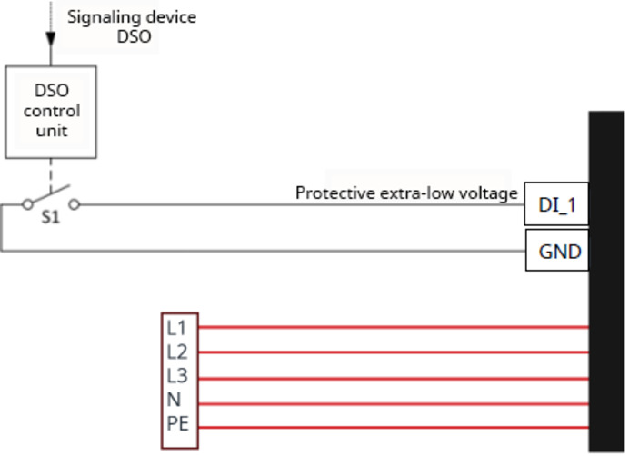
The insulated switching contact of the digital output can be used, among other things, for the following regulatory requirements:
A shunt trip must be connected as part of the wall mounting process due to the cable gland.

Connect a 2-pin cable to the shunt trip.

Insert the cable into the housing and connect it to the digital output.
Fit the charging plug holder as follows.

Mark the drill holes and drill the holes. Insert the dowels and secure the cable bracket.
Short circuit or overload
Serious personal injuries and damage to the device may result.
Connect an automatic circuit breaker with the following specifications to the grid lead:
Characteristic B or C
16 A (11 kW charging power) or 32 A (22 kW charging power)
Use 1 or 2-pin (single-phase grid connection) or 3 or 4-pin (three-phase grid connection) switches
The short circuit current (Icc) available at the installation site must not exceed 10 kA.
Mains voltage
An electric shock can be fatal.
During installation, the mains cable must be installed by a technical specialist in accordance with national standards.
Always make sure the circuit is disconnected and de-energized before carrying out any connection work.
Incorrect or insufficient connection of the phases.
This can result in electrical shocks, short circuits, damage to the device or fire hazards.
For 1-phase operation, use phase L1.
To supply current to the Wattpilot, a phase must be connected to L1.
The unused phases L2 and L3 must be insulated (contact protection).
The Wattpilot Flex has a built-in residual current protection module with residual current detection. A separate residual current circuit breaker (type A, IΔn = 30 mA AC) must be connected upstream of the installation. Comply with all national regulations and standards during installation.

Turn off the automatic circuit breaker.

Prepare the cables
Depending on the connection version, strip the conductors according to the template on the packaging of the Wattpilot Flex. Strip the conductors by 12 mm.

Insert the 5-pin mains cable into the device from the rear through the opening. Connect the individual conductors according to the illustration. Adjust the rubber grommet to the cable cross-section. The rubber grommet protects the device from water ingress.
Grid connection from above is only permitted indoors.

Insert the 5-pin mains cable into the device from above through the opening. Put the rubber grommet over the mains cable to seal it.

Connect the individual conductors of the mains cable as shown in the illustration. Fit the appropriate strain-relief device (10-15 mm or 15-20 mm).

Insert the 5-pin mains cable into the device from below through the opening.

Connect the individual conductors of the mains cable as shown in the illustration. Fit the appropriate strain-relief device (10-15 mm or 15-20 mm).

If the mains cable is being inserted into the device from above, break out the marked area on the housing using a suitable tool.

Place the housing cover onto the device as shown.

Secure the housing cover with 3 screws TX20 3.0 x 10 mm.

Turn on the automatic circuit breaker.
Type 2 charging cable with integrated shutter
The Wattpilot Flex Home 22 CP6 / Pro 22 CP6E device variants have an integrated shutter on the live contacts of the charging plug. The shutter protects the contacts when the cable is not connected. If the shutter is tampered with, this could result in damage to the charging cable and the Wattpilot Flex.
Do not open or remove the shutter manually.
The shutter opens automatically when inserted correctly into the vehicle socket.
IMPORTANT!
Charging cable adapters and cable extensions can negatively affect the function of the device or the charging process and must not be used.
How a charging process is started depends on whether authentication with an ID chip is required or not. Authentication can be managed in the Fronius Solar.wattpilot app under Settings > Access control. Further information can be found under Access management on page (→).
When the vehicle battery is fully charged, the vehicle stops charging.
It is recommended that the Wattpilot is connected outside the emergency power loads of a PV system!
If the charging current per phase cannot be covered by the backup power, connect the Wattpilot outside the backup power loads. If the Wattpilot is connected in the backup power circuit of a PV system and the total power of a phase is exceeded, the inverter switches off the backup power. The electric vehicle must be disconnected and the backup power must be acknowledged (see inverter operating instructions).
IMPORTANT!
Check whether the electric vehicle allows charging at 53 Hz.
Charging with PV surplus (see PV surplus on page (→)) is possible with a supported Fronius inverter and Smart Meter IP 5kA-3, to which a primary Fronius Smart Meter is connected. As soon as an inverter is in the network, the Wattpilot automatically pairs with the first inverter found.
Open the Fronius Solar.wattpilot‑ app (see Activating cost optimization on page (→)) to pair another inverter.
RequirementsThe Fronius Solar.wattpilot app can be used to commission, configure, operate, visualize, and update the Wattpilot. The app is available for Android™ and iOS®.
To ensure the security of your device and your data, we recommend that you only use the device on secured networks and not on public networks; this ensures that your device is optimally protected and you can enjoy a secure user experience.
To guarantee optimal performance and security of your device, we recommend that you check for and install software updates regularly. Updates include important improvements and security fixes that increase the functionality and protection of your device. Therefore, regularly check whether updates are available and perform available updates.
The Fronius Solar.wattpilot app is available on the following platforms.


Access for the Fronius Solar.wattpilot app must be allowed for end devices with an iOS operating system.
iOS settings > Privacy > Local network > Fronius Solar.wattpilot > Allow access to local network
IMPORTANT!
In Germany, to comply with the documentation obligation set out in Section 14a of the EnWG (law on the fuel and electricity industries) the Wattpilot must be permanently connected to the Internet in order to be able to verify implementation of the external control commands.
New or connected Wattpilot devices can be added in the Fronius Solar.wattpilot app.
The figure below shows the "Charging" homepage of the Fronius Solar.wattpilot app.

| (1) | Touch the app icon and go to the "Select Wattpilot" page. Add a new Wattpilot by pressing the "+" icon. |
| (2) | Views in the main window:
|
| (3) | Power: The current charging current and the charging time are displayed.
|
| (4) | Enable or disable "Boost", as well as other settings. Details of the current charging process are displayed under "Status" and "Range". |
| (5) | The following pages can be called up:
|
The figure below shows the "Charging" homepage of the Fronius Solar.wattpilot app.
| (1) | Touch the app icon and go to the "Select Wattpilot" page. Add a new Wattpilot by pressing the "+" icon. |
| (2) | Views in the main window:
|
| (3) | Power: The current charging current and the charging time are displayed.
|
| (4) | Enable or disable "Boost", as well as other settings. Details of the current charging process are displayed under "Status" and "Range". |
| (5) | The following pages can be called up:
|
Charging is carried out as cost-effectively as possible using surplus PV‑electricity (see PV surplus on page (→)) and flexible electricity tariffs (see Flexible electricity tariff on page (→)).
Activating Next Trip Mode
Activating Eco Mode after Next Trip Mode
After reaching the set range, the Wattpilot remains in Next Trip Mode and continues charging with the Eco Mode settings.
The current level (charging power) can be adjusted in the app in ampere steps.
If charging in an unknown infrastructure, always charge with the lowest charging current (e.g., 6 A or 10 A).
A slow charge with a low amperage is gentler on the battery of the vehicle. This can extend the service life of the battery.
Under Cost optimization, activate taking the electricity tariff into account (see Flexible electricity tariff on page (→)) and the use of PV surplus (see PV surplus on page (→)). You can also customize the settings listed below.
Use flexible electricity tariff
Enable or disable, and select the appropriate country from the list below. Either select the flexible electricity tariff of a provider if available, or select a tariff zone.
Eco Mode price limit
If the flexible electricity tariff is enabled in Eco Mode, charging only begins when the specified electricity price is below this value. If the electricity price is above this value, charging does not take place.
Next Trip Mode takes into account the cheapest charging times in the available time span instead of this value.
Use PV‑surplus
If Use PV surplus is enabled, the Wattpilot uses the surplus PV‑energy for charging.
Inverter
Select a coupled inverter.
PV battery threshold
If a battery is integrated into the PV system, the Discharge PV battery function can be enabled and the following limit values can be set:
The set limit values are only active in Eco Mode and Next Trip Mode if the use of flexible electricity tariffs is disabled.
Ohmpilot limit value – optional
If a Fronius Ohmpilot with a temperature sensor is installed in the PV system, set a limit value for the temperature here. Below the set value, preference is given to heating with the available energy. Above this value, the vehicle is charged instead of heating the water. The temperature can still increase slowly.
PV surplus – advanced settings
Set a Start-up power level from which the PV energy is used for charging in the advanced settings. Vehicles require a minimum power to charge.
Vehicles are regulated in increments, so there may be deviations in the use of PV surplus. Configure the following settings under Control behaviors.
If zero feed-in is activated, the prioritization of system components cannot be guaranteed. PV optimization control may be restricted.
Vehicle – advanced settings
During smart charging, the charging process can be interrupted or the charging current reduced to meet certain charging conditions. Set vehicle-specific settings to ensure the smart charging process runs smoothly.
If a vehicle is not listed, no specific charging behavior is known. All defaults can be adjusted.
Select the standard charging behavior.
The "Charging timer" setting limits charging to specific times. A start and end time must be specified for this. Several time windows can be set. The following can be set:
Set whether charging with PV surplus is allowed at the defined time windows (with permitted or blocked charging).
Behaviour with activated Eco Mode or Next Trip Mode:
If charging is not allowed by the charging timer for a certain period of time, Eco Mode and Next Trip Mode are also blocked for this period.
If the charging timer does allow charging in a certain period of time but the settings for Eco Mode or Next Trip Mode are not met, charging will not occur.
Proceed as follows to call up the Grid settings.
Under Load Balancing, select and set the Dynamic Load Balancing.
Dynamic Load Balancing
For general information on Dynamic load balancing, see Dynamic load balancing. The Dynamic Load Balancing monitors the current at the delivery point.
Change the name of the paired Wattpilot.
Set LED brightness values. By activating "Switch off LEDs after 10 s in standby", the LEDs on the device are switched off after 10 seconds in standby.
Set the time zone. Activating "Automatic summer time changeover" automatically sets the summer and winter time.
In the Access management menu, set whether charging is started automatically or after confirmation.
Authentication

Activation or deactivation of the grounding test. It is necessary to deactivate the grounding test in insulated grids in some countries (e.g., Norway).
Up to 10 ID chips can be used. The ID chip is used for authentication and for recording user-specific charging amounts.
One ID chip can be taught in for several Fronius Wattpilot devices.
The ID chips and the charging amount remain stored in the event of a reset.
The password protects against unauthorized access to the Wattpilot.
Password guidelines
Technician password
If the technician password is activated, it is required to access Grid settings, Digital input and Load balancing.
If the password has been forgotten, contact the support team.
Proceed as follows to call up the "Grid settings".
Choose country
Different charging conditions are allowed depending on the country. In this selection, all known default settings for the respective country are stored and can be selected directly.
Max. charging current
This setting is used to adjust the maximum charging current of the Wattpilot. Higher charging currents can no longer be selected.
PV optimization works best when the maximum charging current is set as high as the maximum allowed in the respective country. To start charging, the value must be higher than the minimum current in the vehicle settings.
General - Random maximum delay
Random charging start delay when using flexible electricity tariffs, charging timer or after a power failure. Random delay means that the grid is not overloaded when several Wattpilots start charging at the same time.
Phase unbalanced load
Activate and set the maximum asymmetry. Set the maximum asymmetry in accordance with the applicable regulations. Also see Phase unbalanced load on page (→).
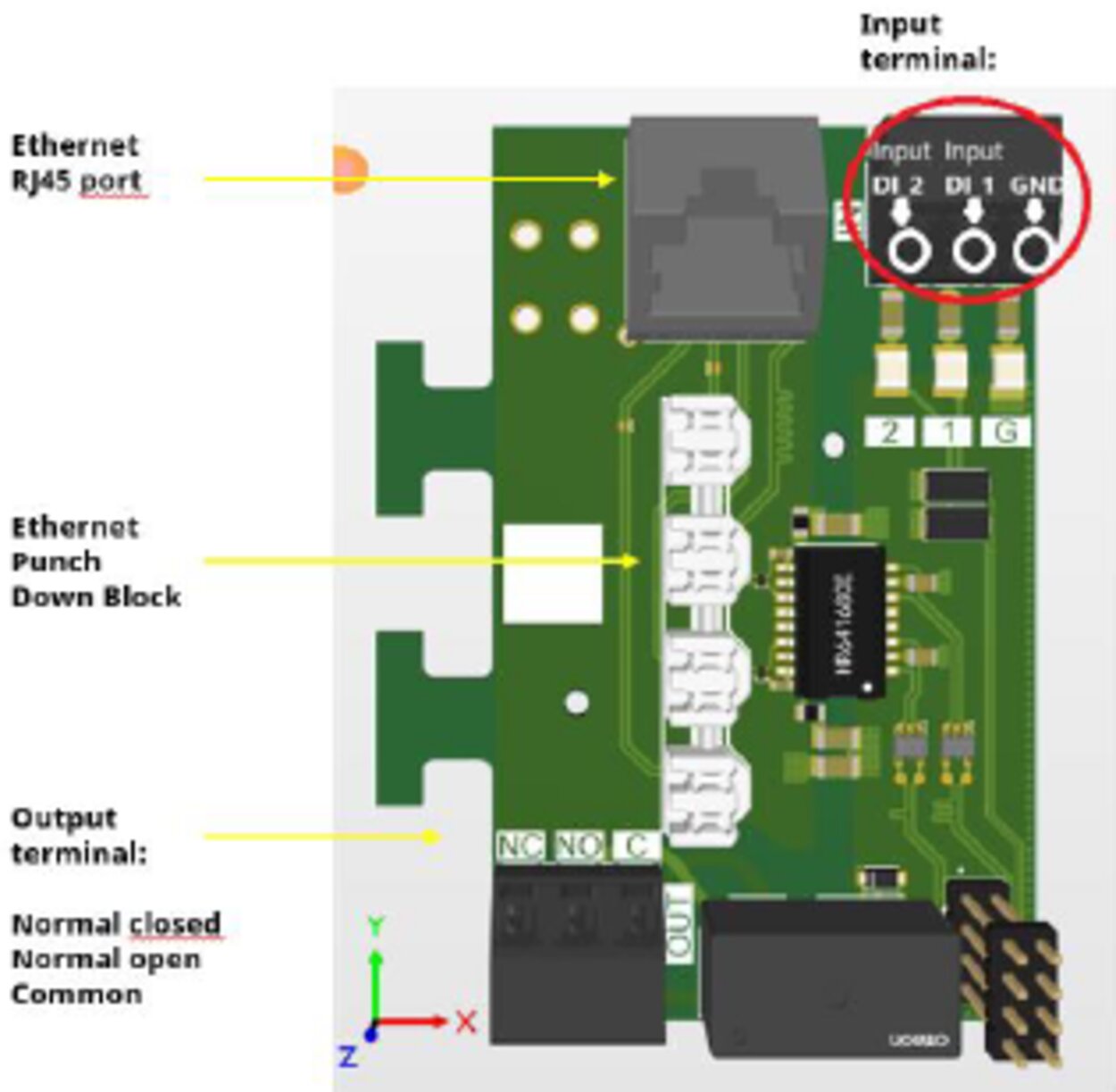
The Fronius Wattpilot Flex is equipped with a digital input (DI_1).
This input in the grid lead limits the charging current. The following use cases are possible:
Only permanently installed switching devices of overvoltage category 3 (in accordance with EN IEC 60664-1) may be used.
Before installation, check that the components used satisfy the corresponding insulation requirements.
Digital input settings are configured in the Solar.wattpilot app (Settings > Digital input) and can be protected with the technician password (Settings > Password > Protect digital input).
The following connection options can be configured in the "Internet" menu:
The following connection options can be configured in the "Internet" menu:
The charging point communication standard OCPP (Open Charge Point Protocol) is a universal communication protocol for charging infrastructures. It enables communication between the Fronius Wattpilot and a management system, via which, for example, the load distribution of an infrastructure or the billing is carried out. Setup is carried out via a remote server provider or locally.
Activate OCPP
Activation or deactivation of OCPP.
Address
The address of the OCPP server must be made available by the provider and entered in the OCPPmenu of the app.
Phase assignment
Make settings for how the phases of the Wattpilot are assigned compared to a smart meter. This is, for example, necessary for the load balancing to function correctly.
User-defined certificate
Option to enter a self-created OCPP certificate.
Alternative ID
If a charging process is started without authentication with an ID chip (Access management > Authentication > Open), an alternative ID that is sent to the backend can be stored.
After confirming the restart, the Wattpilot is restarted; the most recent settings remain saved.
The current firmware of the Wattpilot is loaded via the Internet. The "Internet" menu shows which firmware version is installed and whether an update is available.
The Fronius Solar.wattpilot app can be updated via the respective platform (Google Play Store, App Store).
Beta
If a new beta version of the firmware is provided, you can install and test it in advance. Please send us your feedback on the beta versions.
Changing firmware
The old firmware remains stored on the Wattpilot after an update. In the event of an error, it is also possible to switch between the old and the new firmware version without an Internet connection.
General data | 1-phase | 3-phase |
|---|---|---|
Dimensions (height x width x depth) | 325 x 195 x 105 mm | |
Weight | 4.1 kg | |
Charging cable | 6 m cable, type 2 charging plug | |
Charging cable cross-section | 5 x 2.5 mm² +1 x 0.5 mm² | |
Grid connection | 5‑pin screw terminal | |
Supply line conductor cross-section | Mains cable top (interior), bottom, rear: | |
Nominal current (configurable) | 6 ‑ 16 A | |
Mains frequency | 50 Hz | |
Nominal voltage | 230/240 V | 400/415 V |
Maximum charging power | 3.7 kW | 11 kW |
Grid configurations | TT/TN/IT | |
Standby consumption | 3.5 W | |
Rated impulse withstand voltage | 4 kV | |
Rated insulation voltage | 415 VAC | |
Simultaneity factor | 1 | |
PV optimization1 | Dynamic PV surplus charging from 1.38 - 11 kW (at 230/400 V, automatic 1-/3-phase switching) | |
MID meter | Not integrated | |
Measurement and calibration law compliance | No | |
Charging mode | Mode 3 as per IEC 61851-1 | |
Dynamic Load Balancing | Integrated (unlimited number of charging stations)2 | |
Standards | EN IEC 61851-1, EN 62196, ISO 15118 (prepared on the hardware side) | |
Environmental conditions |
|
|---|---|
Use | Indoors and outdoors3 |
Installation type | Suspended upright |
Ambient temperature | -25 to +45 °C |
Storage temperature | -40 to +85 °C |
Height above sea level | 0 - 2000 m |
Humidity | < 95% (non-condensing) |
Communication interfaces |
|
|---|---|
Interfaces | LAN (RJ45 or LSA) 10/100 Mbit/s |
Communication protocol | OCPP 1.6 J |
WiFi frequency bands and channels | 2412-2472 MHz/1-13 |
WiFi transmission power | < 100 mW (< 20 dBm) |
Authentication | RFID, Solar.wattpilot app |
RFID frequency | 13.56 MHz |
RFID transmission power | max. 60 dBμA/m (10 m) |
Bluetooth | prepared for BLE (2.4 GHz) |
Digital input | 2 non-insulated inputs that can be connected to various devices such as a ripple control receiver |
Digital output | 1 insulated switching contact to support fault isolation or other regulatory requirements. (230 V AC/30 V DC, 5 A) |
Digital input/output cable cross-section | 0.2 - 1.5 mm² |
Power Line Communication | Physical layer in accordance with ISO 15118-3 |
Safety and device protection |
|
|---|---|
Residual current protection device4 | 20 mA AC, 6 mA DC, integrated |
Protective class | 1 |
Overvoltage category | 3 |
Pollution degree | 3 |
EMC emission class (in accordance with IEC 61000-6-2, IEC 61000-6-3) | A+B |
Ingress protection rating | IP 66 |
Impact resistance | IK08 |
General data | 1-phase | 3-phase |
|---|---|---|
Dimensions (height x width x depth) | 325 x 195 x 105 mm | |
Weight | 4.1 kg | |
Charging cable | 6 m cable, type 2 charging plug | |
Charging cable cross-section | 5 x 6 mm² +1 x 0.5 mm² | |
Grid connection | 5‑pin screw terminal | |
Supply line conductor cross-section | Mains cable top (interior), bottom, rear: | |
Nominal current (configurable) | 6 ‑ 32 A | |
Mains frequency | 50 Hz | |
Nominal voltage | 230/240 V | 400/415 V |
Maximum charging power | 7.4 kW | 22 kW |
Grid configurations | TT/TN/IT | |
Standby consumption | 3.5 W | |
Rated impulse withstand voltage | 4 kV | |
Rated insulation voltage | 415 VAC | |
Simultaneity factor | 1 | |
PV optimization1 | Dynamic PV surplus charging from 1.38 - 22 kW (at 230/400 V, automatic 1-/3-phase switching) | |
MID meter | Not integrated | |
Measurement and calibration law compliance | No | |
Charging mode | Mode 3 as per IEC 61851-1 | |
Dynamic Load Balancing | Integrated (unlimited number of charging stations)2 | |
Standards | EN IEC 61851-1, EN 62196, ISO 15118 (prepared on the hardware side) | |
Environmental conditions |
|
|---|---|
Use | Indoors and outdoors3 |
Installation type | Suspended upright |
Ambient temperature4 | -25 to +45 °C |
Storage temperature | -40 to +85 °C |
Height above sea level | 0 - 2000 m |
Humidity | < 95% (non-condensing) |
Communication interfaces |
|
|---|---|
Interfaces | LAN (RJ45 or LSA) 10/100 Mbit/s |
Communication protocol | OCPP 1.6 J |
WiFi frequency bands and channels | 2412-2472 MHz/1-13 |
WiFi transmission power | < 100 mW (< 20 dBm) |
Authentication | RFID, Solar.wattpilot app |
RFID frequency | 13.56 MHz |
RFID transmission power | max. 60 dBμA/m (10 m) |
Bluetooth | prepared for BLE (2.4 GHz) |
Digital input | 2 non-insulated inputs that can be connected to various devices such as a ripple control receiver |
Digital output | 1 insulated switching contact to support fault isolation or other regulatory requirements. (230 V AC/30 V DC, 5 A) |
Digital input/output cable cross-section | 0.2 - 1.5 mm² |
Power Line Communication | Physical layer in accordance with ISO 15118-3 |
Safety and device protection |
|
|---|---|
Residual current protection device5 | 20 mA AC, 6 mA DC, integrated |
Protective class | 1 |
Overvoltage category | 3 |
Pollution degree | 3 |
EMC emission class (in accordance with IEC 61000-6-2, IEC 61000-6-3) | A+B |
Ingress protection rating | IP 66 |
Impact resistance | IK08 |
General data | 1-phase | 3-phase |
|---|---|---|
Dimensions (height x width x depth) | 325 x 195 x 105 mm | |
Weight | 4.1 kg | |
Charging cable | 6 m cable, type 2 charging plug | |
Charging cable cross-section | 5 x 2.5 mm² +1 x 0.5 mm² | |
Grid connection | 5‑pin screw terminal | |
Supply line conductor cross-section | Mains cable top (interior), bottom, rear: | |
Nominal current (configurable) | 6 ‑ 16 A | |
Mains frequency | 50 Hz | |
Nominal voltage | 230/240 V | 400/415 V |
Maximum charging power | 3.7 kW | 11 kW |
Grid configurations | TT/TN/IT | |
Standby consumption | 3.5 W | |
Rated impulse withstand voltage | 4 kV | |
Rated insulation voltage | 415 VAC | |
Simultaneity factor | 1 | |
PV optimization1 | Dynamic PV surplus charging from 1.38 - 11 kW (at 230/400 V, automatic 1-/3-phase switching) | |
Charging mode | Mode 3 as per IEC 61851-1 | |
Dynamic Load Balancing | Integrated (unlimited number of charging stations)2 | |
Standards | EN IEC 61851-1, EN 62196, ISO 15118 (prepared on the hardware side) | |
Measurement |
|
|---|---|
MID meter | Integrated (accuracy class B) |
Measurement and calibration law compliance | Yes |
Pulse constant | 100,000 imp/kWh |
Nominal voltage | 230 V |
Nominal frequency | 230 V 50/60 Hz |
Maximum amperage | 35 A |
Nominal amperage | 7 A |
Starting current | 0.028 A |
Environmental conditions |
|
|---|---|
Use | Indoors and outdoors3 |
Installation type | Suspended upright |
Ambient temperature | -25 to +40 °C |
Storage temperature | -40 to +85 °C |
Height above sea level | 0 - 2000 m |
Humidity | < 95% (non-condensing) |
Communication interfaces |
|
|---|---|
Interfaces | LAN (RJ45 or LSA) 10/100 Mbit/s |
Communication protocol | OCPP 1.6 J |
WiFi frequency bands and channels | 2412-2472 MHz/1-13 |
WiFi transmission power | < 100 mW (< 20 dBm) |
Authentication | RFID, Solar.wattpilot app |
RFID frequency | 13.56 MHz |
RFID transmission power | max. 60 dBμA/m (10 m) |
Bluetooth | prepared for BLE (2.4 GHz) |
Digital input | 2 non-insulated inputs for connecting e.g. a ripple control receiver |
Digital output | 1 insulated switching contact to support fault isolation or other regulatory requirements. (230 V AC/30 V DC, 5 A) |
Digital input/output cable cross-section | 0.2 - 1.5 mm² |
Power Line Communication | Physical layer in accordance with ISO 15118-3 |
Safety and device protection |
|
|---|---|
Residual current protection device4 | 20 mA AC, 6 mA DC, integrated |
Protective class | 1 |
Overvoltage category | 3 |
Pollution degree | 3 |
EMC emission class (in accordance with IEC 61000-6-2, IEC 61000-6-3) | A+B |
Ingress protection rating | IP 66 |
Impact resistance | IK08 |
General data | 1-phase | 3-phase |
|---|---|---|
Dimensions (height x width x depth) | 325 x 195 x 105 mm | |
Weight | 4.1 kg | |
Charging cable | 6 m cable, type 2 charging plug | |
Charging cable cross-section | 5 x 6 mm² +1 x 0.5 mm² | |
Grid connection | 5‑pin screw terminal | |
Supply line conductor cross-section | Mains cable top (interior), bottom, rear: | |
Nominal current (configurable) | 6 ‑ 32 A | |
Mains frequency | 50 Hz | |
Nominal voltage | 230/240 V | 400/415 V |
Maximum charging power | 7.4 kW | 22 kW |
Grid configurations | TT/TN/IT | |
Standby consumption | 3.5 W | |
Rated impulse withstand voltage | 4 kV | |
Rated insulation voltage | 415 VAC | |
Simultaneity factor | 1 | |
PV optimization1 | Dynamic PV surplus charging from 1.38 - 22 kW (at 230/400 V, automatic 1-/3-phase switching) | |
Charging mode | Mode 3 as per IEC 61851-1 | |
Dynamic Load Balancing | Integrated (unlimited number of charging stations)2 | |
Standards | EN IEC 61851-1, EN 62196, ISO 15118 (prepared on the hardware side) | |
Measurement |
|
|---|---|
MID meter | Integrated (accuracy class B) |
Measurement and calibration law compliance | Yes |
Pulse constant | 100,000 imp/kWh |
Nominal voltage | 230 V |
Nominal frequency | 230 V 50/60 Hz |
Maximum amperage | 35 A |
Nominal amperage | 7 A |
Starting current | 0.028 A |
Environmental conditions |
|
|---|---|
Use | Indoors and outdoors3 |
Installation type | Suspended upright |
Ambient temperature4 | -25 to +40 °C |
Storage temperature | -40 to +85 °C |
Height above sea level | 0 - 2000 m |
Humidity | < 95% (non-condensing) |
Communication interfaces |
|
|---|---|
Interfaces | LAN (RJ45 or LSA) 10/100 Mbit/s |
Communication protocol | OCPP 1.6 J |
WiFi frequency bands and channels | 2412-2472 MHz/1-13 |
WiFi transmission power | < 100 mW (< 20 dBm) |
Authentication | RFID, Solar.wattpilot app |
RFID frequency | 13.56 MHz |
RFID transmission power | max. 60 dBμA/m (10 m) |
Bluetooth | prepared for BLE (2.4 GHz) |
Digital input | 2 non-insulated inputs for connecting e.g. a ripple control receiver |
Digital output | 1 insulated switching contact to support fault isolation or other regulatory requirements. (230 V AC/30 V DC, 5 A) |
Digital input/output cable cross-section | 0.2 - 1.5 mm² |
Power Line Communication | Physical layer in accordance with ISO 15118-3 |
Safety and device protection |
|
|---|---|
Residual current protection device5 | 20 mA AC, 6 mA DC, integrated |
Protective class | 1 |
Overvoltage category | 3 |
Pollution degree | 3 |
EMC emission class (in accordance with IEC 61000-6-2, IEC 61000-6-3) | A+B |
Ingress protection rating | IP 66 |
Impact resistance | IK08 |
Wipe the device, if necessary, with a damp cloth.
Do not use cleaning agents, scouring agents, solvents, or similar products to clean the device.
Wipe the device, if necessary, with a damp cloth.
Do not use cleaning agents, scouring agents, solvents, or similar products to clean the device.
Maintenance and service work may only be carried out by a technical specialist.
Waste electrical and electronic equipment must be collected separately and recycled in an environmentally sound manner in accordance with the European Directive and national law. Used equipment must be returned to the distributor or through a local authorized collection and disposal system. Proper disposal of the used device promotes sustainable recycling of resources and prevents negative effects on health and the environment.
Packaging materialsDue to phase, voltage, and switching function checks of the Fronius Wattpilot, a charging operation may be rejected.
The status codes are displayed via the LED status indicator (see LED status indicators on page (→)) directly on the Wattpilot and in the app under "Status".
| Cause: | The residual current device has detected an error. |
| Remedy: | The charging equipment in the vehicle may be defective. Have the charging equipment checked by a specialist. |
| Remedy: | Disconnect and reconnect the charging cable. |
| Cause: | The device is only being supplied with 2 phases. |
| Remedy: | Make sure that phase 2 and phase 3 are connected correctly. Option: a supply via phase 1 only is possible. |
| Cause: | Grounding fault detected. |
| Remedy: | Check that the connection is properly grounded. |
| Cause: | The relay has not switched. |
| Remedy: | Disconnect the power supply to the device for 5 seconds. |
| Cause: | 53 Hz mains current detected. |
| Remedy: | Observe the instructions in the Operating Instructions. |
| Cause: | Device is not sending data. |
| Remedy: | Disconnect and reconnect device. |
| Remedy: | Perform a firmware update. |
| Remedy: | Return device. |
| Cause: | Continuous load. |
| Remedy: | Disconnect device and allow to cool down. |
| Cause: | Incorrectly installed cables. |
| Remedy: | Disconnect device and allow to cool down. |
| Cause: | Flexible electricity tariff cannot be called up. |
| Remedy: | Check WLAN and Internet connection. |
| Remedy | Wait until the server is available again. |
| Cause: | The connection to the inverter cannot be established. |
| Remedy: | Check the network settings. |
| Remedy: | Check the settings of the inverter. |
| Remedy: | Make sure that the Fronius Solar API is activated on the inverter. |
| Cause: | Eco Mode is selected and the "Use PV surplus" and "Use Lumina Strom / aWattar" settings are disabled. |
| Remedy: | Activate the setting "Use PV surplus" and/or "Use Lumina Strom / aWattar". |
| Remedy: | Change the mode. |
| Cause: | "Use Lumina Strom / aWattar" is enabled and there is no data connection to the Internet. Cached price data is still available. |
| Remedy: | Check the network settings. |
| Cause: | The specified time is not sufficient for the desired amount of energy. |
| Remedy: | Extend the specified time for charging. |
| Remedy: | Reduce the desired amount of energy. |
| Cause: | The connection cannot be established. |
| Remedy: | Check the network settings. |
| Cause: | The vehicle is not being detected. |
| Remedy: | Check vehicle cable and fit of charging plugs |
| Cause: | No power on the junction box. |
| Remedy: | Check the overload fuse of the connection. |
| Cause: | The brightness of the LEDs has been set to 0. |
| Remedy: | Increase the brightness of the LEDs in the Fronius Solar.wattpilot app. |
| Cause: | "Switch off LEDs after 10 s in standby" has been enabled. |
| Remedy: | Deactivate "Switch off LEDs after 10 s in standby". |
Detailed warranty conditions specific to your country can be found at www.fronius.com/solar/garantie .
Detailed warranty conditions specific to your country can be found at www.fronius.com/solar/garantie .