Welducation Simulator, Welducation Campus
download
Indicates an immediate danger
Death or serious injury will result if appropriate precautions are not taken.
Indicates a potentially dangerous situation
Death or serious injury may result if appropriate precautions are not taken.
Indicates a potentially harmful situation
Minor injury or damage to property may result if appropriate precautions are not taken.
Indicates a possibility of flawed work results and possible damage to the equipment
The operating instructions must always be kept to hand wherever the device is being used.
In addition to the operating instructions, all applicable local rules and regulations regarding accident prevention and environmental protection must also be followed.
All safety and danger notices on the device:For the location of the safety and danger notices on the device, refer to the section headed "General" in the operating instructions for the device.
Before switching on the device, eliminate any faults that could compromise safety.
Operation or storage of the device outside the stipulated area will be deemed as not in accordance with the intended purpose.
Installation and operation may only take place within closed and dry rooms.
Temperature range of ambient air:
Relative humidity:
Ambient air: free of dust, acids, corrosive gases or substances, etc.
Altitude above sea level: up to 2,000 m (6,500 ft.)
The safety-conscious work of the personnel must be checked regularly.
Before leaving the workplace, ensure that no property damage can occur in their absence.
The mains voltage and mains frequency must match the specifications on the rating plate.
The device must only be connected to a properly installed, secured, and grounded mains socket.
If the device is supplied without a country-specific cable, use the mains plug and cable in accordance with local standards.
An electric shock can be fatal. Only trained and qualified personnel may install and connect the mains plug.
Route the mains cable so that there is no risk of injury (risk of tripping, etc.) and damage to the mains cable.
An electric shock can be fatal.
All cables and leads must be secured, undamaged, insulated, and adequately dimensioned. Replace loose connections and scorched, damaged, or inadequately dimensioned cables and leads immediately.
Do not wrap cables or leads around your body or parts of the body.
Only trained and qualified personnel may carry out repair work (e.g., open the device). If a defect occurs, unplug the device immediately and have the repair carried out by trained and qualified personnel.
This device is an emission class B device.
Devices in emission class B:In certain cases, even though a device complies with the standard limit values for emissions, it may affect the application area for which it was designed (e.g., when there is sensitive equipment at the same location, or if the site where the device is installed is close to either radio or television receivers).
If this is the case, then the operating company is obliged to take appropriate action to rectify the situation.
FOR MOBILE DEVICES (> 20 cm, 7.87 in. / low power)
Explanation of radiation exposure, with the exception of the XR headset:
This device meets the ISED exposure limit values set for an uncontrolled environment. This device should be installed and operated at a distance of more than 20 cm (7.87 in.) between the beam source and your body.
As long as the three conditions described above are satisfied, no further transmitter test is required. However, the OEM integrator remains responsible for testing their final product for any additional compliance requirements that may need to be met with the installed module. The end user manual must contain all necessary regulatory information and warnings as described in these operating instructions.
There is a possibility of electromagnetic interference due to incorrect use of the device.
Impaired radio reception may result.
The device for operation in the 5150-5250 MHz frequency band is only intended for use within closed and dry rooms, in order to reduce the potential for radio interference from co-channel satellite mobile systems.
For devices with detachable antennas, the maximum permissible antenna gain for devices in the 5250-5350 MHz and 5470-5725 MHz bands must be such that the device still complies with the EIRP limit value (only detachable antenna).
For devices with detachable antennas, the maximum permissible antenna gain for devices in the 5725-5850 MHz frequency band must be such that the devices still comply with the corresponding EIRP limit values (detachable antennas only).
If necessary, the type of antenna, the antenna model and the most unfavorable tilt angle required must be clearly indicated, in order to satisfy the requirements for the EIRP elevation mask specified in section 6.2.2.3.
Special regulations apply in areas at risk of fire or explosion.
Carry out a visual inspection of the cables and lines every time the device is started up.
Dimension the mains fuse in accordance with the specifications in the technical data.
Always keep ventilation openings clear. Ensure that the device has an all-round clearance of 0.5 m (19.69 in.).
The ambient temperature during operation may not exceed +40 °C (+104 °F) or drop below -10 °C (+14 °F).
The ambient temperature during transport and storage may not exceed +55 °C (+131 °F) or drop below -20 °C (-4 °F).
Transporting or changing the installation position of the device by pulling on the mains cable is not permitted. Switch off before transporting or lifting.
Do not transport the device by crane. If the device has a manual carrying handle or carrying strap, it is only suitable for manual transport using the carrying handle or strap provided for this purpose.
To avoid back injuries, observe the weight specification in the technical data. If necessary, use a trolley or an appropriate number of people to lift the device.
Risk of personal injury and damage to property due to the device falling or toppling over if set up incorrectly. Only set up the device on a flat, stable surface with the help of trained and qualified personnel.
Do not use the device if you are tired, or under the influence of alcohol, medication or drugs. Carelessness can lead to serious personal injury.
Observe the applicable national and regional guidelines and accident prevention regulations when transporting the device, especially guidelines concerning hazards during transport and shipment.
Only carry out the transport in the original packaging or in the Toolcase provided for this purpose. The original packaging or the appropriate Toolcase can be obtained from the manufacturer.
Do not lift or transport any active devices. Switch off devices before transport or lifting.
Use instructions and checks within the company to ensure that the vicinity of the workplace is always clean and organized.
After transport and before installation and commissioning, it is essential to visually inspect the device for damage. Have trained and qualified personnel repair any damage before installation and commissioning.
The device must be checked at least once a week for externally detectable damage and functionality.
Devices with the CE label satisfy the essential requirements of the low-voltage and electromagnetic compatibility directive (e.g., relevant product standards of the EN 60 974 series).
Fronius International GmbH hereby declares that the radio system of type Welducation Simulator complies with Directive 2014/53/EU. The full text of the EU Declaration of Conformity is available on the following website:
http://www.fronius.com
Devices marked with the CSA test mark satisfy the requirements of the relevant standards for Canada and the USA.
Copyright of these operating instructions remains with the manufacturer.
Text and illustrations were accurate at the time of printing, subject to change.
We are grateful for suggestions for improvement and information on any discrepancies in the operating instructions.
These operating instructions describe the functionality, installation, operation, and maintenance of the Welducation Simulator and the Welducation Campus software.
This document is intended for use by all authorized persons who use the Welducation training concept for teaching or learning welding. The training concept consists of the Welducation Simulator and the Welducation Campus software.
 FCC
FCC
This device conforms to the limit values for a Class B digital device, pursuant to Part 15 of the FCC regulations. These limit values are designed to provide reasonable protection against harmful interference in a residential installation. This device generates and uses high frequency energy and, if not used in accordance with the instructions, may interfere with radio communications. However, there is no guarantee that interference will not occur in a particular installation.
The Welducation Campus software is part of a virtual welding system designed for trainees to learn welding skills. The welding system consists of one or more Welducation Simulators and the separate Welducation Campus software for managing courses and learning content. The AdminTool it contains is used to manage users, devices, and licenses.
The theoretical foundations are learned in the Welducation Campus software, while the practical virtual welding jobs are performed on the Welducation Simulator. The Welducation Campus software is intended for external end devices, such as the supplied Fronius tablet or smartphones, notebooks, and PCs.
It is possible for the trainers to put together a training program tailored to the needs of the trainees. This consists of theory content and exercises on all three welding processes: MIG/MAG, TIG, and MMA. The software provides an overview of the trainees' learning progress and supports assessment.
The software is run on a PC or mobile device, e.g., supplied tablet, notebook or smartphone.
The training concept, consisting of the Welducation Campus software and the Welducation Simulators, is aimed at all authorized teachers and trainees who are involved in teaching or learning the three welding processes MIG/MAG, TIG, and MMA. Another target group is administrators of the Welducation Campus software.
The training concept, consisting of the Welducation Campus software and the Welducation Simulators, is aimed at all authorized teachers and trainees who are involved in teaching or learning the three welding processes MIG/MAG, TIG, and MMA. Another target group is administrators of the Welducation Campus software.
Learning content in the form of documents containing in-house know-how or copyrightable content
Access by unauthorized persons
Make sensitive documents accessible to authorized persons only.
The manufacturer shall not be liable for any lack of or incorrect training success.
The Welducation Campus software, including the AdminTool, must be used exclusively for its intended purpose.
The software is intended for welding simulation only with the included hardware.
Any other use shall be deemed to be not in accordance with the intended use.
Intended use also means:The Welducation Campus software, including the AdminTool, must be used exclusively for its intended purpose.
The software is intended for welding simulation only with the included hardware.
Any other use shall be deemed to be not in accordance with the intended use.
Intended use also means:The device is to be used exclusively for its intended purpose and in accordance with the user concept.
The device is exclusively intended for welding simulation with the software and hardware supplied by the manufacturer.
Utilization for any other purpose, or in any other manner shall be deemed improper.
The manufacturer shall not be liable for any resulting damage.
The device is designed for operation in closed and dry rooms. The manufacturer shall not be liable for any damage resulting from use in other environments.
The manufacturer shall not be liable for any lack of or incorrect training success.
All system components that are used in connection with the training concept are only suitable for training purposes and are not intended for real welding.
Make sure that the Welducation Simulator and all components connected to it are only ever used within their permitted operating range.
With regard to data protection, the provisions of the GDPR (General Data Protection Regulation) apply.
The manufacturer's data privacy statement is available at https://www.fronius.com/en-us/usa/privacy-statement
When using the Welducation Campus software, follow the safety instructions in these operating instructions.
The customer is responsible for:Default password
Inadequate protection due to default password for logging into the AdminTool or into the Welducation Campus software
The default password is only provided for the first login.
Change the default password to prevent unauthorized access or tampering.
When creating the password, comply with the following guideline:
at least 8 characters, upper and lower case letters
at least 1 number and 1 special character
no accents
Executing learning content
Avoid injuries and inadequate learning outcomes as follows:
During the first exercises, it is recommended to work while seated in order to accommodate the changed perception of the room environment when wearing the XR headset.
Read and follow all safety instructions in the operating instructions for the Welducation Simulator and the Welducation Campus software.
As a result of updates, your software may contain functions that are not described in these operating instructions. In addition, individual figures may differ slightly from the operating elements of your software. These operating elements function in exactly the same way, however.
Detailed information on software updates can be found in the chapter "Welducation Campus software—operation", section Device Management.

| (1) | Workpieces |
| (2) | XR headset |
| (3) | Welding torch or electrode holder |
| (4) | Welducation Simulator |
| (5) | Return lead cable |
| (6) | Fronius tablet with case |
| (7) | Table stand with magnetic holder |
| (1) | Workpieces |
| (2) | XR headset |
| (3) | Welding torch or electrode holder |
| (4) | Welducation Simulator |
| (5) | Return lead cable |
| (6) | Fronius tablet with case |
| (7) | Table stand with magnetic holder |
The Welducation Simulator largely corresponds to a real welding machine in terms of its appearance, operation, interfaces, and connections. As such, the focus is not only on welding, but also on the preparatory activities.
The XR headset is used to visualize the welding simulation. The XR headset operates according to the principle of augmented reality. The trainees see the welding torch or the stick electrode together with the arc and the workpiece with the resulting weld as an animation. To aid orientation, the environment is displayed as a real camera image, e.g., of the user's own hands.

The XR headset is equipped with an optical camera and an additional stereo camera for recording and integrating the virtually displayed objects.
The standard equipment of the Welducation Simulator offers a wide range of welding scenarios. In addition to the MIG/MAG, TIG, and MMA welding processes that can be learned with the simulator, the variety of supplied virtual workpieces ensures the trainees receive varied, practical training.
In order to practice welding as realistically as possible, it was important to also reproduce the system components as faithfully as possible. This means that the welding torch and electrode holder correspond to their real-life role model in terms of haptics and weight.
Both the welding torch or the electrode holder and the return lead cable for the workpiece are connected as they would be in a real welding situation.


Simulation of common welding processes by means of the following components:


Workpieces:

T-joint, fillet weld

Corner weld

Lap joint

Butt weld

Pipe connection
Pipe-to-plate connectionThe following workpiece properties can be simulated:
To practice a wide variety of welding positions:

Table stand with magnetic holder to fix the workpieces in any position
For ergonomic operation when wearing the XR headset:

External visualization:

Warning notices and safety symbols are located on the device. Removing or painting over the warning notices and safety symbols is not permitted. They warn against incorrect operation.

Safety symbols: | |
 | Dispose of defective devices in accordance with safety rules and not in normal domestic waste. |
 | Possibility of minor injury and property damage due to incorrect operation. |
 | Incorrect operation and incorrectly performed work can cause minor injury and property damage. Only trained and qualified personnel may perform installation, repair, and maintenance work. Read and understand these operating instructions in full. |
 | Devices with the CE label satisfy the essential requirements of the low-voltage and electromagnetic compatibility directives. |
 | Devices with the UKCA label satisfy the essential requirements of the applicable directives of the United Kingdom. |
 | Devices with the FCC label conform to the limit values for a Class B digital device, pursuant to Part 15 of the FCC regulations. This device conforms to the limit values for a Class B digital device, pursuant to Part 15 of the FCC regulations. These limit values are designed to provide reasonable protection against harmful interference in a residential installation. This device generates and uses high frequency energy and, if not used in accordance with the instructions, may interfere with radio communications. However, there is no guarantee that interference will not occur in a particular installation. If this device does cause harmful interference to radio or television reception, which can be determined by turning the device off and on again, the user is encouraged to try to correct the interference using one or more of the following measures:
|
 | Part 15 of the FCC regulations is subject to the following 2 conditions:
|
Because of updates, certain functions may be available on your device but not described in these operating instructions. In addition, individual figures may also differ slightly from the operating elements of your device.

| (1) | Ventilation openings: Device cooling |
| (2) | MIG/MAG welding torch connection: For connecting the MIG/MAG welding torch |
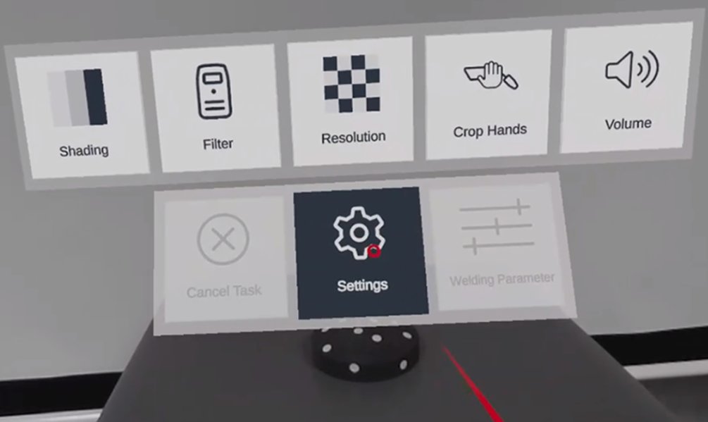
| (3) | Storage tray: e.g., for storing the XR headset and interaction target Holder for the welding torch or electrode holder |
| (4) | Shielding gas simulation: Knob to simulate the adjustment of the shielding gas quantity by means of a gas pressure regulator The value is displayed in the Welducation Campus software. |
| (5) | Green, yellow, and red status LEDs *) |
| (6) | TMC connection (TIG Multi Connector): To connect a TIG welding torch with TIG Multi Connector |
| (7) | (+) current socket with bayonet latch: To connect the return lead cable for TIG welding To connect the electrode cable or return lead cable for manual metal arc welding (depending on the type of electrode used) |
| (8) | (-) current socket with bayonet latch: To connect the return lead cable for MIG/MAG welding To connect a standard TIG welding torch To connect the electrode cable or return lead cable for manual metal arc welding (depending on the type of electrode used) |
*) LED | Status |
|---|---|
No indicator lights up | Simulator is switched off |
Green flashes quickly | Simulator powering up |
Green lights up | Simulator is fully powered up and ready for operation |
Green and yellow light up | Job is running on Simulator |
Yellow lights up and yellow flashes slowly | Error |
Yellow flashes slowly | No network available |
Green flashes quickly and yellow lights up | Start/stop 3D simulation |
Green flashes slowly and yellow lights up | 3D simulation is running |
Green, yellow and yellow again flash alternately in succession | Update in progress |
To ensure a flawless network connection: If set, disable PoE (Power over Ethernet) on the relevant switch port.

| (9) | Network connection: LAN (RJ45) |
| (10) | HDMI port: For external displays, such as projectors and monitors |
| (11) | USB port: To charge a tablet To export data Service interface |
| (12) | Power switch: To switch the Welducation Simulator on and off |
| (13) | WiFi antenna |
| (14) | Mains cable connection |

| (15) | Knurled screw To secure the MIG/MAG welding torch |
| (1) | Ventilation openings: Device cooling |
| (2) | MIG/MAG welding torch connection: For connecting the MIG/MAG welding torch |
| (3) | Storage tray: e.g., for storing the XR headset and interaction target Holder for the welding torch or electrode holder |
| (4) | Shielding gas simulation: Knob to simulate the adjustment of the shielding gas quantity by means of a gas pressure regulator The value is displayed in the Welducation Campus software. |
| (5) | Green, yellow, and red status LEDs *) |
| (6) | TMC connection (TIG Multi Connector): To connect a TIG welding torch with TIG Multi Connector |
| (7) | (+) current socket with bayonet latch: To connect the return lead cable for TIG welding To connect the electrode cable or return lead cable for manual metal arc welding (depending on the type of electrode used) |
| (8) | (-) current socket with bayonet latch: To connect the return lead cable for MIG/MAG welding To connect a standard TIG welding torch To connect the electrode cable or return lead cable for manual metal arc welding (depending on the type of electrode used) |
*) LED | Status |
|---|---|
No indicator lights up | Simulator is switched off |
Green flashes quickly | Simulator powering up |
Green lights up | Simulator is fully powered up and ready for operation |
Green and yellow light up | Job is running on Simulator |
Yellow lights up and yellow flashes slowly | Error |
Yellow flashes slowly | No network available |
Green flashes quickly and yellow lights up | Start/stop 3D simulation |
Green flashes slowly and yellow lights up | 3D simulation is running |
Green, yellow and yellow again flash alternately in succession | Update in progress |
To ensure a flawless network connection: If set, disable PoE (Power over Ethernet) on the relevant switch port.
| (9) | Network connection: LAN (RJ45) |
| (10) | HDMI port: For external displays, such as projectors and monitors |
| (11) | USB port: To charge a tablet To export data Service interface |
| (12) | Power switch: To switch the Welducation Simulator on and off |
| (13) | WiFi antenna |
| (14) | Mains cable connection |
| (15) | Knurled screw To secure the MIG/MAG welding torch |
Necessary network settings must be made by IT administrators, for example, in a company network.
Detailed information can be found in the section Cloud commissioning.
Necessary network settings must be made by IT administrators, for example, in a company network.
Detailed information can be found in the section Cloud commissioning.
Necessary network settings must be made by IT administrators, for example, in a company network.
Detailed information can be found in the section Cloud commissioning.
The default delivery state is always Offline Standalone.
Online Cloud must be set up separately.
Possibility of incorrect operation or work carried out incorrectly
This can result in minor injury and damage to property.
Only trained and qualified personnel are permitted to perform all work and functions described in this document, in accordance with the applicable national and international standards.
Read and understand the operating instructions, especially the safety rules.
Follow the setup regulations.
Possibility of devices or system components toppling or falling
This can result in minor injury and damage to property.
Set up the Welducation Simulator, the stands, and all system components in a stable position.
Ensure the interaction target and virtual workpieces are held securely in place.
Possibility of impermissible environmental conditions
The system is designed for operation in residential or commercial environments. Operation in industrial environments may result in malfunctions. This can result in damage to property.
It is essential to observe the following information.
Possibility of partially covered air intake and outlet openings.
This can result in damage to property.
Ensure that the device has an all-round clearance of 0.5 m (19.69 in.).
Ensure that the permissible environmental conditions are maintained at all times.
Special regulations apply in areas at risk of fire or explosion – follow the appropriate national and international regulations.
Possibility of poor acclimatization of components by connecting the device to the grid too early
May result in damage to the device.
Do not connect the device to the grid and switch it on until 4 hours after the setup has been completed.
The device is designed for the mains voltage stated on the rating plate. Fuse protection for the mains lead can be found in the technical data.
Possibility of electric shock due to damaged grid leads.
An electric shock can cause injury and damage to property.
Carry out a visual inspection of all cables and lines every time the Welducation Simulator is started up.
A short circuit / arc on the device may cause a fire hazard.
Possibility of injury or damage to property due to fire or burns.
Dimension the mains fuse in accordance with the specifications in the technical data.
Possibility of inadequately dimensioned electrical installation
This can result in damage to property.
The mains lead and its fuse protection should be designed to suit the existing mains supply.
The technical data on the rating plate applies.

Before switching on the Welducation Simulator:

Before switching on the Welducation Simulator:
Possibility of objects falling or toppling
Toppling or falling objects may cause minor injuries and damage to property.
Choose a load-bearing and level table / surface on which to set up the table stand.
Set up the table stand in such a way that it is held securely and cannot topple or fall down.
After the adjustment process, tighten the adjusting screws on the table stand so that the stand is stable and able to support a load.
When positioning the workpiece on the magnetic holder of the table stand, ensure that the workpiece rests flush against the magnet.
Ensure that the terminal clamp for the return lead cable is securely seated.
The table stand comes complete with a magnetic holder. The workpiece is held magnetically on the magnetic holder of the table stand. The terminal clamp for the return lead cable is attached in a suitable place on the table stand.
Possibility of objects falling or toppling
Toppling or falling objects may cause minor injuries and damage to property.
When positioning the workpiece on the magnetic holder, ensure that the workpiece rests flush against the magnet.
Possibility of objects falling or toppling
Toppling or falling objects may cause minor injuries and damage to property.
When positioning the workpiece on the magnetic holder, ensure that the workpiece rests flush against the magnet.
Used to secure the virtual workpiece to the stand for the optional Basic welding table
Possibility of objects falling or toppling
Toppling or falling objects may cause minor injuries and damage to property.
Choose a load-bearing and level surface on which to set up the stand.
Set up the stand in such a way that it is held securely and cannot topple or fall down.
After the adjustment process, tighten the fastening screw for the installation and the adjusting screws on the stand so that the stand is stable and able to support a load.
When positioning the workpiece on the magnetic holder of the stand, ensure that the workpiece rests flush against the magnet.
Ensure that the terminal clamp for the return lead cable is securely seated.

| (1) | Magnetic holder |
| (2) | Stand |
| (3) | Base |
| (4) | Allen screw |
| (5) | Allen key |
The stand comes complete with a magnetic holder. The workpiece is held magnetically on the magnetic holder of the stand. The terminal clamp for the return lead cable is attached in a suitable place on the stand.
The stand offers the following positions and setting options:Danger from electrical current
This may result in serious injuries or death.
Only use the supplied mains cable to connect to the grid.
Only connect the mains cable to a properly grounded socket.
Possibility of poor acclimatization of components by connecting the device to the grid too early
May result in damage to the device.
Do not connect the device to the grid and switch it on until 4 hours after the setup has been completed.
Possibility of insufficient or non-existent power supply to the device as a result of a not fully engaged mains cable
The device may remain inoperative after being switched on or may fail during operation.
When connecting the mains cable to the Welducation Simulator as explained below, make sure that the mains cable audibly clicks into place at the connection on the Welducation Simulator.

Danger from electrical current
This may result in serious injuries or death.
Only use the supplied mains cable to connect to the grid.
Only connect the mains cable to a properly grounded socket.
Possibility of poor acclimatization of components by connecting the device to the grid too early
May result in damage to the device.
Do not connect the device to the grid and switch it on until 4 hours after the setup has been completed.
Possibility of insufficient or non-existent power supply to the device as a result of a not fully engaged mains cable
The device may remain inoperative after being switched on or may fail during operation.
When connecting the mains cable to the Welducation Simulator as explained below, make sure that the mains cable audibly clicks into place at the connection on the Welducation Simulator.
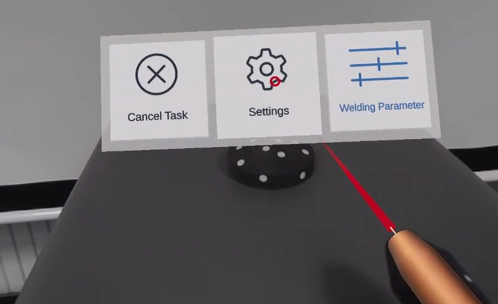
The Welducation Simulator is operated via the Welducation Campus software. This also applies to the settings listed below for the respective welding processes. Information on this can be found in the following chapters.
Possibility of objects falling or toppling
Toppling or falling objects may cause minor injuries and damage to property.
Choose a load-bearing and level table / surface on which to set up the stand.
Set up the stand in such a way that it is held securely and cannot topple or fall down.
After the adjustment process, tighten the adjusting screws on the stand so that the stand is stable and able to support a load.
When positioning the workpiece, ensure that the workpiece rests flush against the magnet.
Ensure that the terminal clamp for the return lead cable is securely seated.
Ensure the interaction target is held securely in place.


Possibility of the welding torch being only partially inserted
This can result in damage to property.
After inserting the welding torch, ensure it is in the correct end position.

Possibility of an insufficiently secured welding torch
This can result in damage to property.
Double check that the welding torch is pushed in as far as it will go.
Tighten the knurled screw for the welding torch to a torque of 3 Nm.


Possibility of the welding torch being only partially inserted
This can result in damage to property.
After inserting the welding torch, ensure it is in the correct end position.
Possibility of an insufficiently secured welding torch
This can result in damage to property.
Double check that the welding torch is pushed in as far as it will go.
Tighten the knurled screw for the welding torch to a torque of 3 Nm.


"Special 4-step mode" takes into account the high thermal conductivity of aluminum and is suitable for welding aluminum materials.

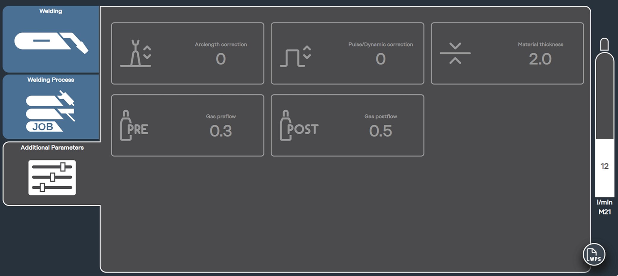
GPr
Gas pre-flow time
I-S
Starting-current phase: rapid heating of the base material despite high heat dissipation at the start of welding
t-S
Starting current duration
S
Start arc length correction parameter:
Arc length correction at the start of welding
SL1
Slope 1: continuous reduction of the starting current to the welding current
IWelding current phase: even heat input into the parent material whose temperature is raised by the advancing heat
I-E
Final current phase: to avoid local overheating of the base material caused by heat accumulation at the end of welding. This prevents possible sagging of the weld.
t-E
Final current duration
E
End arc length correction parameter:
Arc length correction at the end of welding
SL2
Slope 2: continuous reduction of the welding current to the final current
GPo
Gas post-flow
The MIG/MAG standard manual welding process is a MIG/MAG welding process with no synergic function.
Changing one parameter does not result in any automatic adjustments to the other parameters. All variable parameters can be set individually.
The MIG/MAG standard manual welding process is a MIG/MAG welding process with no synergic function.
Changing one parameter does not result in any automatic adjustments to the other parameters. All variable parameters can be set individually.

The Welducation Simulator is ready.
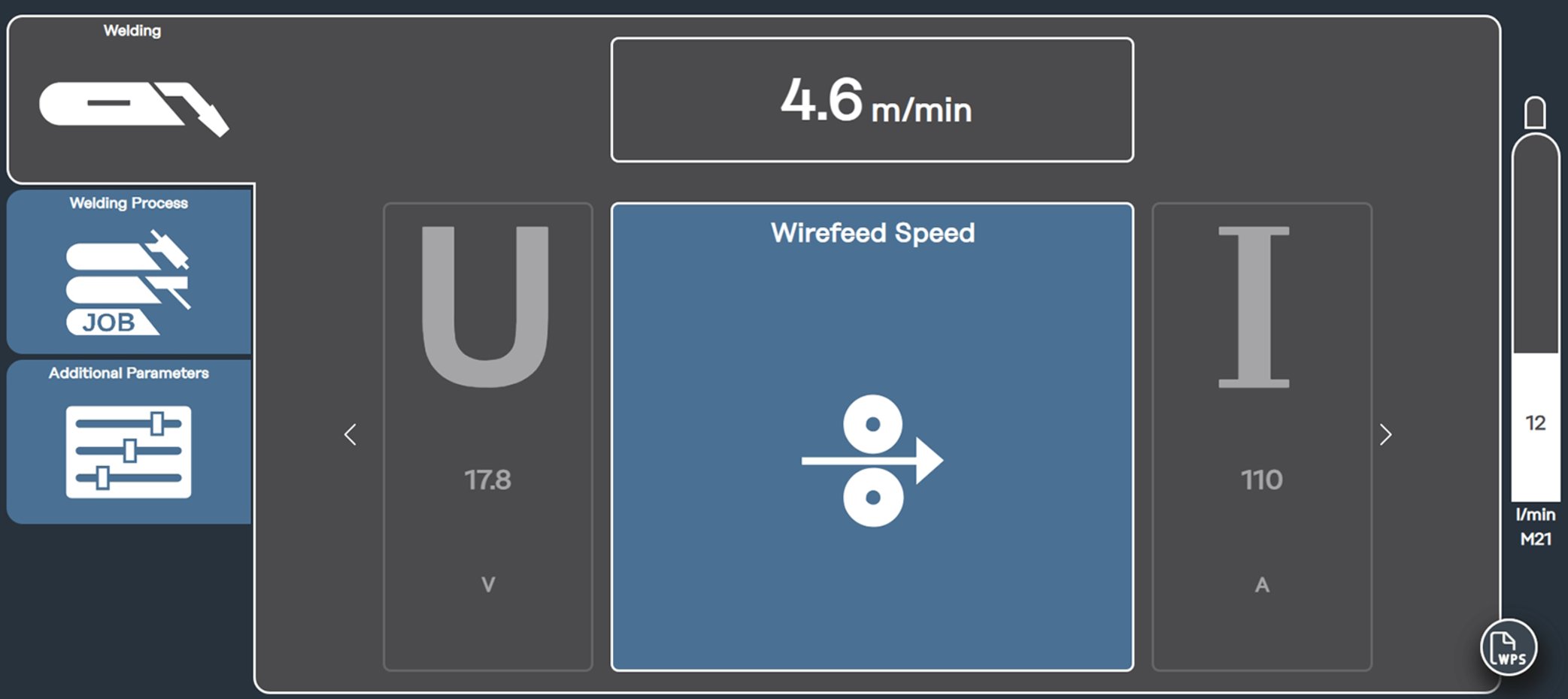
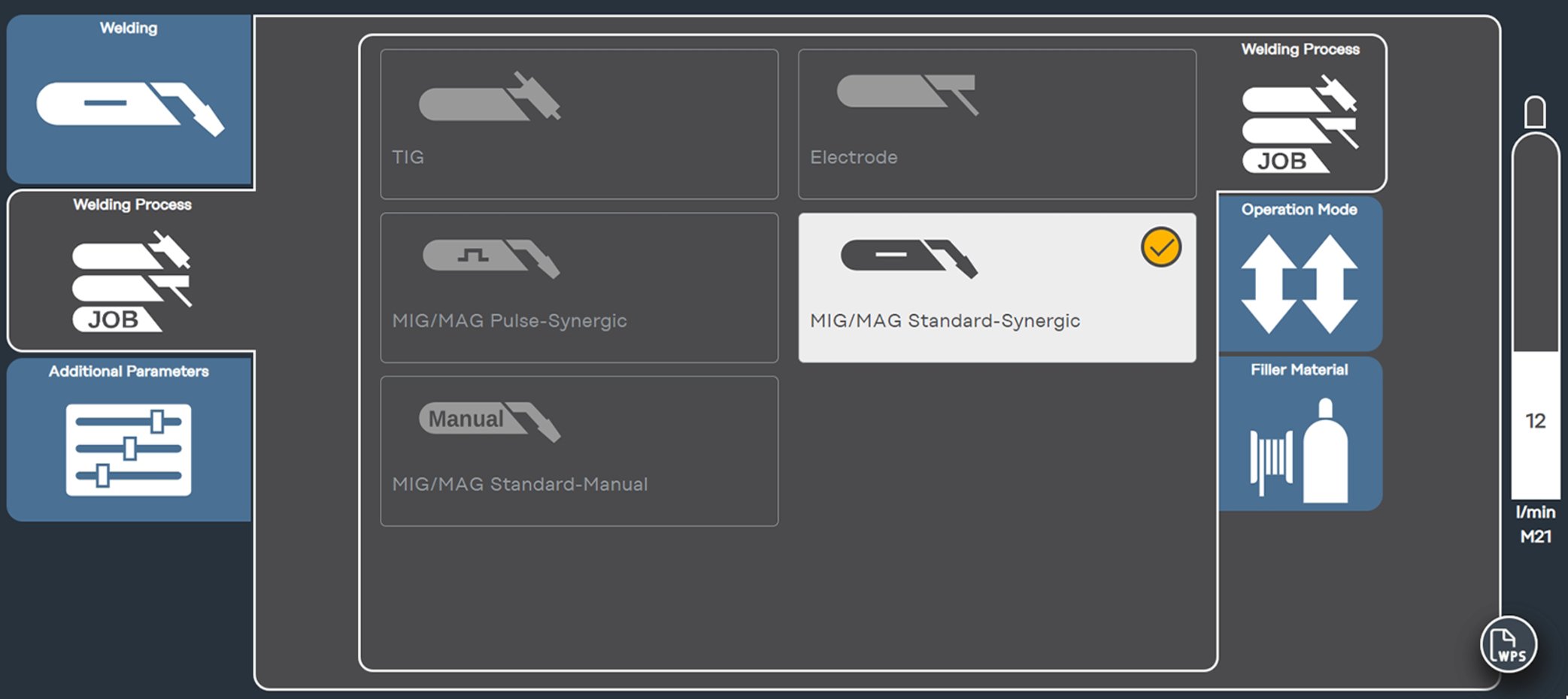
The MIG/MAG synergic welding process is a MIG/MAG welding process with synergic function.
Changing one parameter results in automatic adjustment of the other parameters. The welding power can optionally be specified by means of one of the following parameters:
The MIG/MAG synergic welding process is a MIG/MAG welding process with synergic function.
Changing one parameter results in automatic adjustment of the other parameters. The welding power can optionally be specified by means of one of the following parameters:
The Welducation Simulator is ready.


The Welducation Simulator is ready.


GPr | Gas pre-flow |
IS | Starting current: |
IE | Final current: |
tUP | UpSlope: |
tDOWN | DownSlope: |
I1 | Main current (welding current): |
I2 | Lowering current: |
GPO | Gas post-flow |
GPr | Gas pre-flow |
IS | Starting current: |
IE | Final current: |
tUP | UpSlope: |
tDOWN | DownSlope: |
I1 | Main current (welding current): |
I2 | Lowering current: |
GPO | Gas post-flow |

*) Intermediate lowering
With intermediate lowering, the welding current is lowered to the set lowering current I-2 during the main current phase.

In reality, information on whether the stick electrode is for (+) or (-) welding can be found on the stick electrode packaging.
With the Welducation Simulator, the supplied stick electrode can be used for all available scenarios on (+) and (-).

In reality, information on whether the stick electrode is for (+) or (-) welding can be found on the stick electrode packaging.
With the Welducation Simulator, the supplied stick electrode can be used for all available scenarios on (+) and (-).
The Welducation Simulator is ready.
Both applications can be used with the supplied Fronius tablet. Other end devices (smartphones, notebooks, PCs, etc.) are possible for the "Cloud" operating mode. Only use the Fronius tablet for "Standalone" operating mode.

"Standalone" operating mode of the Welducation Campus software:

The AdminTool cannot be started directly on the tablet, As such, you will need to switch from Campus to the AdminTool in the drop-down menu as shown.
Both applications can be used with the supplied Fronius tablet. Other end devices (smartphones, notebooks, PCs, etc.) are possible for the "Cloud" operating mode. Only use the Fronius tablet for "Standalone" operating mode.
"Standalone" operating mode of the Welducation Campus software:
The AdminTool cannot be started directly on the tablet, As such, you will need to switch from Campus to the AdminTool in the drop-down menu as shown.
The following operating modes are provided for the interaction between the Welducation platform and the Welducation Simulators:
Note: Data are not synchronized between the individual operating modes.
The following operating modes are provided for the interaction between the Welducation platform and the Welducation Simulators:
Note: Data are not synchronized between the individual operating modes.
The Welducation platform runs on the end device (Fronius tablet) as a standalone solution for managing the Welducation Simulators, users, courses, or even for completing the courses.
Standalone (OFFLINE) is included as a basic variant in the standard scope of supply and is always available.
The Welducation platform runs on a cloud server. In order to use this operating variant, Internet access is required for the end device (Fronius tablet, smartphone, notebook, PC, etc.) and the Welducation Simulators. The "Cloud" (ONLINE) operating variant allows the user to complete all tasks that are not linked to the Welducation Simulators independently of location (manage courses/content, complete courses—e.g., theory).
There may be a slightly delayed reaction with all of the actions explained below. For this reason, when pressing a button, you should wait until the corresponding LED lights up.

| Role | AdminTool | Campus | Remarks |
|---|---|---|---|---|
| Admin |  |  |
|
Trainer | | |
| |
Campus Students | | |
|
Access to the Welducation platform depends on which operating mode has been selected.
The Welducation Simulator factory setting is "Standalone".
Access to the Welducation platform depends on which operating mode has been selected.
The Welducation Simulator factory setting is "Standalone".
The following steps are required to access the Fronius tablet for the first time:
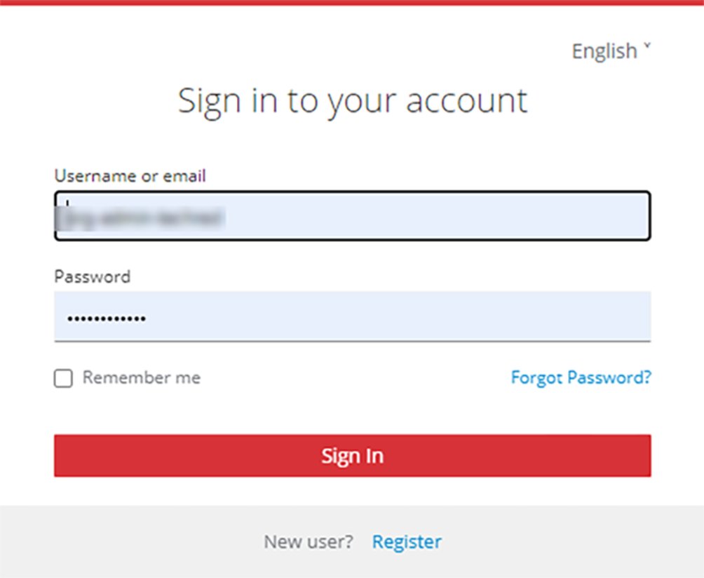
IMPORTANT: Username and password are intended for the administrator.
Other users (regardless of role) register themselves on the Welducation Simulator.
IMPORTANT: Each self-registered user is initially assigned the role of "Campus Student".
A Fronius tablet is not required for commissioning the "Cloud" operating mode. The Welducation Simulator must be switched on.
E-mail address for cloud requests:IMPORTANT: The administrator user data (username and password) are unique and must be kept secure. Password guidelines: at least 8 characters, upper and lower case letters, at least 1 number and 1 special character. No characters with accents!
The administrator now has the option to invite the trainers to the organization via e-mail.

IMPORTANT: Each self-registered user is initially assigned the role of "Campus Student".
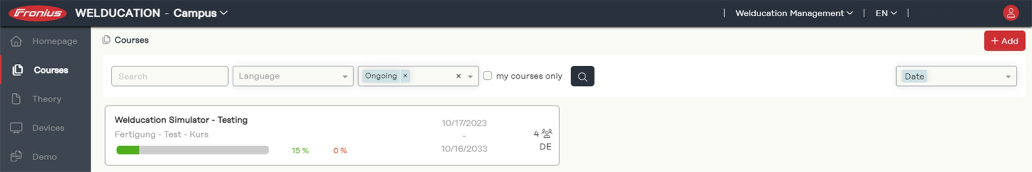
The timing and content of planned courses can be adjusted prior to the start of the course.
The end date can be adjusted for ongoing courses.
No action can be taken for past courses.
The timing and content of planned courses can be adjusted prior to the start of the course.
The end date can be adjusted for ongoing courses.
No action can be taken for past courses.
The timing and content of planned courses can be adjusted prior to the start of the course.
The end date can be adjusted for ongoing courses.
No action can be taken for past courses.
An explanation of how a course template can be created can be found in the section Course templates.
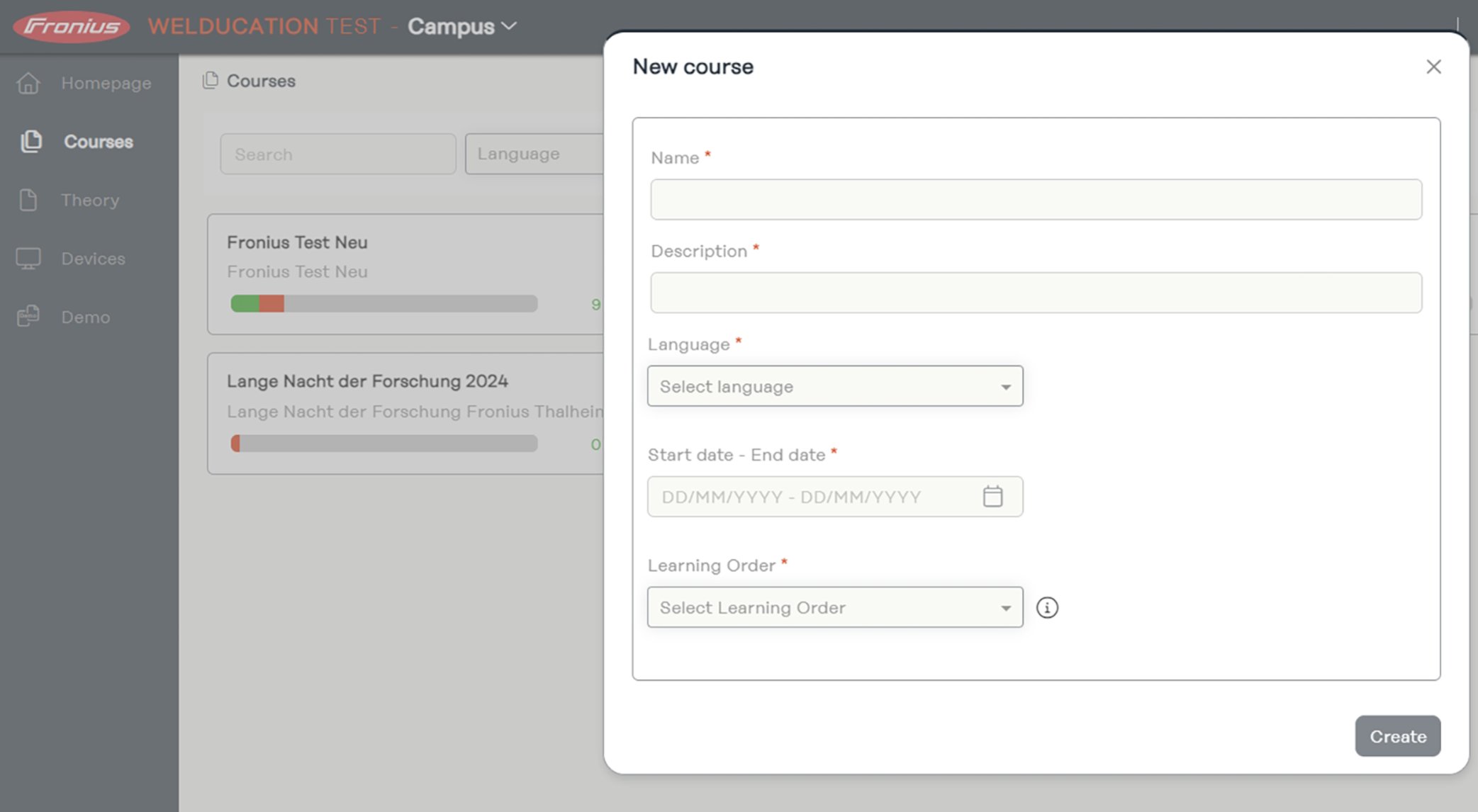
Whether created from scratch or based on a course template:
The trainer must first add a learning module before they can add learning content ("+ Add content"):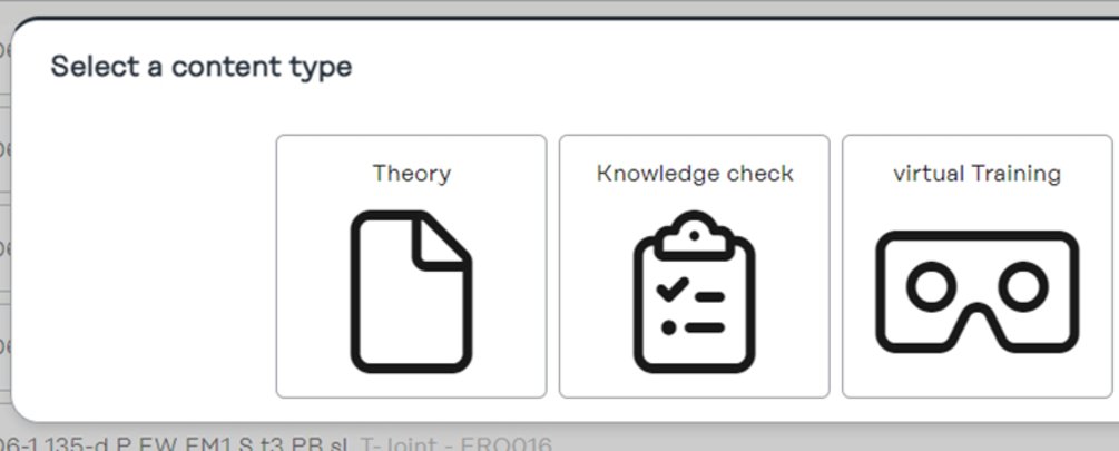
To add learning content within a course:
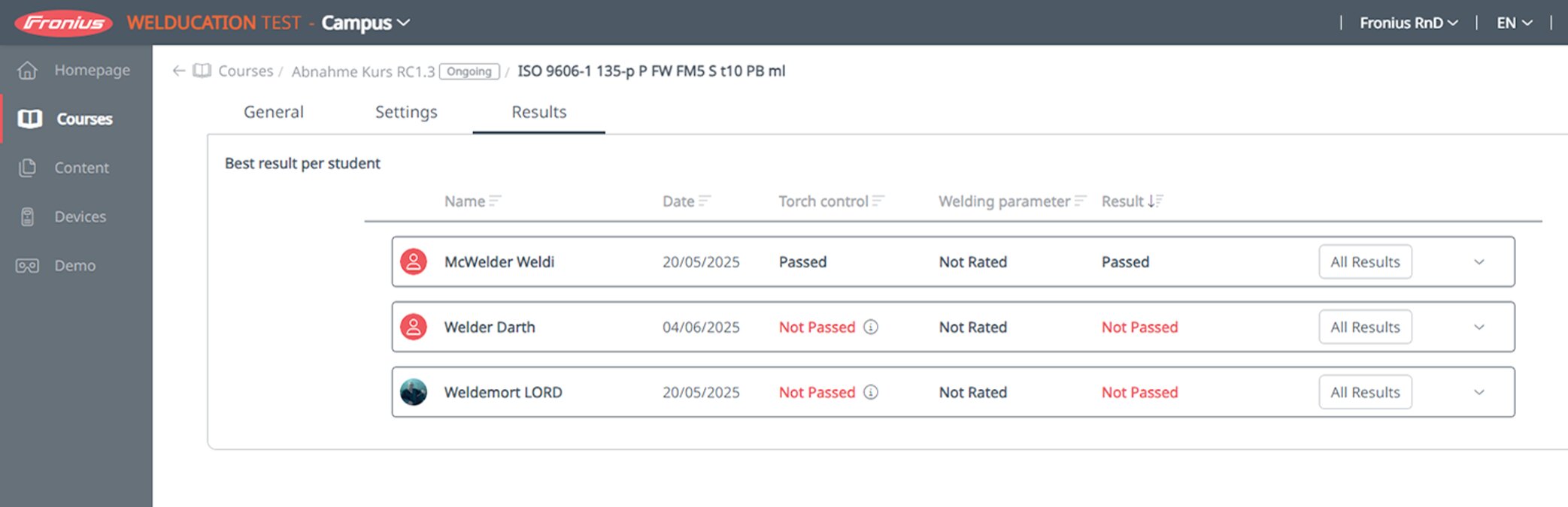
When completing a course, students are assessed as "Campus Students" and trainers are not assessed.
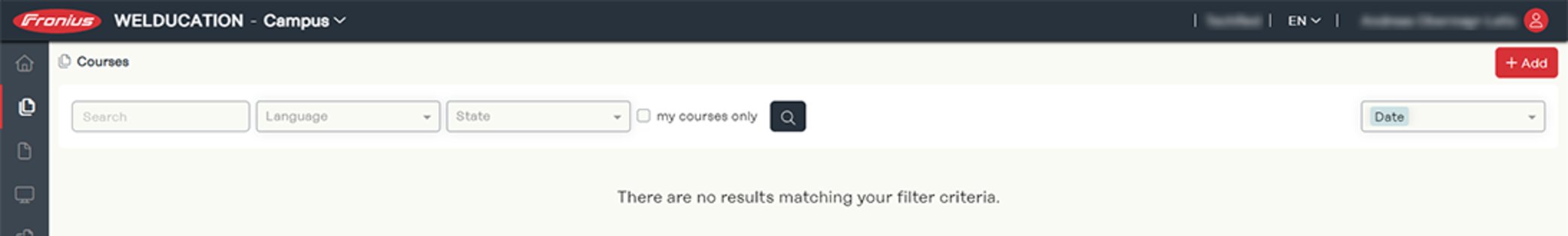
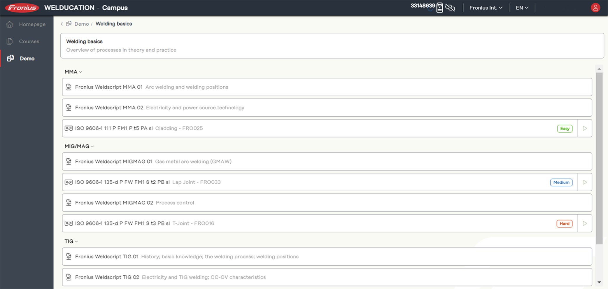
In the course overview, students see the content assigned to them and their progress.
Virtual welding jobs can be found in the course overview under the heading of the corresponding welding process, e.g. "MAG".
Virtual welding jobs are practical exercises that the student carries out on the Welducation Simulator.
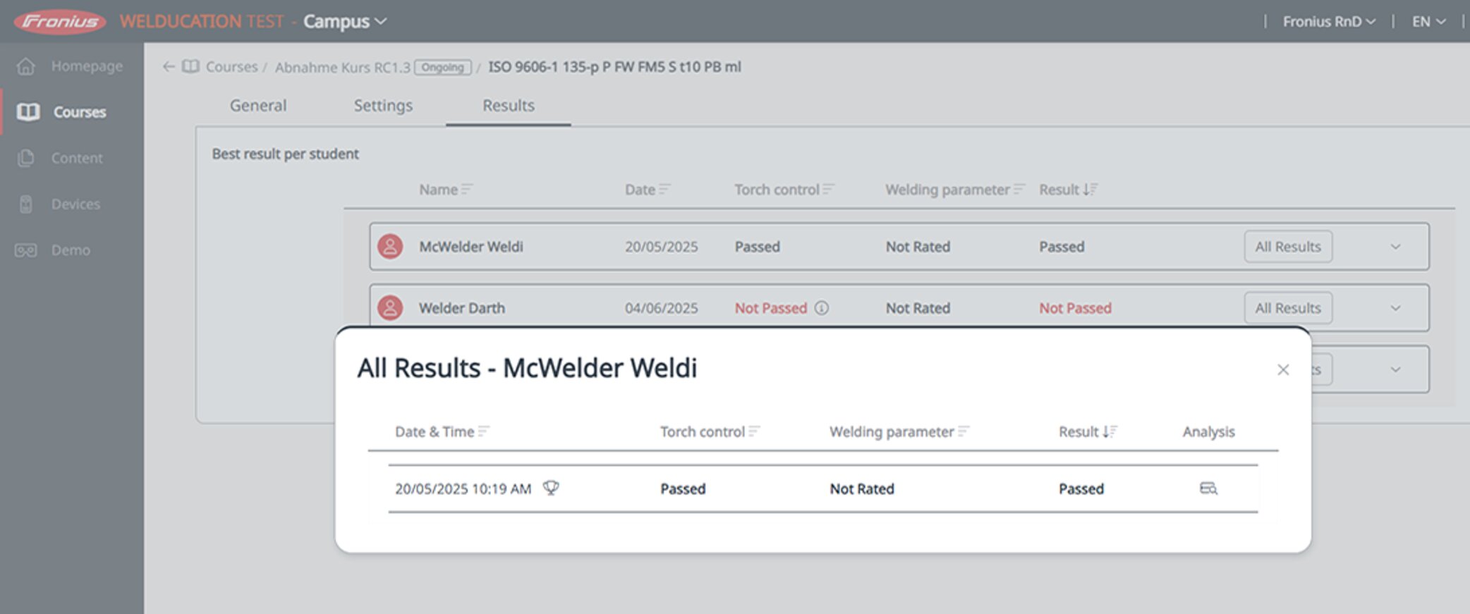
The students see their progress on the course or in the relevant task. The trainer sees the progress of all students on the course.
The checklist and parameter settings depend on the level selected.
The "Next" button takes you to the parameter settings:
Different settings may be required depending on the level.
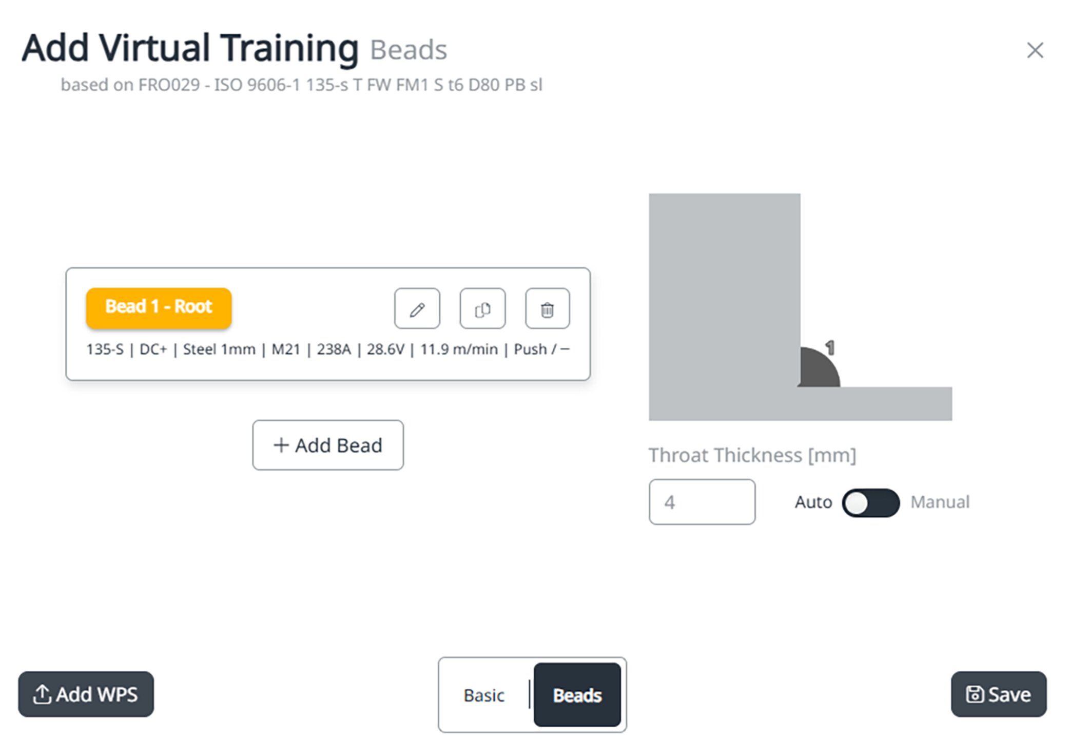
Note: The details of the welding job can be viewed under WPS.
WPS stands for "Welding Parameter Settings": Welding parameter settings
In addition to setting the parameters in the Campus software, there is the option of adjusting the welding parameters in the virtual job.
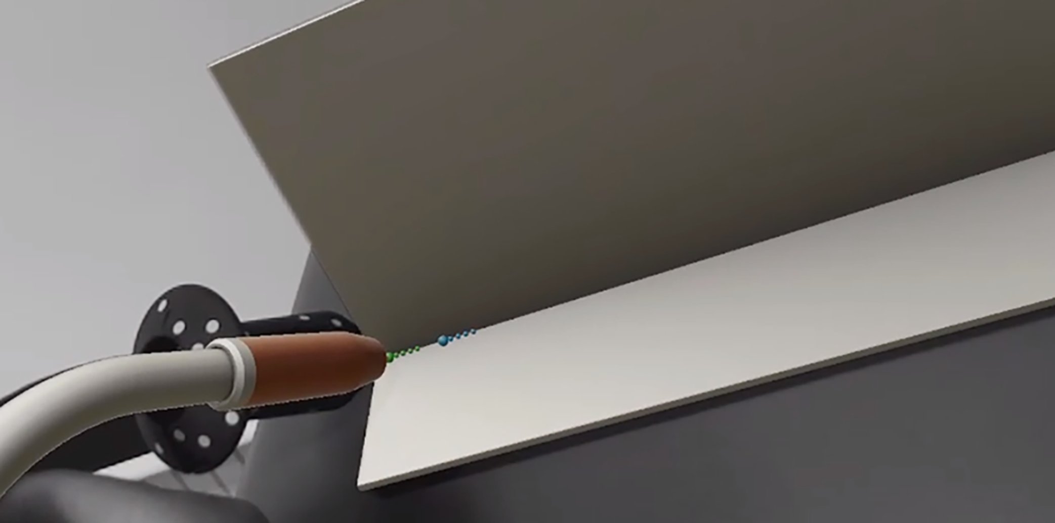
In the "Easy" and "Medium" levels, the ghost is displayed as an aid during welding. In the "Medium" level, the ghost only appears if guidance of the welding torch needs to be corrected.
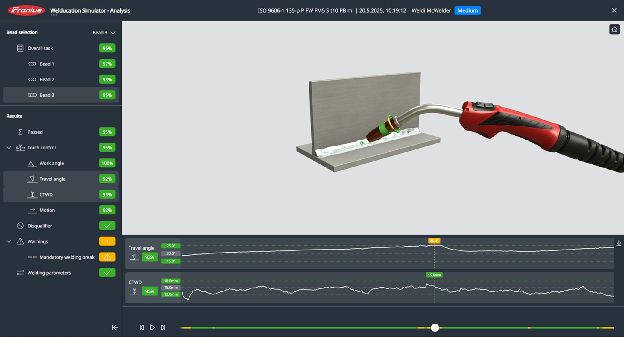
Individual symbols represent the individual elements of the welding movement (alignment, distance from workpiece and welding speed), and indicate the degree of accuracy:Note: The user remains connected for a certain period. After an extended period of inactivity, the Welducation Simulator is disconnected automatically.

Otherwise, the trainer has no way to assign the students to a course.

Otherwise, the trainer has no way to assign the students to a course.
"Course Template" is used as a template for courses. This allows continued use of existing course content, whereby only the new participants and the new course date are to be selected.
However, these two options also allow you to change the content as you wish.
Note: Once you have done this, a change is no longer possible.
If course templates are no longer required, they can be hidden for further course creation with "deprecated".
The theory content and theory jobs include PDF files for learning theory and revising for tests.
In addition to the theory content already prepared, it is possible to include your own theory content in the system.
Theory content can only be created in the "Theory" menu item and only in the form of PDF documents.
The status of the documents must be changed from "Draft" to "Published" to use them in the course.
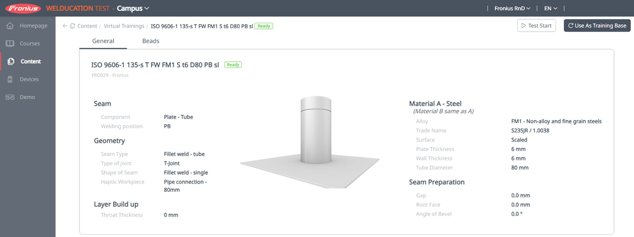
The virtual welding jobs are used to learn welding skills, such as:
When selecting virtual training, a detailed description of the respective weld seam profile is provided.
Virtual welding tasks can be edited, which allows you to modify virtual welding tasks individually. Two options are available:
Version 1:
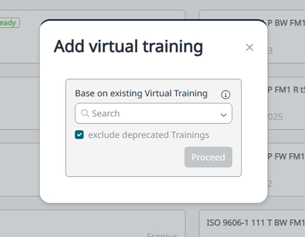
Version 2:
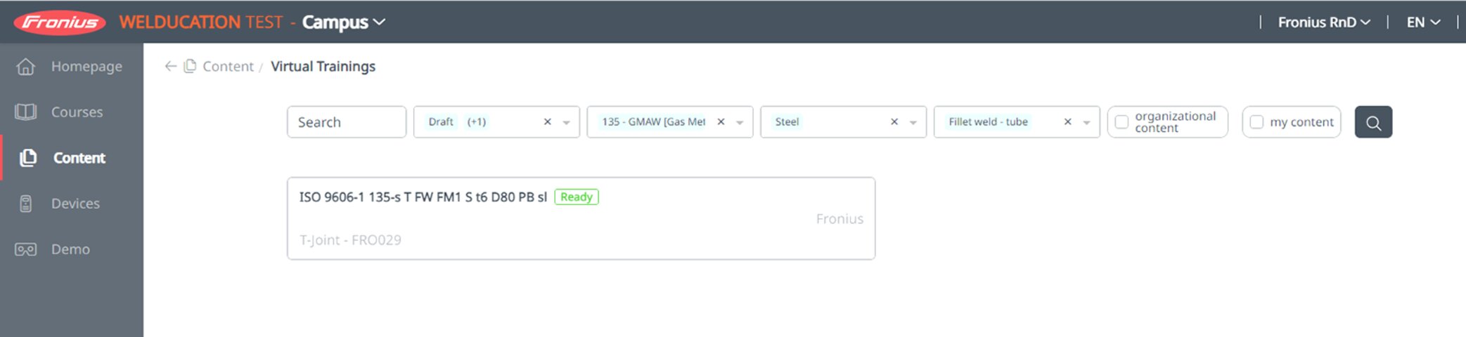
Further steps:
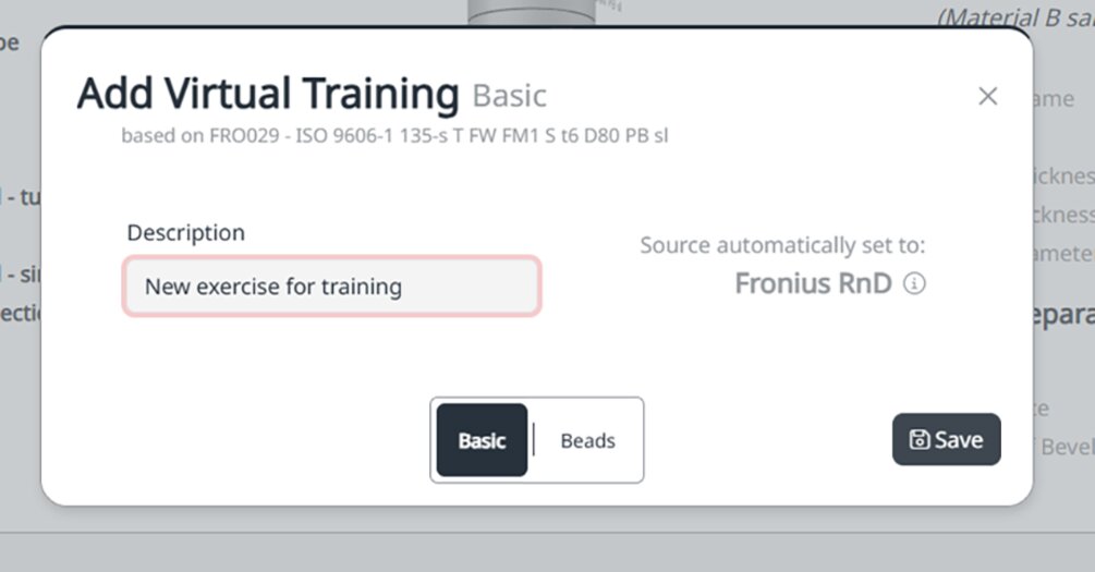
After confirming the virtual training, it is possible to select the level of difficulty.
"Easy":
"Medium":
"Hard":
You can then decide whether a knowledge check is created from scratch or based on an existing knowledge check.
Note: The sequence of questions and answers is random for the "Campus Student".
Note: Once you have done this, a change is no longer possible.
Initial calibration of the system is carried out at the factory prior to delivery. Calibration by the customer is not usually required.
However, subsequent calibration is possible if there is a deviation between the real and virtual objects (large offset).
During calibration, the individual components are compared with each other.
Note: The supplied calibration target is required.
Calibration is initiated by the trainer. Once the calibration has been initiated by the trainer, the calibration prompt only appears when a welding job is restarted.
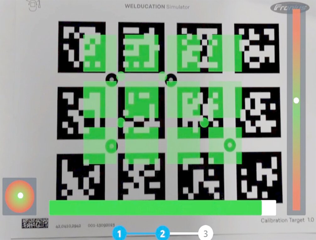
As soon as the superimposed overlay turns green, calibration starts automatically.
Once calibration is complete, the virtual welding task can be performed as usual.
Note: The "Load standard calibration" button should only be resorted to in extreme cases where there are very large deviations. For optimal calibration, always follow the procedure described above.
Initial calibration of the system is carried out at the factory prior to delivery. Calibration by the customer is not usually required.
However, subsequent calibration is possible if there is a deviation between the real and virtual objects (large offset).
During calibration, the individual components are compared with each other.
Note: The supplied calibration target is required.
Calibration is initiated by the trainer. Once the calibration has been initiated by the trainer, the calibration prompt only appears when a welding job is restarted.
As soon as the superimposed overlay turns green, calibration starts automatically.
Once calibration is complete, the virtual welding task can be performed as usual.
Note: The "Load standard calibration" button should only be resorted to in extreme cases where there are very large deviations. For optimal calibration, always follow the procedure described above.
Th "Demo" menu contains ready-made learning content and exercises for presentation or to get a quick overview of the course structure.
Th "Demo" menu contains ready-made learning content and exercises for presentation or to get a quick overview of the course structure.
To carry out a factory reset, the "Reset Device" action deletes all data in the system and resets the system to the factory settings.
Note: The administrator password is also reset. A factory reset can only be carried out by the administrator.
The factory reset is only supported in Standalone ("OFFLINE") operating mode.
"BackUp and Restore" stores all data, such as courses, participants, and results.
Note: "BackUp and Restore" is only available on the system on which it was created and can only be executed by the administrator and the trainer.
BackUp and Restore is only supported in Standalone ("OFFLINE") operating mode.
An integrated update function is available in software version 1.1 and higher.
The update files can be found in the DownloadCenter for the Welducation Simulator welding technology product in question.
Updates can only be carried out from one main version to the next: e.g., from version 1.1 to 1.2, then to 1.3. Interim versions or patches (e.g., 1.1.1 or 1.2.1) do not count as separate update levels.
Two options are available when carrying out updates, regardless of whether the Welducation Simulator is used in Standalone or Cloud operating mode.The Welducation Simulator restarts and performs the update.
The status LEDs indicate that an update is taking place. Once the update is complete, only the green status LED will light up.
The Welducation Simulator restarts and performs the update.
The status LEDs indicate that an update is taking place. Once the update is complete, only the green status LED will light up.
Note: If the update file is larger than 4 GB, the USB thumb drive must be formatted with NTFS. NTFS formatting is generally recommended for all USB thumb drives used for the update.
Wait a few minutes between restart attempts.
If the error occurs again despite several attempts and the steps listed above are unsuccessful, contact Fronius Support with a detailed error description.
Fronius Support requires the following data:
Wait a few minutes between restart attempts.
If the error occurs again despite several attempts and the steps listed above are unsuccessful, contact Fronius Support with a detailed error description.
Fronius Support requires the following data:
Wait a few minutes between restart attempts.
If the error occurs again despite several attempts and the steps listed above are unsuccessful, contact Fronius Support with a detailed error description.
Fronius Support requires the following data:
An electric shock can be fatal.
Before opening the device
Set the power switch to - O -.
Unplug the device from the grid.
Secure the device to prevent it from being switched back on again.
Use a suitable measuring instrument to ensure that electrically charged components (e.g., capacitors) are discharged.
Danger of electric shock due to inadequate ground conductor connection.
This can result in serious injury and damage to property.
The housing screws provide a suitable ground conductor connection for grounding the housing. Replacing the housing screws with other screws without a reliable ground conductor connection is prohibited.
Always use the original housing screws in the quantity initially supplied.
Observe the correct torque when tightening the housing screws.
| Cause: | The mains lead is disconnected, the mains plug is not plugged in. |
| Remedy: | Check the mains lead and insert the mains plug if necessary. |
| Cause: | The mains cable is not properly locked in place at the Welducation Simulator connection. |
| Remedy: | Make sure that the mains cable is properly locked in place at the Welducation Simulator connection. After inserting the mains cable, turn it 45° to the right until it audibly locks into place. |
| Cause: | The mains socket or mains plug is defective. |
| Remedy: | Replace the defective parts. |
| Cause: | The mains fuse has tripped. |
| Remedy: | Rectify the cause of the mains fuse tripping and restore the mains fuse. |
| Cause: | "PoE" ("Power over Ethernet") is set on the corresponding network distributor. |
| Remedy: | Deactivate "PoE". |
| Cause: | The network cable is disconnected, the network plug is not plugged in. |
| Remedy: | Plug in the network connector. |
| Cause: | The network socket or plug is defective. |
| Remedy: | Replace the defective parts. |
| Cause: | General network error. |
| Remedy: | Notify the network administrator. |
| Cause: | The welding torch or electrode holder is incorrectly calibrated. |
| Remedy: | Enable the calibration. Information on this can be found in section Calibration of the chapter "Welducation Campus software – Operation". |
| Cause: | Optical tracking not working. |
| Remedy: | Remove the cover on the optical camera in the XR headset for optical tracking. |
| Cause: | The tracking camera cable loose. |
| Remedy: | Check the micro-USB plug on the tracking camera. |
| Cause: | The welding torch / electrode holder is not connected. |
| Remedy: | Connect the welding torch / electrode holder. |
| Cause: | The welding torch / electrode holder cable or plug is defective. |
| Remedy: | Replace the welding torch / electrode holder cable or plug. |
| Cause: | The optical camera cable in the XR headset is defective. |
| Remedy: | Replace the optical camera cable. |
| Cause: | The tracking camera cable in the XR headset is defective. |
| Remedy: | Replace the tracking camera cable. |
| Cause: | The optical camera in the XR headset is defective. |
| Remedy: | Repair or replace the optical camera. If the optical camera is defective, contact Fronius Support. |
| Cause: | The tracking camera in the XR headset is defective. |
| Remedy: | Repair or replace the tracking camera. If the tracking camera is defective, contact Fronius Support. |
| Cause: | The XR headset is not connected to the Welducation Simulator. |
| Remedy: | Replace the XR headset connection cable. |
| Cause: | The XR headset is defective. |
| Remedy: | Repair or replace the XR headset. |
| Cause: | The welding torch is not connected. |
| Remedy: | Connect the welding torch. |
| Cause: | The welding torch cable or plug is defective. |
| Remedy: | Replace the welding torch cable or plug. |
| Cause: | Software error |
| Remedy: | If the error persists after restarting several times and (waiting for a few minutes between attempts), contact Fronius Support. |
| Cause: | Hardware error |
| Remedy: | Check all cables and connections. If the error persists after restarting several times and (waiting for a few minutes between attempts), contact Fronius Support. |
| Cause: | An unknown USB device has been plugged in during start-up (such as a USB thumb drive). |
| Remedy: | Remove the USB device or USB thumb drive. |
| Cause: | The "Standalone" operating mode is selected. |
| Remedy: | Use the welding torch to switch to the "Cloud" operating mode in accordance with section Changing operating mode. |
| Cause: | There is no suitable network connection. |
| Remedy: | In most cases, the network connection is not faulty, but the firewall or proxy settings must be adjusted. Check the criteria for a working network connection. Detailed information can be found in the section Cloud commissioning. |
| Cause: | There is a deviation from the actual time on the tablet. |
| Remedy: | Correct the time in the tablet settings or bring the tablet online at the time of synchronization. |
| Cause: | A software update may be available. |
| Remedy: | In the tablet settings under Software Update, search for possible updates and install them. |
| Cause: | Automatic translation is activated. |
| Remedy: | Disable automatic translation in the browser settings of the end device. |
| Cause: | An unknown error has occurred. |
| Remedy: | Even without an e-mail, the invitation can be retrieved after logging into the Welducation application. |
Danger from incorrect operation and work that is not carried out properly
This can result in severe personal injury and damage to property.
Only trained personnel are permitted to perform the work and functions described in this document, in accordance with the applicable national and international standards.
Read and understand this document.
Read and understand all the Operating Instructions for the system components, especially the safety rules.
Danger from electrical current
This may result in serious injuries or death.
Before starting work, switch off all the devices and components involved and disconnect them from the grid.
Secure all devices and components involved so they cannot be switched back on.
After opening the device, use a suitable measuring instrument to check that electrically charged components (such as capacitors) have been discharged.
Danger of electrical shock due to inadequate ground conductor connection
This can result in severe personal injury and damage to property.
The housing screws provide a suitable ground conductor connection for grounding the housing. Replacing the housing screws with other screws without a reliable protective conductor connection is prohibited.
Always use the original housing screws in the quantity initially supplied.
Observe the correct torque when tightening the housing screws.
Waste electrical and electronic equipment must be collected separately and recycled in an environmentally sound manner in accordance with the European Directive and national law. Used equipment must be returned to the distributor or through a local authorized collection and disposal system. Proper disposal of the used device promotes sustainable recycling of resources and prevents negative effects on health and the environment.
Packaging materialsMains voltage | 1~ 110 to 230 V AC |
Mains voltage tolerance | +/- 10% |
Mains frequency | 50 to 60 Hz |
Mains fuse | 16 A |
Current consumption (max.) | 2 A |
EMC emission class | B |
WLAN standards | 802.11b DSSS 802.11 g OFDM 802.11n OFDM 802.11a OFDM 802.11ac OFDM |
Mark of conformity | CE, FCC, FCC ID, IC |
Dimensions l x w x h | 560 x 215 x 370 mm |
Weight | 13 kg (28.66 lb.) |
Ambient air temperature range |
|
Relative humidity | up to 50% at +40 °C (+104 °F), |
For use at altitudes above sea level: | up to 2000 m (6500 ft.) |
Mains voltage | 1~ 110 to 230 V AC |
Mains voltage tolerance | +/- 10% |
Mains frequency | 50 to 60 Hz |
Mains fuse | 16 A |
Current consumption (max.) | 2 A |
EMC emission class | B |
WLAN standards | 802.11b DSSS 802.11 g OFDM 802.11n OFDM 802.11a OFDM 802.11ac OFDM |
Mark of conformity | CE, FCC, FCC ID, IC |
Dimensions l x w x h | 560 x 215 x 370 mm |
Weight | 13 kg (28.66 lb.) |
Ambient air temperature range |
|
Relative humidity | up to 50% at +40 °C (+104 °F), |
For use at altitudes above sea level: | up to 2000 m (6500 ft.) |
This radio transmitter (IC: 6158A-EQ261ACNIBT / Model: WPEQ-261ACNI(BT)) has been approved by ISED for operation with the antenna type used at the specified maximum allowable gain.
Mains voltage | Supply via Welducation Simulator |
EMC emission class | B |
Mark of conformity | CE, CSA |
Ambient air temperature range |
|
Relative humidity | up to 50% at +40 °C (+104 °F), |
For use at altitudes above sea level: | up to 2000 m (6500 ft.) |

Interactive HTML5 operating instructions are available on the Fronius website for Welducation Simulator and Welducation Campus:
Interactive HTML5 operating instructions are available on the Fronius website for Welducation Simulator and Welducation Campus: