General information
Important notes about this document
Purpose of the document
These Operating Instructions describe the operating principle, installation, and setup of a system running with the software solution "Fronius EMIL". The system is understood to mean several charging stations and Smart Meters that are controlled at a central location. Charging and energy management can be operated with a single system.
The document is intended exclusively for qualified personnel who are entrusted with the establishment and administration of the load management and charging management of an e-mobility infrastructure.
How information is presented in the document
The conventions regarding how information is presented in the document, which are set out below, have been defined in order to increase the readability and comprehensibility of the document. See the "Safety" chapter for the conventions on presenting safety-related information. The conventions described here refer to the way various types of information is presented, such as operational prerequisites, guidance, operator prompts, etc.
IMPORTANT! Indicates tips for correct operation and other particularly useful information. It does not indicate a harmful or dangerous situation.
Emphasis
- Display texts are written in bold, e.g., Settings.
- Sequences in the program are marked with an ">"e.g., Settings > System.
Overview
Funktionsbeschreibung
General
Fronius EMIL is a software solution for managing the load, charging, and energy of e-mobility infrastructure. With the help of Fronius EMIL, current loads can be controlled in such a way that cables and equipment are not overloaded and the available energy is intelligently managed. Compatible devices are controlled by Fronius EMIL via the open communication protocol OCPP for communication with charging stations, and via Message Queue Telemetry Transport (MQTT) for communication with one or more Smart Meters, and can therefore be coordinated with each other in the software. Compatible devices include electricity meters and charging stations (see Compatibility).
By intelligently managing compatible devices, load peaks can be avoided or the available energy distributed as needed. Fronius EMIL is available as a cloud solution. Different locations can be integrated into one system, while several systems can be created. Fronius EMIL supports any number of data points. A data point can be a charging point (charging solution) or an electricity meter (Smart Meter).
Fronius EMIL supports the regulated and prioritized charging (see Load management) of electric vehicles. Furthermore, PV-optimized charging is also supported (see Energy management).
System layout
The following schematic illustration shows the layout of a system for the e-mobility infrastructure of a large company. The system contains several company locations (Charge@work), home charging stations (Charge@home), and the central administration of Fronius EMIL. Further information on Charge@work and Charge@home can be found here: Introduction.
Target group
Fronius EMIL Partner
Fronius EMIL is aimed at all Fronius EMIL Partners. They are responsible for the configuration of Fronius EMIL with existing or new e-mobility hardware (e.g., charging stations, Smart Meters). They support the users of Fronius EMIL. A Fronius EMIL Partner introduces Fronius EMIL systems for companies, after which the facility managers of the companies are responsible for overseeing and supporting the systems.
To become a Fronius EMIL Partner, contact us via www.fronius.com.
Facility managers
Facility managers are responsible for a company's technical infrastructure. Facility managers plan, create, and edit various charging profiles, check power and current limits, manage and monitor charging and energy management.
IT administrators
A company's IT administrators are responsible for the implementation of Fronius EMIL within an existing company network.
Users and roles
- Partner
Is usually responsible for the installation of charging stations and other hardware at the end customer. Establishes systems in Fronius EMIL, creates new data points, and constructs the charging management of an infrastructure. Establishes load and energy management for the end customer. - Admin
Is responsible for managing and monitoring a system in Fronius EMIL. Creates and manages users and charging profiles.
All users of Fronius EMIL must be trained according to their user role. Suitable for this purpose are these Operating Instructions and any training provided by a Fronius EMIL Partner, for example.
| Partner | Admin |
|---|---|---|
Creating a new system | x | - |
Adding Smart Meters | x | - |
Adding charging points | x | - |
Starting/stopping a charging point | x | x |
Manually controlling charging points | x | x |
Charging point simulation | x | x |
Adding load management | x | - |
Editing load management | x | - |
Adding energy management | x | - |
Editing energy management | x | - |
Adding charging profiles | x | x |
Adding users | x | x |
Editing users | x | x |
Deleting users | x | x |
Enabling data point subscriptions | x | - |
Disabling data point subscriptions | x | - |
NOTE!
At least one admin user must exist in the system.
Deleting the last admin user or changing the role of the last admin user to another role is not permitted by the system.
Make sure at least one admin user is defined in the system.
Terms and conditions of use
Detailed terms of use are available directly at Fronius EMIL or at www.fronius.com .
Access to or use of the Fronius EMIL software signifies acceptance and compliance with these terms and conditions of use. If the terms and conditions of use are not agreeable then access to the Fronius EMIL software should not take place.
The terms and conditions of use set out the responsibilities of Fronius International GmbH towards the users of the Fronius EMIL software. In addition, the "dos" and "don'ts" are listed, which should be observed when using the Fronius EMIL software.
Data storage
All data resulting from the installation, operation or update of Fronius EMIL is stored on Fronius servers. Further information can be found in the Data Privacy Statement (available online at www.fronius.com or via Fronius EMIL).
Data Privacy Statement
The GDPR (General Data Protection Regulation) applies.
Security information
CAUTION!
Risk of unauthorized access to embedded devices due to lack of network security.
Access to the integrated devices (e.g., charging stations) may be unencrypted. Whether access is unencrypted depends on the respective device manufacturer. While setting up the system in a local network, there is a risk of unauthorized access, in particular if the network is not protected against unauthorized access. During operation, the data is encrypted via OCPP and MQTT.
Ensure that the network is protected by appropriate safeguards (e.g., VLAN, Mutual TLS).
Observe the security recommendations of the device manufacturer.
Ensure that the data is encrypted when the system is set up.
Compatibility
Introduction
The following section lists the components or devices that are compatible with Fronius EMIL. The information contained in this section comprises the device designation, the software version, and a comment regarding possible limitations. The limitations were identified during the tests carried out and always relate to the exact software versions listed.
Other software versions of the listed components may also be compatible with Fronius EMIL. If necessary, get in touch with your Fronius point of contact for further information.
The comments describe the limitations of a component identified during the tests in greater detail. A distinction is made between the Charge@work and Charge@home scenarios.
Charge@work
The charging station is located within the power grids, which are protected from overload by the load management of Fronius EMIL (e.g., company on-site parking).
Example: I charge my vehicle on the company site, all charging stations, charging profiles, energy consumption figures, and billing are managed by Fronius EMIL.
Charge@home
The charging station is located outside the power grids, which are protected from overload by the load management of Fronius EMIL (e.g., garage parking in a detached home).
Example: I have been provided with a charging station by my employer and use it to charge my vehicle at home. Billing takes place through the company, so the charging station is managed by Fronius EMIL.
Please note:
Compatibility with the devices of the third-party manufacturers listed below is only guaranteed for the device types and firmware versions expressly mentioned - deviations may result from individual technical conditions such as cabling, network structure, network access and interaction with other hardware. In the event of an automated firmware update and thus a newer version of the third-party devices, compatibility may no longer be guaranteed.
Smart Meter
IMPORTANT!
The specified software versions are supported. In order to avoid compatibility problems, the automatic software update of the device must be disabled.
Manufacturer | Model | Software version |
|---|---|---|
Fronius International GmbH | Smart Meter
| 2.4.0-0042 |
TQ-Systems GmbH | Energy Manager
| 3.1.4 |
Charging stations
IMPORTANT!
The specified software versions are supported. In order to avoid compatibility problems, the automatic software update of the device must be disabled.
AC charging solution
Manufacturer | Model | Software version | Downgrade possible* | Remark |
|---|---|---|---|---|
Fronius International GmbH | Wattpilot
| 40.7 | No | Charge@work
|
Schrack Technik GmbH | i-CHARGE CION Pro 22kW | 5.32.0-18730 | - | |
eCharge Hardy Barth GmbH |
| 2.0.2 | Yes | Charge@home
|
KEBA Energy Automation GmbH | KeContact
| 1.15.x | No | Charge@home
|
*With some manufacturers, it is possible to switch to an earlier software version (perform a downgrade). |
DC charging solution
Manufacturer | Model | Software version | Downgrade possible | Remark |
|---|---|---|---|---|
alpitronic GmbH | hypercharger
| hyc_v1.6.7 | - | - |
User interface
Overview
User interface
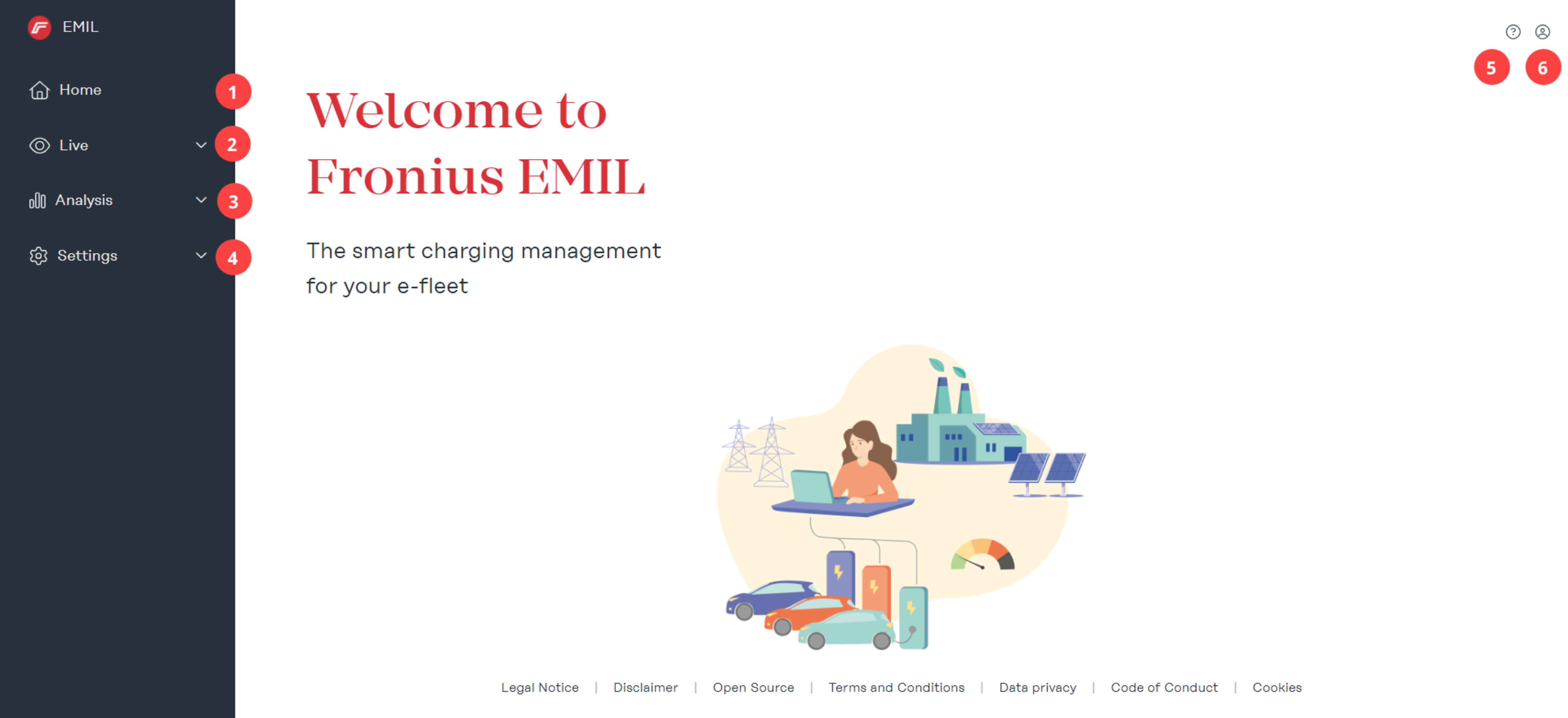
| (1) | Start page |
| (2) | Live In the "Data Points" submenu, the entire system is displayed in list form. The created system is graphically displayed in the "System overview" submenu. |
| (3) | Analysis The "Charging sessions" submenu lists all planned, running, and completed charging processes. In addition, a CSV or XLSX file can be exported for a defined period of time. All messages from the system, as well as the data points created in it, are listed in the "Event log" submenu. |
| (4) | Settings New users are added and existing users can be edited in the "Users" submenu. A role must be assigned to each user. Several charging profiles and RFID cards can be assigned to each user. Automatic messages for system events can be configured in the "Messages" submenu. Possible system events include: Charging started, charging error, charging finished. For example, by sending a message, a user may be notified when charging has finished and the charging station may be released for the next user. New charging profiles can be added and existing charging profiles can be managed in the "Charging profiles" submenu. Charging profiles are used for load and/or energy management and are assigned to users. New elements can be added to a system in the "System" submenu. The following elements are available: Group, Smart Meter, Charging Point, Load Manager, and Energy Manager. |
| (5) | Support Solutions for possible problems are listed on the "Support" page. |
| (6) | Profile On the "Profile" page, the user has access to their account and to the system selection. In addition, the system name of the selected system is displayed. |
Overview
User interface
| (1) | Start page |
| (2) | Live In the "Data Points" submenu, the entire system is displayed in list form. The created system is graphically displayed in the "System overview" submenu. |
| (3) | Analysis The "Charging sessions" submenu lists all planned, running, and completed charging processes. In addition, a CSV or XLSX file can be exported for a defined period of time. All messages from the system, as well as the data points created in it, are listed in the "Event log" submenu. |
| (4) | Settings New users are added and existing users can be edited in the "Users" submenu. A role must be assigned to each user. Several charging profiles and RFID cards can be assigned to each user. Automatic messages for system events can be configured in the "Messages" submenu. Possible system events include: Charging started, charging error, charging finished. For example, by sending a message, a user may be notified when charging has finished and the charging station may be released for the next user. New charging profiles can be added and existing charging profiles can be managed in the "Charging profiles" submenu. Charging profiles are used for load and/or energy management and are assigned to users. New elements can be added to a system in the "System" submenu. The following elements are available: Group, Smart Meter, Charging Point, Load Manager, and Energy Manager. |
| (5) | Support Solutions for possible problems are listed on the "Support" page. |
| (6) | Profile On the "Profile" page, the user has access to their account and to the system selection. In addition, the system name of the selected system is displayed. |
Installation
Requirements
System requirements
Fronius EMIL is a browser-based software for which we recommend the following minimum requirements.
Hardware requirements- PC, mouse, keyboard
- min. 1 440 x 1 080 pixels
- Google Chrome
- Microsoft Edge
- All data points to be integrated into the system must have a stable network connection.
- Enable 443 (HTTPS), 8883 (MQTT) for the network on which the data points are located, e.g., if the charging stations on a network are located in a parking lot, the specified ports on this network must be enabled:
- mqtt.space.fronius.com:8883
- ocpp.space.fronius.com:443
System installation
Creating a new system
Ordering and installation of Fronius EMIL is carried out by a Fronius EMIL Partner. The Fronius EMIL Partner creates a system, the necessary data points, and load and energy management for an end customer (admin role).
To create the first system, perform the following steps:
1Launch your Internet browser (seeSystem requirements)
2Go to the page emil.fronius.com .
3Log in or register.
4Click on + new system to create a system.
To create additional systems, perform the following steps:
1Go to the page emil.fronius.com the last system selected will automatically appear.
2Click on Profile > System selection at the top right.
3Click on + new system to create a system.
Access to the system
As a Fronius EMIL Partner, perform the following steps to grant administrator access to a system:
1Admin: Launch your Internet browser (seeSystem requirements).
2Admin: Go to the page emil.fronius.com .
3Admin: Log in with your credentials or create an account.
4Admin: Copy the displayed account ID and send it to your Fronius EMIL Partner.
5Partner: Click on "Settings" > "Users" > "Add account".
6Partner: Enter the account ID in the input field and set the admin role for the administrator.
7Admin: Access to the system is now available. Additional users can be added directly by the administrator.
The new system will then be set up by the Fronius EMIL Partner. This creates new data points, groups the data points in consultation with the administrator, and adds load managers and energy managers to the system.
For further information about setting up the new system, see Setting up the system.
Installing third-party devices
Please note:
The following information regarding the commissioning of third-party devices from the named third-party manufacturers (such as KEBA, Schrack and the like) is intended solely as general, non-binding information and can therefore not be used as a substitute for professional advice or information.
Although this information has been carefully prepared, it does not claim to be factually correct, complete and/or up to date. In particular, this information cannot take into account the particular circumstances of each individual case.
Reference is therefore made below to the third-party Operating Instructions for a specific type of third-party device and a specific firmware version valid at the time of publication of these Operating Instructions - an update to newer third-party device types or references to the third-party Operating Instructions is therefore not provided and it is solely your responsibility to independently obtain and observe the applicable third-party Operating Instructions when commissioning the third-party devices as well as any information on newer third-party devices or firmware versions.
Any liability on the part of Fronius International GmbH is excluded. The respective third-party manufacturer should be contacted for specific concerns.
Connecting Smart Meters
Adding Smart Meters
To add a Smart Meter, the corresponding permissions must be available (see Users and roles).
Adding Smart Meters
1Click on "Settings" > "System" > "Add element" > "+ Smart Meter"
2 Implement the necessary settings in the pop-up menu. Mandatory fields are marked with a *.
- Name
For a good system overview, it is advisable to assign a descriptive name. For example, the equipment identification, or a combination with a location abbreviation, e.g., ATTHA Main (AT = Austria, THA = Thalheim, Main = feed point). - Assignment
Assign the Smart Meter to a parent group. The top group is your system. - Driver
If it is a physically installed charging station, the driver "smartmeter-agent-v1: vx.x.x" must be selected. For a simulated Smart Meter, you need the driver "smartmeter-simulator-v1:vx.x.x". - Settings
Under the "Settings" tab, set the following parameters:- "Max. amperage [A]" = physical limit of the Smart Meter
- "Monitored amperage [A]" = control value; if this value is exceeded, warnings are displayed in the system
- "Rated voltage [V]" = depending on the country (Austria: 230 V)
- "Rated frequency [Hz]" = depending on the country (Austria: 50 Hz
3Click "Save".
4Open the added Smart Meter again. Click "Edit" (pencil icon).
5Go to "Settings" and scroll to "Smart Meter overview".
6Make a note of the username, password, and path. You must enter this information in the user interface of the Smart Meter in order to establish a connection.
Adding Smart Meters
To add a Smart Meter, the corresponding permissions must be available (see Users and roles).
Adding Smart Meters
1Click on "Settings" > "System" > "Add element" > "+ Smart Meter"
2 Implement the necessary settings in the pop-up menu. Mandatory fields are marked with a *.
- Name
For a good system overview, it is advisable to assign a descriptive name. For example, the equipment identification, or a combination with a location abbreviation, e.g., ATTHA Main (AT = Austria, THA = Thalheim, Main = feed point). - Assignment
Assign the Smart Meter to a parent group. The top group is your system. - Driver
If it is a physically installed charging station, the driver "smartmeter-agent-v1: vx.x.x" must be selected. For a simulated Smart Meter, you need the driver "smartmeter-simulator-v1:vx.x.x". - Settings
Under the "Settings" tab, set the following parameters:- "Max. amperage [A]" = physical limit of the Smart Meter
- "Monitored amperage [A]" = control value; if this value is exceeded, warnings are displayed in the system
- "Rated voltage [V]" = depending on the country (Austria: 230 V)
- "Rated frequency [Hz]" = depending on the country (Austria: 50 Hz
3Click "Save".
4Open the added Smart Meter again. Click "Edit" (pencil icon).
5Go to "Settings" and scroll to "Smart Meter overview".
6Make a note of the username, password, and path. You must enter this information in the user interface of the Smart Meter in order to establish a connection.
Fronius Smart Meter IP
The compatible devices are available at Compatibility .
For information and help with the initial installation of the Smart Meter, please visit the manufacturer's website at Fronius Smart Meter IP.
Requirements- The Smart Meter is installed
- A connection to the Internet has been established
- Port 8883 for outgoing connections is enabled in the firewall
- Fronius EMIL: The Smart Meter is created
- Fronius EMIL: Username, password, and path are known
- Connect the Smart Meter to the Internet via Ethernet Cable
- Smart Meter has a static IP address
Connecting Smart Meters
1Connect to the Smart Meter via the Smart Meter access point. See Operating Instructions for Fronius Smart Meter IP.
2Go to the user interface of the Smart Meter; to do so, enter the IP address 192.168.250.181 into a browser.
3Enter the password "123".
4Click on "Advanced Settings" > "Network".
5Click on "LAN (Network Cable)" and then on "Next".
6Click on "Automatic IP address over DHCP" and then on "Next".
7Click on "Save and apply"
8Disconnect from the access point. The Smart Meter is now accessible on the network with the assigned IP address. It is advisable to configure a static IP address.
9Implement the settings below on the user interface of the Smart Meter.
10Click "Advanced Settings" > "Reboot device" to restart the Smart Meter.
Implement the following settings on the user interface of the Smart Meter
Parameter | Setting |
|---|---|
Server configuration |
|
Server name | mqtt.space.fronius.com |
Port | 8883 |
Username | Enter the generated username of the device from EMIL (retrieve via "Settings" > "System" > Smart Meter "Edit" > "Settings" > "Smart Meter overview") |
Password | Enter the generated password of the device from EMIL (retrieve via "Settings" > "System" > Smart Meter "Edit" > "Settings" > "Smart Meter overview") |
MQTT security | TLS certificates |
MQTT topic prefix | Enter the path from EMIL (retrieve via "Settings" > "System" > Smart Meter "Edit" > "Settings" > "Smart Meter overview") |
Configure MQTT topics | Remote configuration (recommended) |
Firmware updates via MQTT | Enable (recommended) |
Client ID | Enter the generated username of the device from EMIL (retrieve via "Settings" > "System" > Smart Meter "Edit" > "Settings" > "Smart Meter overview") |
TQ Energy Manager EM420
The compatible devices are available at Compatibility .
For information and help with the initial installation of the Smart Meter, please visit the manufacturer's website at TQ Energy Manager EM420.
Requirements- The Smart Meter is installed
- A connection to the Internet has been established
- Port 8883 for outgoing connections is enabled in the firewall
- Fronius EMIL: The Smart Meter is created
- Fronius EMIL: Username, password, and path are known
- Connect the Smart Meter to the Internet via Ethernet Cable
- Smart Meter has a static IP address
Connecting Smart Meters
1Go to the user interface of the Smart Meter; See Operating Instructions for TQ Energy Manager EM420.
2Implement the settings below on the user interface of the Smart Meter.
3Click "Device settings" > "Device" > "Restart" to restart the Smart Meter.
Implement the following settings on the user interface of the Smart Meter
Parameter | Setting |
|---|---|
Device settings > Network settings |
|
Time zone | UTC |
MQTT interface > Server configuration |
|
Server name | mqtt.space.fronius.com |
Port | 8883 |
Username | Enter the generated username of the device from EMIL (retrieve via "Settings" > "System" > Smart Meter "Edit" > "Settings" > "Smart Meter overview") |
Password | Enter the generated password of the device from EMIL (retrieve via "Settings" > "System" > Smart Meter "Edit" > "Settings" > "Smart Meter overview") |
Client ID | Enter the generated username of the device from EMIL (retrieve via "Settings" > "System" > Smart Meter "Edit" > "Settings" > "Smart Meter overview") |
Certificates | Accept |
MQTT topics |
|
Data format | Simple list of measured values |
Transmission interval | 1 second |
MQTT topics > Smart Meter |
|
Activate MQTT topics | Activate |
MQTT topic for the measured data | Enter the path from EMIL (retrieve via "Settings" > "System" > Smart Meter "Edit" > "Settings" > "Smart Meter overview") |
Keep last value notification in the message broker | No |
MQTT value range quality | 0 |
Connecting a charging station
Adding charging points
A charging point in Fronius EMIL corresponds to a charging station in reality. To add a charging point, the corresponding permissions must be available (see Users and roles).
Adding charging points
1Click on "Settings" > "System" > "Add element" > "+ charging point"
2Implement the necessary settings in the pop-up menu. Mandatory fields are marked with a *.
- Name
For a good system overview, it is advisable to assign a descriptive name. For example, the equipment identification, or a combination with a location abbreviation, e.g., attha‑01 (at = Austria, tha = Thalheim, 01 = charging station number). - Assignment
Assign the charging point to a parent group. The top group is your system. - Driver
If it is a physically installed charging station, the driver "ocpp16-cp-agent-v1:vx.x.x" must be selected. For a simulated charging station, you need the driver "chargepoint-electrical-simulator-v1:vx.x.x". - Connection
Under the tab "Connection", all connections (plugs) of the charging station are configured to correspond to the physical connections of the real charging station. After configuring a connection, click on "Add."
3Click "Save".
4Open the added charging point again. Click "Edit" (pencil icon).
5Switch to "Connection" and scroll to "Overview of charging points and connection".
6Make a note of the username, password, and path. You must enter this information in the user interface of the charging station in order to establish a connection.
Adding charging points
A charging point in Fronius EMIL corresponds to a charging station in reality. To add a charging point, the corresponding permissions must be available (see Users and roles).
Adding charging points
1Click on "Settings" > "System" > "Add element" > "+ charging point"
2Implement the necessary settings in the pop-up menu. Mandatory fields are marked with a *.
- Name
For a good system overview, it is advisable to assign a descriptive name. For example, the equipment identification, or a combination with a location abbreviation, e.g., attha‑01 (at = Austria, tha = Thalheim, 01 = charging station number). - Assignment
Assign the charging point to a parent group. The top group is your system. - Driver
If it is a physically installed charging station, the driver "ocpp16-cp-agent-v1:vx.x.x" must be selected. For a simulated charging station, you need the driver "chargepoint-electrical-simulator-v1:vx.x.x". - Connection
Under the tab "Connection", all connections (plugs) of the charging station are configured to correspond to the physical connections of the real charging station. After configuring a connection, click on "Add."
3Click "Save".
4Open the added charging point again. Click "Edit" (pencil icon).
5Switch to "Connection" and scroll to "Overview of charging points and connection".
6Make a note of the username, password, and path. You must enter this information in the user interface of the charging station in order to establish a connection.
Fronius Wattpilot
The compatible devices are available at Compatibility .
For information and help with the initial installation of the charging station, please visit the manufacturer's website at Fronius Wattpilot.
Requirements- The charging station is installed
- A connection to the Internet has been established
- Port 443 for outgoing connections is enabled in the firewall
- The Fronius Solar.wattpilot app is installed
- Fronius EMIL: The charging point is created
- Fronius EMIL: Username, password, and path are known (see also Setting up the system)
- The charging station has a stable WLAN connection
Connecting a charging station
1Open the Fronius Solar.wattpilot app on your device.
2Go to "Internet" > "OCPP".
3Implement the following settings and click "Save":
Parameter | Setting |
|---|---|
Access control |
|
Authentication | Authentication required |
Cable unlock | Locked when car is connected |
Lock current level selection | Locked when car is connected |
OCPP |
|
OCPP 1.6J | Activate |
OCPP server address | wss://<Username>:<Password>@ocpp.space.fronius.com/<Path> |
Status | Connected |
Custom certificate | Deactivated |
KEBA
The compatible devices are available at Compatibility .
For information and help with the initial installation of the charging station, please visit the manufacturer's website at KEBA SUPPORT.
Requirements- The charging station is installed
- A connection to the Internet has been established
- Port 443 for outgoing connections is enabled in the firewall
- EMIL: The charging point is created
- EMIL: Username, password, and path are known (see also Setting up the system)
- The charging station is connected to the Internet with an Ethernet cable
- The charging station has a static IP address
Connecting a charging station
1Go to the user interface of the charging station. See Operating Instructions for KEBA charging station.
2Navigate to: "Configuration" > "OCPP"
3Implement the following settings:
Parameter | Setting |
|---|---|
Device |
|
Authorization | ON |
Online authorization mode | FirstOnline |
Browser time | Determine browser time |
Rated voltage | 230 |
Network connection |
|
Local DHCP server | OFF |
OCPP |
|
Charge point identity | Enter the generated username of the device from EMIL (retrieve via "Settings" > "System" > Charging point "Edit" > "Connection" > "Overview of charging points and connection") |
OCPP communication protocol | OCPP 1.6 JSON |
OCPP backend address | ocpp.space.fronius.com |
OCPP backend port | 443 |
OCPP backend path | ocpp16 |
Secure OCPP backend connection | ON |
OCPP backend authentication procedure | BasicAuthentication |
Authorization key | Enter the generated password of the device from EMIL (retrieve via "Settings" > "System" > Charging point "Edit" > "Connection" > "Overview of charging points and connection") |
Reconnection interval | 30 |
WebSocket ping interval | 50 |
Predefined token | Leave empty |
Interval of the transmission of meter readings during the charging process | 3 |
Time-based interval for transmitting meter readings. | 0 |
External TCP meter |
|
TCP house connection monitoring | OFF |
NOTE!
Note the correct DIP switch settings of the charging station. Information on this can be found on the manufacturer's website, under KEBA Service & support.
Schrack
The compatible devices are available at Compatibility .
For information and help with the initial installation of the charging station, please visit the manufacturer's website at Schrack e-mobility.
Requirements- The charging station is installed
- A connection to the Internet has been established
- EMIL: The charging point is created
- EMIL: Username, password, and path are known (see also Setting up the system)
- Connect the charging station to the Internet via Ethernet Cable
- The charging station has a static IP address
Connecting a charging station
1Go to the user interface of the charging station. Further information on this can be found on the manufacturer's website, under www.schrack.at.
2Go to "Backend " > "OCPP".
3Implement the following settings and restart the charging station after saving:
Parameter | Setting |
|---|---|
Network - LAN | |
Display network settings | Display |
Ethernet configuration mode | Automatic (DHCP client) |
DHCP client request reattempts | 10 |
DHCP client request timeout duration | 10 |
Interval between two DHCP request reattempts | 10 |
Client hostname | Schrack-Lan |
Backend - connection |
|
Connection type | Ethernet |
Backend > OCPP |
|
OCPP ChargeBoxIdentity (ChargePointID) | Enter the generated username of the device from EMIL (retrieve via "Settings" > "System" > Charging point "Edit" > "Connection" > "Overview of charging points and connection") |
Identity of the charging device | - |
OCPP mode | OCPP-J 1.6 |
WebSockets JSON OCPP URL of the backend | wss://ocpp.space.fronius.com/ocpp16 |
Websockets proxy | - |
WebSockets keep alive interval | 50 |
Strictness of the OCPP connection | Secure ciphers only |
Password for HTTP basic authentication | Enter the generated password of the device from EMIL (retrieve via "Settings" > "System" > Charging point "Edit" > "Connection" > "Overview of charging points and connection") |
Always send heartbeat messages | On |
Send informative StatusNotifications | On |
Send StatusNotifications for errors | On |
Send USB errors via StatusNotifications | Off |
StatusNotification state transition strategy | Occupied during charging |
Allow long access to configuration keys | Off |
Numerical values for Boolean configuration keys | On |
Prevent charging in the event of an ongoing backend malfunction | Off |
Status "not available" at the start of the firmware update | On |
Force status "available/not available" of OCPP connector | Available |
Backend > Other |
|
Backend connection timeout duration | 60 |
Number of attempts to transmit transaction-relevant messages | 3 |
Number of attempts to transmit transaction-relevant calibration messages | 0 |
SSL mode as client | Normal SSL authentication |
TCP watchdog timeout | 10 800 |
Show backend connection failure as error | On |
Backend > Utility meter |
|
Data transfer for tariff and overall use | Off |
Meter values sampled data (OCPP) | Energy.Active.Import.Register, Power.Active.Import, Current.Offered, Current.Import |
Meter value sample interval (OCPP) | 1 |
Meter values aligned data (OCPP) | Energy.Active.Import.Register |
Time-coordinated data transmission interval [s] (OCPP) | 0 |
Re-transmit meter value messages | On |
Current flow direction of L1 of the primary meter | Suppress sign |
Current flow direction of L2 of the primary meter | Suppress sign |
Current flow direction of L3 of the primary meter | Suppress sign |
Current flow direction of L1 of the secondary meter | Suppress sign |
Current flow direction of L2 of the secondary meter | Suppress sign |
Current flow direction of L3 of the secondary meter | Suppress sign |
Backend gateway for banner parking sensors |
|
Send parking space occupancy data to the backend | Off |
Backend notification by e-mail |
|
E-mail notification of errors | Off |
Backend - HawkBit client |
|
HawkBit client | Off |
|
|
Authorization - Free charging |
|
Charging is free | Off |
RFID tag for free charging with full OCPP and fixed RFID modes | Freecharging |
When in doubt, allow charging | Off |
Authorization - Overview |
|
Send OCPP authorization for remote start | On |
Mode when stopping a transaction | Normal |
Authorization - RFID settings |
|
Activate RFID | On |
RFID mode | RFID only |
Uppercase/lowercase sensitive for RFID tag | Uppercase |
Authorization - RFID whitelists |
|
Activate local whitelist | Off |
Activate OCPP whitelist | Off |
Local pre-authorization | Off |
Local offline authorization | Off |
Authorization - HLC 15118 |
|
15118 configuration | Off |
Strictness of the 15118 connection | Standard |
Autocharge | Off |
|
|
System - Overview |
|
Time zone | UTC |
REST interface | Deactivated |
Restore time | Only when the software is restarted |
Tcpdump interface | Ethernet |
eCharge Hardy Barth
The compatible devices are available at Compatibility .
For information and help with the initial installation of the charging station, please visit the manufacturer's website at eCharge Hardy Barth.
Requirements- The charging station is installed
- A connection to the Internet has been established
- Port 443 for outgoing connections is enabled in the firewall
- EMIL: The charging point is created
- EMIL: Username, password, and path are known (see also Adding charging points)
- Connect the charging station to the Internet via Ethernet Cable
- The charging station has a static IP address
Connecting a charging station
1Go to the user interface of the charging station. Further information on this can be found on the manufacturer's website, under eCharge Hardy Barth.
2Go to "Configuration".
3Implement the following settings, save and restart the charging station:
Parameter | Setting |
|---|---|
Global options | |
Charging station type | Cable/socket |
Time zone | Set |
Auth. mode | OCPP |
Key switch type | None (recommended) |
Min./max. current | 6 - 32 A (recommended) |
External control | Deactivated |
OCPP options |
|
OCPP | Activated |
Uri/CPID | Double-click next to CPID to open the menu |
Uri/CPID - | Enter path from EMIL (retrieve via "Settings" > "System" > Charging point "Edit" > "Connection" > "Overview of charging points and connection"): wss://ocpp.space.fronius.com/<path> |
Uri/CPID - username | Enter the generated username of the device from EMIL (retrieve via "Settings" > "System" > Charging point "Edit" > "Connection" > "Overview of charging points and connection") |
Uri/CPID - password | Enter the generated password of the device from EMIL (retrieve via "Settings" > "System" > Charging point "Edit" > "Connection" > "Overview of charging points and connection") |
Verify CERT | Activate |
Mains options |
|
Overcurrent/Eco | Deactivate (recommended) |
Peak shave | - (recommended) |
ECO reference | - (recommended) |
Network options |
|
DHCP | Activate |
alpitronic hypercharger
The compatible devices are available at Compatibility .
For information and help with the initial installation of the charging station, please visit the manufacturer's website at alpitronic hypercharger.
Requirements- The charging station is installed
- A connection to the Internet has been established
- Port 443 for outgoing connections is enabled in the firewall
- EMIL: The charging point is created
- EMIL: Username, password, and path are known (see also Adding charging points)
- Connect the charging station to the Internet via Ethernet Cable
- The charging station has a static IP address
Ladestation verbinden
1Go to the user interface of the charging station. Further information on this can be found on the manufacturer's website, under alpitronic hypercharger.
2Implement the following settings, save and restart the charging station:
Parameter | Setting |
|---|---|
General > System Settings | |
Time zone | Do not set |
Network > Preferred network | |
To change default | Wired Connection |
OCPP > OCPP File |
|
ConnectorPhaseRotation | Adjust according to physical phases |
OCPP > Boot.INI File |
|
chargePointIdentity |
|
URI/CPID - | Enter path from EMIL (retrieve via "Settings" > "System" > Charging point "Edit" > "Connection" > "Overview of charging points and connection"): wss://ocpp.space.fronius.com/<Pfad> |
URI/CPID - username | Enter the generated username of the device from EMIL (retrieve via "Settings" > "System" > Charging point "Edit" > "Connection" > "Overview of charging points and connection") |
URI/CPID - password | Enter the generated password of the device from EMIL (retrieve via "Settings" > "System" > Charging point "Edit" > "Connection" > "Overview of charging points and connection") |
Verify CERT | Activate |
Mains options |
|
Overcurrent/Eco | Deactivate (recommended) |
Peak shave | - (recommended) |
ECO reference | - (recommended) |
Network options |
|
DHCP | Activate |
System
General
Charging profile
A charging profile contains limit values for charging processes. These profiles can be assigned to users for specific groups in a system, or to an entire system. The user (charging-authorized user) can charge within the limit values defined in the charging profile.
With a charging profile, charging-authorized users can be assigned various load and energy management settings. Each charging-authorized user (for creating a charging-authorized user, see Users ) can be assigned one or more charging profiles and RFID cards, e.g. for charging at different company locations or at different charging stations.
Load management
Load management in Fronius EMIL is used to protect your infrastructure. This prevents load peaks. Load peaks can occur at times of the day when the demand for electricity is highest and the infrastructure is insufficiently designed for this.
The settings implemented apply to each charging profile and to all users (charging-authorized users) to whom the charging profile is assigned.
Avoiding load peaks
The following illustration shows how load peaks can be avoided by using load management at certain times of the day. We assume the basic consumption of an infrastructure (building load / building consumption) between 6 am and 5 pm. From 6 am, the energy demand of the infrastructure increases because employees want to charge their e-vehicles.

Settings
In the load management of the charging profile, you can set the minimum and maximum permissible amperage as well as the energy that a charging-authorized user is permitted to use when charging. The priority can be set (1 = highest priority), whereby vehicles with a low priority are charged later with little available energy.
The minimum amperage [A] is the minimum current with which a user may charge a vehicle, if the infrastructure permits it. If the infrastructure does not permit it and the value falls below this limit, charging does not take place. It is recommended to set 6 A as the minimum value, as most vehicles require this amperage as the minimum charging current.
The maximum amperage [A] is the maximum current with which a user may charge a vehicle, provided that the technical conditions allow this.
The maximum energy [kWh] is the total energy with which a user may charge a vehicle, provided that the technical conditions allow this. More energy may not be drawn.
Possible charging interruptions can be prevented by activating Allow charging pause. Some vehicles do not resume the charging process after an interruption.
Energy management
Energy management in Fronius EMIL is used to optimize your energy use. The settings implemented apply to each charging profile and to all users to whom the charging profile is assigned. When creating a charging profile, different energy management settings can be defined for different days of the week.
In the energy management of the charging profile, you can set the minimum and maximum permissible energy as well as the maximum power that a charging-authorized user is permitted to use when charging. A priority can also be set (1 is the highest priority), which allows mutual priorities to be set in the profiles when adding several energy management settings (it may be the case that several settings cannot be fulfilled in parallel, so it is important to set the priority).
Optimization > Yes, optimized self-consumption can be set, in order to preferably use self-generated energy for charging the electric vehicle fleet.
The max. energy [kWh] is the total energy that a user is authorized to use when charging. More energy may not be drawn.
The minimum energy [kWh] is the minimum energy that a user is authorized to use when charging, even if the optimization is set to Yes, optimized self-consumption. If no self-generated energy is available, charging is still carried out up to this value. After that, up to max. energy [kWh], if self-generated energy is available.
In the case of Finished until, setting a time can be used to define that the min. energy [kWh] will be used for charging by this set time. It is irrelevant, whether self-generated energy is actually available when optimization is activated.
Possible charging interruptions can be prevented by activating Allow charging pause. Some vehicles do not resume the charging process after an interruption.
The charging timer allows the user to define the entire energy management for the period of one calendar week. Click on "Add" to save different settings for different days. For example, the optimization can be set to active from 6 am to 5 pm from Monday to Friday, whereby the optimization does not take effect outside this period.
Simulation
Both Smart Meters and charging points can be simulated. This is helpful for testing purposes.
To enable simulation, the driver "chargepoint-electrical-simulator" ("Settings" > "System") must be defined for the created data points. Simulated Smart Meters have no further function. For simulated charging points, the connection and disconnection of a vehicle can be simulated.
Settings
Setting up the system
The Fronius EMIL Partner sets up the new system for the administrators.
Creating a new system
1Click on "Settings" > "System".
2Click "Add element" > "+ Smart Meter" to add the first Smart Meter.
3Implement the necessary settings for a newly added Smart Meter.
4Repeat steps 2 and 3 if necessary.
5Click "+ charging point" to add a charging station.
6Implement the necessary settings for a newly added charging station.
7Repeat steps 5 and 6 if necessary.
8Click "+ Load Manager".
9Implement the necessary settings for a newly added Load Manager.
Use the Load Manager to arrange the created data points (Smart Meters, charging points) in a hierarchy. The hierarchy created should correspond to the reality of your infrastructure; if necessary, the structure can be freely selected. The data points are displayed in the "System overview" as they are set up in the Load Manager. See Load management.
Creating an Energy Manager takes place in the same way as creating the Load Manager. However, the hierarchy is not important here. The data points should be added to an Energy Manager where this makes sense. See Energy management.
Group
Creating a group can be used to organize and structure a system. It makes sense to group the system based on the locations of the data points created.
Creating a group
1Click on "Settings" > "System" > "Add element" > "+ group"
2Follow the instructions
Smart Meter
See Adding Smart Meters.
Charging point
Load Manager
The Load Manager is required to protect the infrastructure. In the Load Manager, you map the physical structure of your system. This structure is visible under "Live" > "System overview".
Set up Load Manager, see Setting up the system.
Energy Manager
The Energy Manager is required for optimization of the self-consumption.
Set up Energy Manager, see Setting up the system.
Charging profiles
Creating charging profiles
1Click on "Settings" > "Charging profiles" > "Add"
2Follow the instructions
Users
Creating users
A user with the "User" role does not have direct access to the system. This user must be created in order to be assigned a charging profile and an RFID card.
Creating charging-authorized users
1Click on "Settings" > "User" > "Create user"
2Follow the instructions
NOTE!
To add a charging profile and an RFID card to the newly created user, you must "Edit" the newly created user and add a charging profile and RFID card after saving it for the first time.
Delete User
If all authorizations are withdrawn from a user, the user remains in the system and is visible to the administrator, but can no longer interact with the system. All loading sessions and personal data are retained and the administrator can grant the user authorizations for the system again at any time.
The delete button removes the user from the system. All authorizations and personal data are deleted. It is no longer possible to restore the user. The loading data remains in the system in anonymized form.
Troubleshooting
Causes and solutions
Possible errors when using Fronius EMIL can have many causes due to the complexity of a system, which are not directly triggered by Fronius EMIL.
Ensure that the following infrastructure is functional:- Network
- Charging station
- Smart Meter
Causes and solutions
Possible errors when using Fronius EMIL can have many causes due to the complexity of a system, which are not directly triggered by Fronius EMIL.
Ensure that the following infrastructure is functional:- Network
- Charging station
- Smart Meter
Support
For end users, your installer or the Fronius EMIL Partner is the first point of contact for support with troubleshooting.
In addition to training, Fronius International GmbH offers Fronius EMIL Partner support to assist with the installation, commissioning, and configuration of the software. Support is the point of contact for Fronius EMIL Partners if faults and errors that occur in Fronius EMIL cannot be remedied independently.
Appendix
General
Software update
Regular updates are carried out to improve functionality and fix errors.
The software functions affected by an update will be published in the Release Notes.
Release Notes
The Release Notes provide an overview of the changes, enhancements, and any other amendments to the software. The Release Notes are listed in Release Notes.
Release Notes
Overview of releases
In this section you will find detailed information on the latest versions of our software. We describe the new features, improvements and bug fixes for each release.
Please note that this guide will be updated regularly to include the latest release information. If you have any questions or require further assistance, please do not hesitate to contact your contact person.
Fronius EMIL 10
The following software functions are affected by the Fronius EMIL 10 release. (Stand: 02. 07. 2024)
Dashboard
The most important system data (system status, charging points, smart meters) are visualized on the EMIL homepage and provide a quick overview.
Design adjustments
Improved user-friendliness and design. All dialogs now open in full-screen mode, which increases clarity and orientation.
Endless scrolling
Automatic reloading of table entries when scrolling. The content of all lists is automatically reloaded, eliminating the need to scroll through pages in lists.
Group selection
A central selection option has been integrated for quick access to individual locations or other groups. This is available throughout the system.
Fronius EMIL 9
The following software functions are affected by the Fronius EMIL 9 release. (As of: 10. 06. 2024)
Various preparations for future releases.
Fronius EMIL 8
The following software functions are affected by the Fronius EMIL 8 release. (As of: 01. 05. 2024)
Endless scrolling
Automatic reloading of table entries when scrolling. The content of lists is automatically reloaded, so that there is no need to scroll through the pages in lists.
Event Log
Improved performance and access speed.
Delete User
Users can now be deactivated by withdrawing all role authorizations to access the system without deleting the user and billing data from the system. Reactivation is possible by the administrator.
For further information see Users .
Fronius EMIL 7
The following software functions are affected by the Fronius EMIL 7 release. (As of: 03. 04. 2024)
API
API gateway functionality has been technically enhanced.
Bug fixes
Various bug fixes.
Fronius EMIL 6
The following software functions are affected by the Fronius EMIL 6 release. (As of: 06. 03. 2024)
Responsive design
Improvements in responsive design.

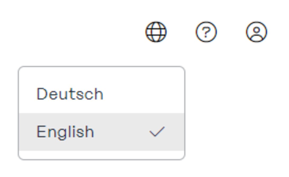
Change language
The user interface can be displayed in English or German.
Compatibility
The "Alpitronic Hypercharger DC" DC charging station is compatible.
Fronius EMIL 5
The following software functions are affected by the Fronius EMIL 5 release. (As of: 08. 02. 2024)
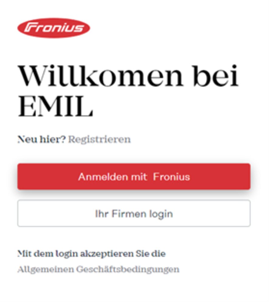
Login
Logging in to the system is possible with your company name as defined in Fronius EMIL. The company login can be set by the system administrator and adjusted if necessary.
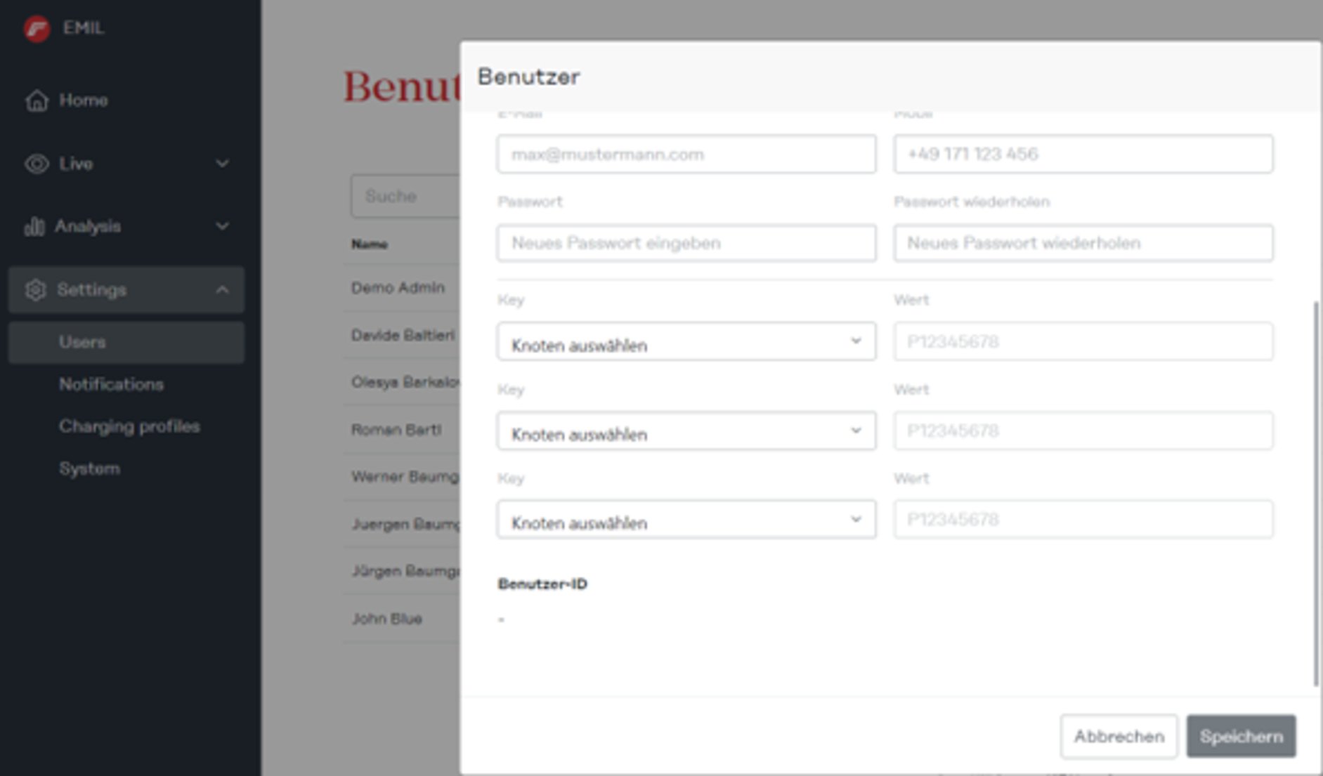
User entry fields
Additional entry fields are available when creating a new local user (charging-authorized user). It is possible for up to three further items of information to be added, for example the personnel number, license plate number or chassis number. For billing, the data is also output in an additional column when exporting charging sessions (as CSV or XLSX).